Cooking up circuits for future projects
Serves: One ambitious electronics chef
Total Time: Several hours of schematic design, datasheet reading, routing mistakes, and quiet contemplation
This week marked my first real step into designing a custom PCB that I could carry forward into future weeks and eventually my final project. Rather than designing something disposable, I wanted a board that was versatile, expandable, and wearable-project friendly.
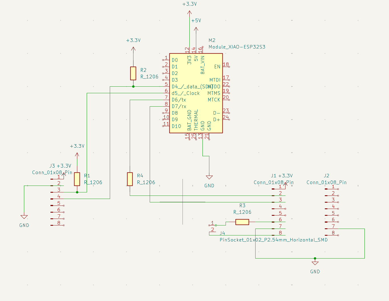
At the heart of the board is the Xiao ESP32-S3. I chose this microcontroller very intentionally. The ESP32-S3 is extremely versatile: it supports WiFi and Bluetooth, has strong processing power for real-time sensor analysis, and—crucially for my long-term plans—has excellent support for battery-powered operation. Even though I did not immediately use WiFi in this week, I wanted the option to pursue networking or web-based interfaces later without redesigning the entire board.
For motion sensing, I selected the MPU6050, a classic 6-DOF accelerometer and gyroscope. This part is extremely well documented, widely used, and has known libraries that integrate smoothly with the ESP32. Since my eventual goal was to compute steps per minute with reasonable accuracy, I needed a sensor that could reliably capture periodic acceleration patterns over time. The MPU6050 was ideal for this use case and struck a good balance between accuracy, complexity, and learning curve.
To handle audio output, I added a DFPlayer Mini. This module allows audio playback directly from a microSD card, completely offloading audio decoding from the microcontroller. This was important because it meant the ESP32 could focus on sensor processing and control logic rather than timing-sensitive audio tasks. I also added a simple 2-pin speaker output so that I could plug in a small speaker without additional amplification circuitry.
While studying the datasheets—particularly for the MPU6050—I added two pull-up resistors to the design. These pull-ups are connected to the I²C communication lines (SDA and SCL).
I²C is an open-drain (or open-collector) communication protocol, meaning that devices on the bus can only actively pull the signal line low. They cannot drive the line high. Without pull-up resistors, the lines would float when no device is pulling them low, resulting in undefined logic levels, unreliable communication, and unpredictable behavior.
The pull-up resistors ensure that when no device is actively transmitting a low signal, the SDA and SCL lines are pulled to a known high voltage level. This creates clean, well-defined digital transitions that the ESP32 and MPU6050 can reliably interpret. In short: without pull-ups, I²C simply does not work correctly.
While some development boards include internal pull-ups, relying on them can be risky—especially in custom PCB designs where trace length, noise, and bus capacitance matter. By explicitly adding external pull-up resistors, I ensured stable communication and avoided hard-to-debug intermittent sensor failures later on.
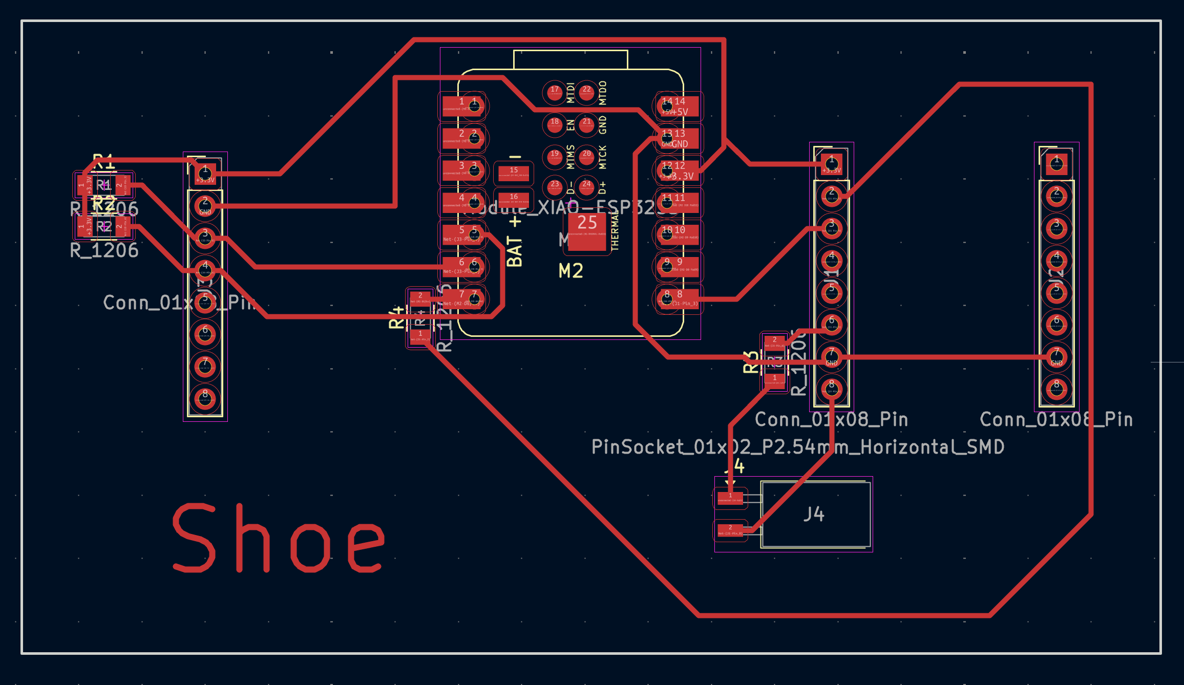
To complete the schematic, I added several 0-ohm resistors. These act as configurable jumpers, allowing signals to cross or reroute cleanly without overlapping traces. They also give me flexibility if I later need to isolate or reconfigure parts of the circuit without redesigning the entire board.
At this point, the design followed the documentation closely: power regulation, decoupling capacitors, clean ground routing, and clear signal paths. Once everything was connected and electrically sound, the PCB design felt complete and ready to move into fabrication in the following weeks.
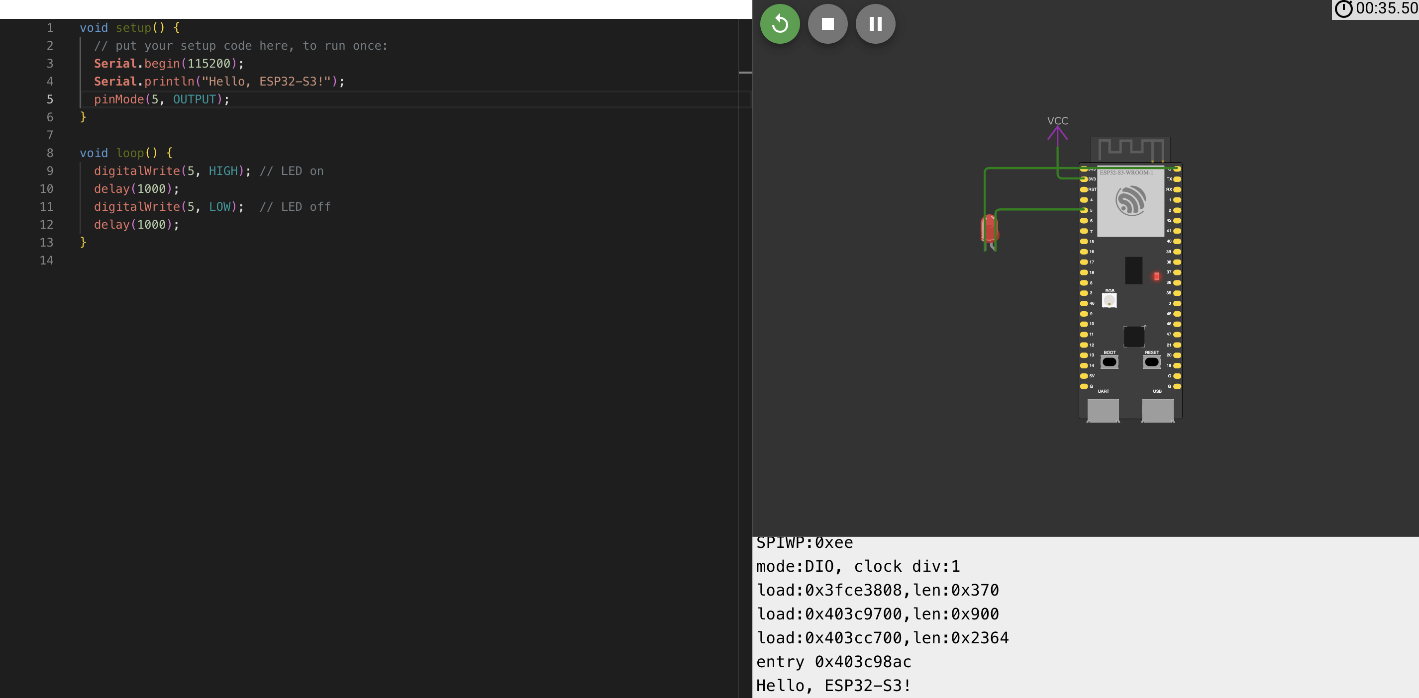
Because simulating the full PCB would not provide meaningful insight, I instead created a small demonstration simulation to satisfy the assignment requirements. I used Wowki to build a simple LED blink circuit, allowing me to verify basic timing logic and microcontroller behavior in a controlled environment.
This week taught me that good PCB design is less about connecting parts randomly and more about understanding why each component exists. Every resistor, module, and trace serves a purpose. Designing this board with future projects in mind gave me a strong foundation that paid off repeatedly in later weeks—especially when things inevitably broke.