Final Project Spirobs
My motivation is to think about objects that are camouflaged but have a very interesting and surprising functional form. I originally thought about making a legged robot, but I decided I wanted to explore a different mechanical form rather than rigid legs which I do have prior knowledge in. I have always been curious about alternatives, such as tendon based robots. This led me to explore the following videos / research.
Note! This website is written chronologically as I have updates, so the initial plan of replicating Spirobs and having it curl in more axes was pivoted into a plant robot that still uses the same Spirobs mechanism but with a different intention.
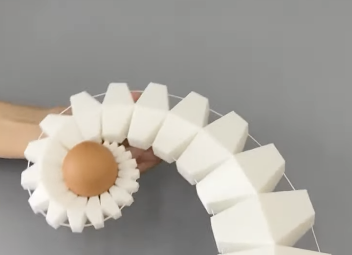
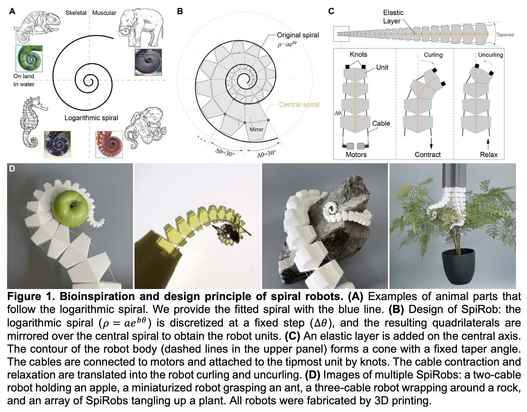
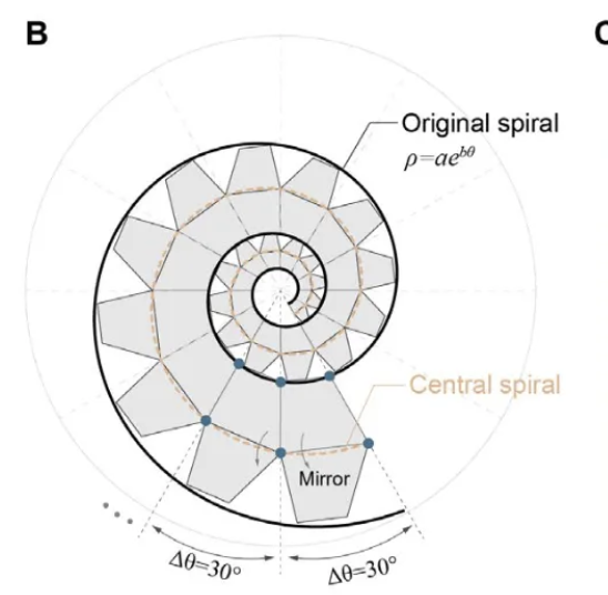
I really liked the elegant design of the SpiRobs paper, https://arxiv.org/abs/2303.09861
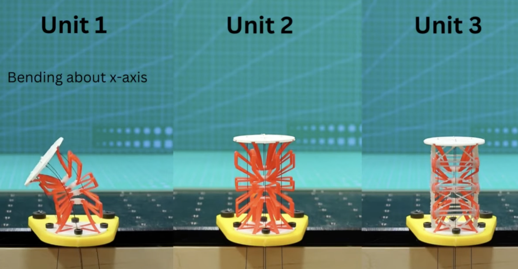
Potential extensions I want to explore is how to add more DOF to it by having small solenoids on some of the segments that can clamp down on the wire. This video describes this idea https://www.youtube.com/watch?v=y9G-J1wP5O4&t=136s
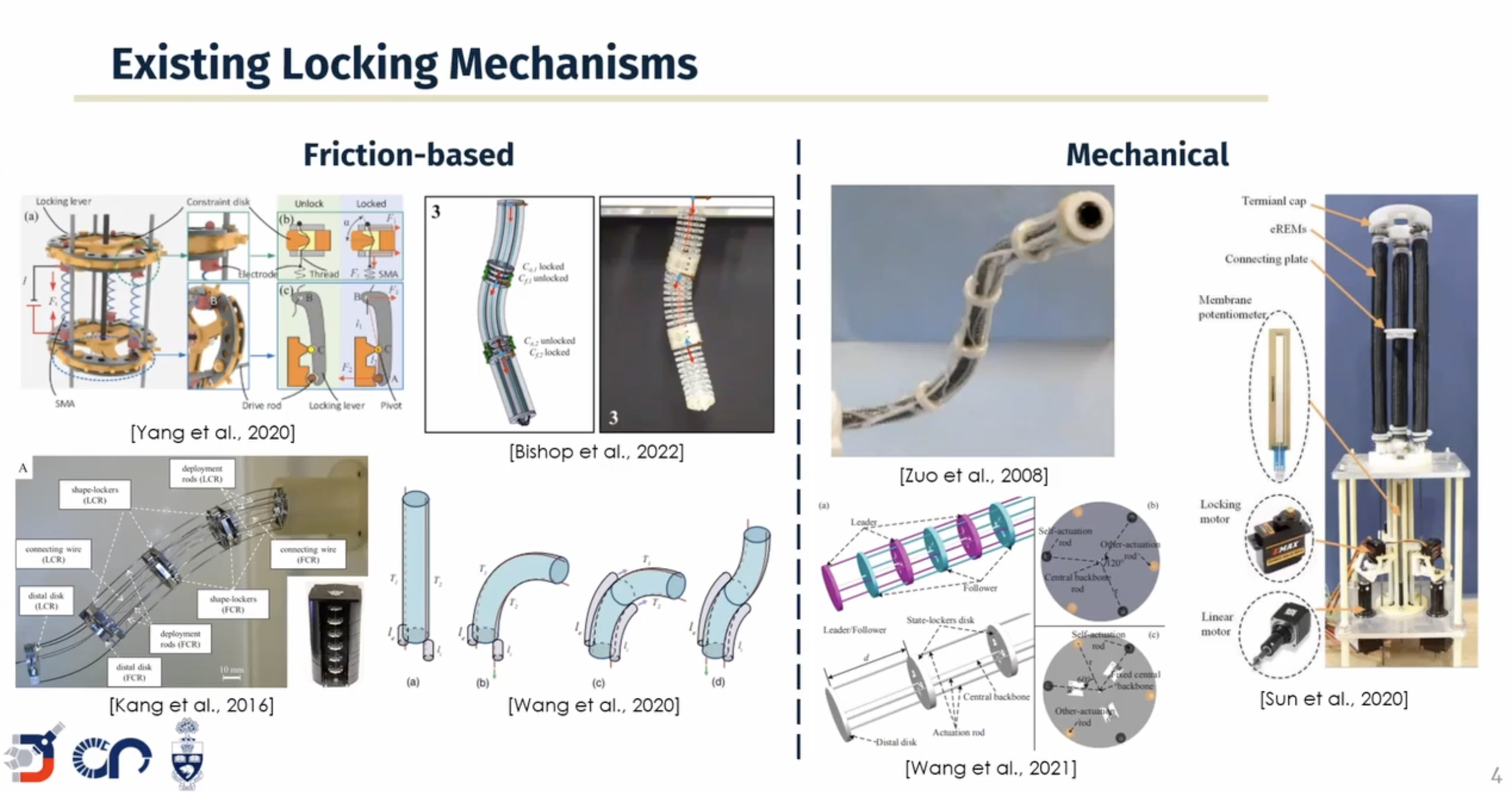
Following spiral development I will first recreate SpiRobs, and if time permits, try to develop a locking mechanism to extend the DoF of SpiRobs.
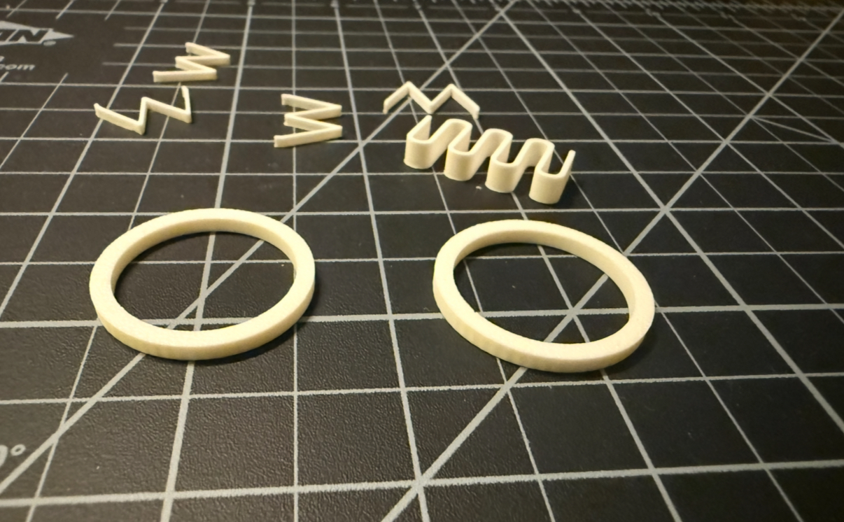
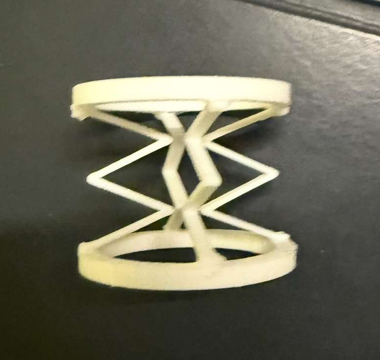
I made some early attempts at understanding how to build a flexible core - this is 3d printed via PLA and it was too stiff and brittle. I ordered TPU filament as a result.
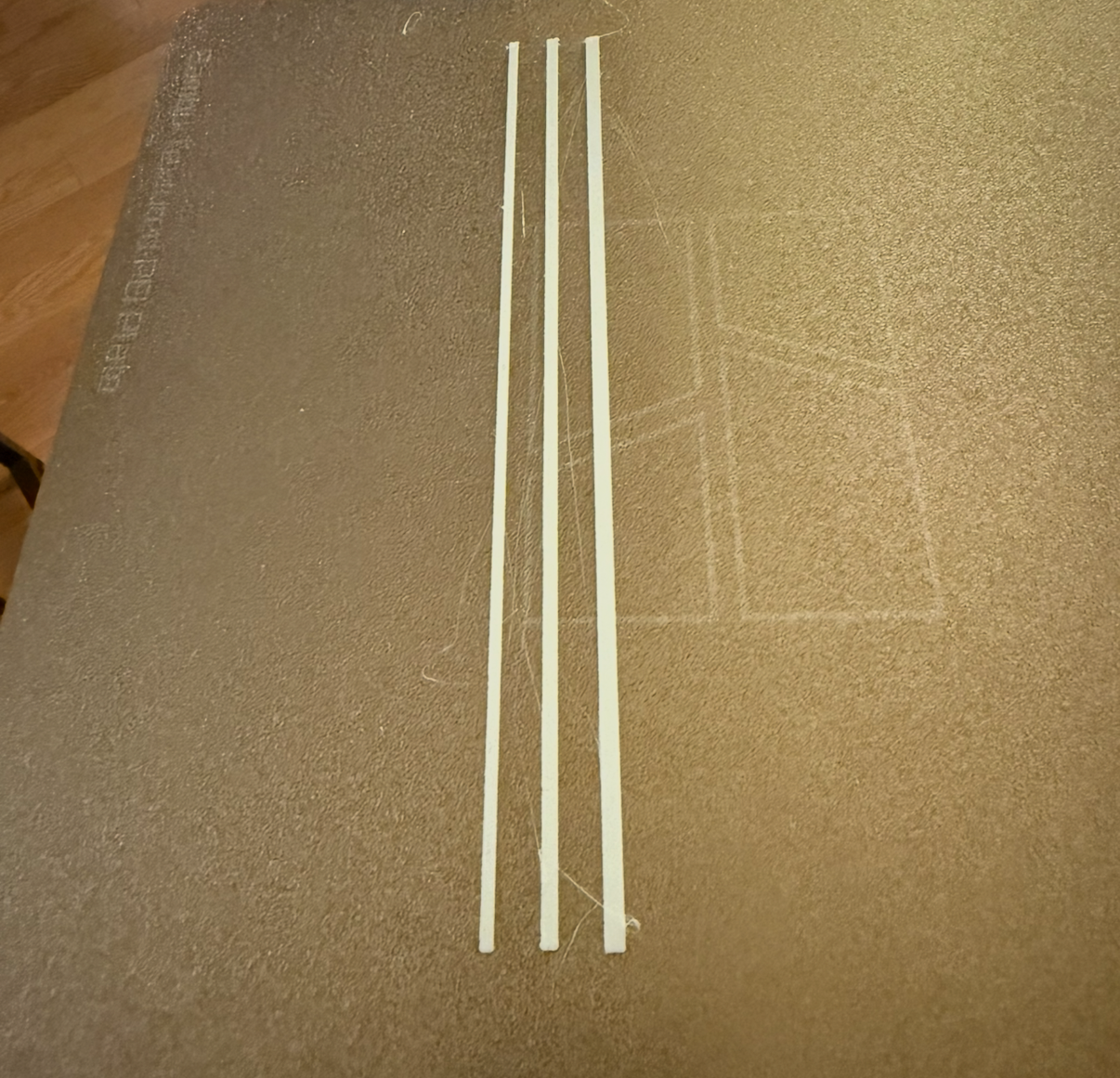
The TPU arrived and I first printed a long core of different thickness, but then I made the height just 1mm and it was too floppy. Then settled on a long rod with a 3mm x 3mm square base as the core. Then I went to designing the cad files of each segment.
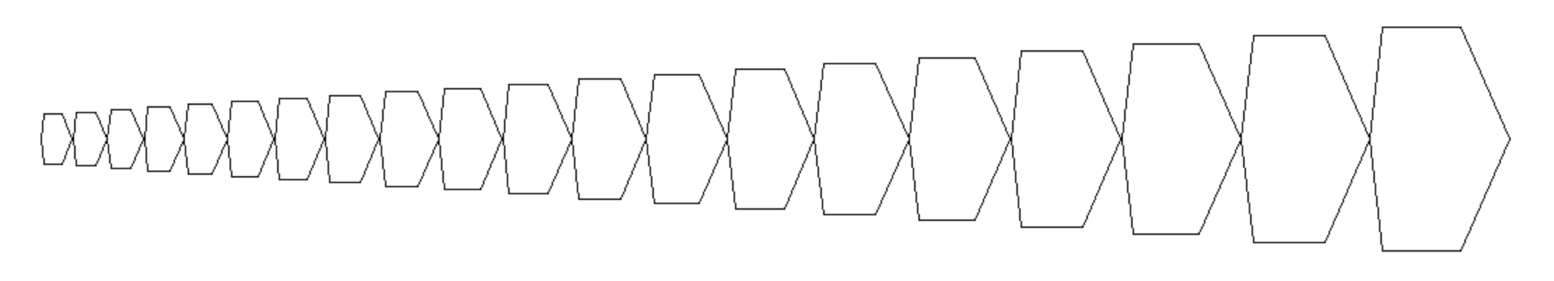
I wanted to write a python program to find the vertex of each segment. I coded the basic logic first myself and then worked with ChatGPT to finish the code. Originally I was trying to have python save an STL file - but that didn’t work well and after chatting with Anthony he suggested I used SVG / DXF, and that worked perfectly. So the code below generates a DXF of each segment - there is still an unfixed bug which I will point out later.
# made in collaboration with ChatGPT
import math
import numpy as np

# coef for p = a e^{bθ}
a = 0.05
b = 0.2

def p(a, b, theta):
    return a * math.exp(theta * b)

def polar_to_cartesian(p, theta):
    x = p * math.cos(theta)
    y = p * math.sin(theta)
    return x, y

def reflect_points_across_line(points_to_reflect, line_points):
    (x1, y1), (x2, y2) = points_to_reflect
    (x3, y3), (x4, y4) = line_points

    P1, P2 = np.array([x1, y1]), np.array([x2, y2])
    A, B = np.array([x3, y3]), np.array([x4, y4])

    d = B - A
    d = d / np.linalg.norm(d)

    def reflect_point(P):
        AP = P - A
        proj = A + np.dot(AP, d) * d
        return 2 * proj - P

    return tuple(reflect_point(P1)), tuple(reflect_point(P2))

def get_segment(a, b, d, i, p):
    theta_1 = d * i
    theta_2 = d * (i + 1)

    # Radii
    p1 = p(a, b, theta_1)
    p2 = p(a, b, theta_2)
    p3 = (p(a, b, theta_1 + 2 * math.pi) - p1) / 2 + p1
    p4 = (p(a, b, theta_2 + 2 * math.pi) - p2) / 2 + p2

    # Convert to Cartesian
    x1, y1 = polar_to_cartesian(p1, theta_1)
    x2, y2 = polar_to_cartesian(p2, theta_2)
    x3, y3 = polar_to_cartesian(p3, theta_1)
    x4, y4 = polar_to_cartesian(p4, theta_2)

    # Reflect across line connecting (x3, y3) and (x4, y4)
    (x5, y5), (x6, y6) = reflect_points_across_line(
        [(x1, y1), (x2, y2)], [(x3, y3), (x4, y4)]
    )

    # --- Reorient segment so that (x3, y3) -> (0,0) and (x4, y4) -> (L,0) ---
    # Translation
    points = np.array([
        [x1, y1],
        [x2, y2],
        [x3, y3],
        [x4, y4],
        [x5, y5],
        [x6, y6],
    ])
    translated = points - np.array([x3, y3])

    # Rotation
    vec = np.array([x4 - x3, y4 - y3])
    angle = -math.atan2(vec[1], vec[0])  # rotate so line aligns with +x axis
    rot = np.array([
        [math.cos(angle), -math.sin(angle)],
        [math.sin(angle),  math.cos(angle)],
    ])
    rotated = translated @ rot.T

    # Unpack rotated points
    x1, y1, x2, y2, x3, y3, x4, y4, x5, y5, x6, y6 = rotated.flatten()

    # Build polygon (closing loop)
    polygon = [
        (float(x1), float(y1)),
        (float(x2), float(y2)),
        (float(x4), float(y4)),
        (float(x6), float(y6)),
        (float(x5), float(y5)),
        (float(x3), float(y3)),
        (float(x1), float(y1)),
    ]
    return polygon

for i in range(10):

    points = get_segment(a, b, math.pi / 6, i, p)

    import ezdxf
    from pathlib import Path

    def points_to_dxf(points, filename="points.dxf", closed=False, scale=100):
        """
        Converts a list of (x, y) points into a DXF file containing a polyline.
        scale: multiply coordinates (so small float coords become visible in CAD)
        """
        doc = ezdxf.new(dxfversion="R2010")
        msp = doc.modelspace()

        # scale and optionally close
        pts = [(x * scale, y * scale) for x, y in points]
        if closed and pts[0] != pts[-1]:
            pts.append(pts[0])

        # Add the polyline
        msp.add_lwpolyline(pts, close=closed)

        # Save
        doc.saveas(filename)
        print(f"✅ Saved {filename}")

    points_to_dxf(points, filename=f"parts/segment_{i}.dxf", closed=True)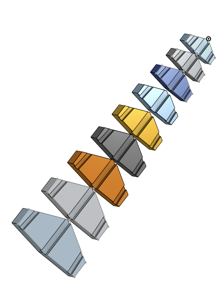
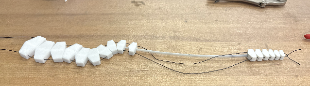
I then printed 2 copies of it which will be sandwiched together, and then added the fishing line.
Here I manually added each part in OnShape, and moved it. I need to figure out how to automate this process. I then extruded some holes for the TPU core and the cable wire (I am using fishing line).
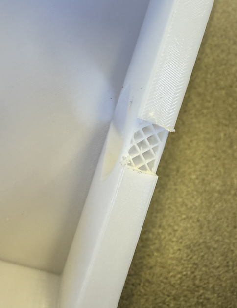
Next todo - the segments weren’t aligning and I initially suspected a math bug, but later realized I had assembled them backwards. Then I noticed where the fishing line meets the glued segments, there is a lot of stress there and it snaps through the super glue - so I need to redesign it with that in mind.
Midterm Review
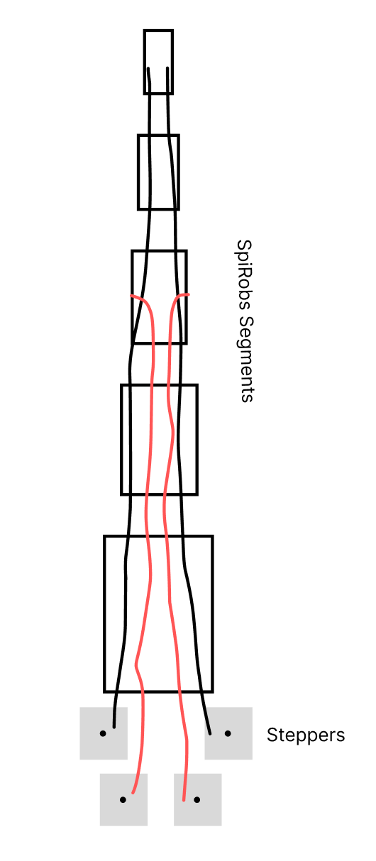
The black lines are the main cables to pull the segments, the red are for clamping the black cables. There will be 4 stepper motors.
The tasks left to do are,
Fix the segment generator bug
Make a larger version (around a foot in total length)
Make another motor driver
design and add the cable clamping mechanism
Timeline:
this week fix the generator bug and make a larger final size version and design the clamping mechanism
Next week is make the second motor driver
Then assemble a casing for all the steppers in the third week
// This is modified from the class code by Neil
// hello.DRV8428-D11C.ino
//
// DRV8428-D11C stepper hello-world
//
// Neil Gershenfeld 5/30/21
//
// This work may be reproduced, modified, distributed,
// performed, and displayed for any purpose, but must
// acknowledge this project. Copyright is retained and
// must be preserved. The work is provided as is; no
// warranty is provided, and users accept all liability.
//
#define DIR_1 D0
#define STEP_1 D1
#define DIR_2 D2
#define STEP_2 D3
#define DELAYHIGH 10
#define DELAYLOW 500
void setup() {
digitalWrite(STEP_1,LOW);
digitalWrite(STEP_2,LOW);
pinMode(STEP_1,OUTPUT);
pinMode(STEP_2,OUTPUT);
digitalWrite(DIR_1,LOW);
digitalWrite(DIR_2,LOW);
pinMode(DIR_1,OUTPUT);
pinMode(DIR_2,OUTPUT);
}
void loop() {
digitalWrite(STEP_1,HIGH);
digitalWrite(STEP_2,HIGH);
delayMicroseconds(DELAYHIGH);
digitalWrite(STEP_1,LOW);
digitalWrite(STEP_2,LOW);
delayMicroseconds(DELAYLOW);
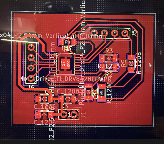
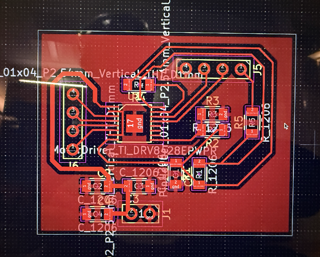
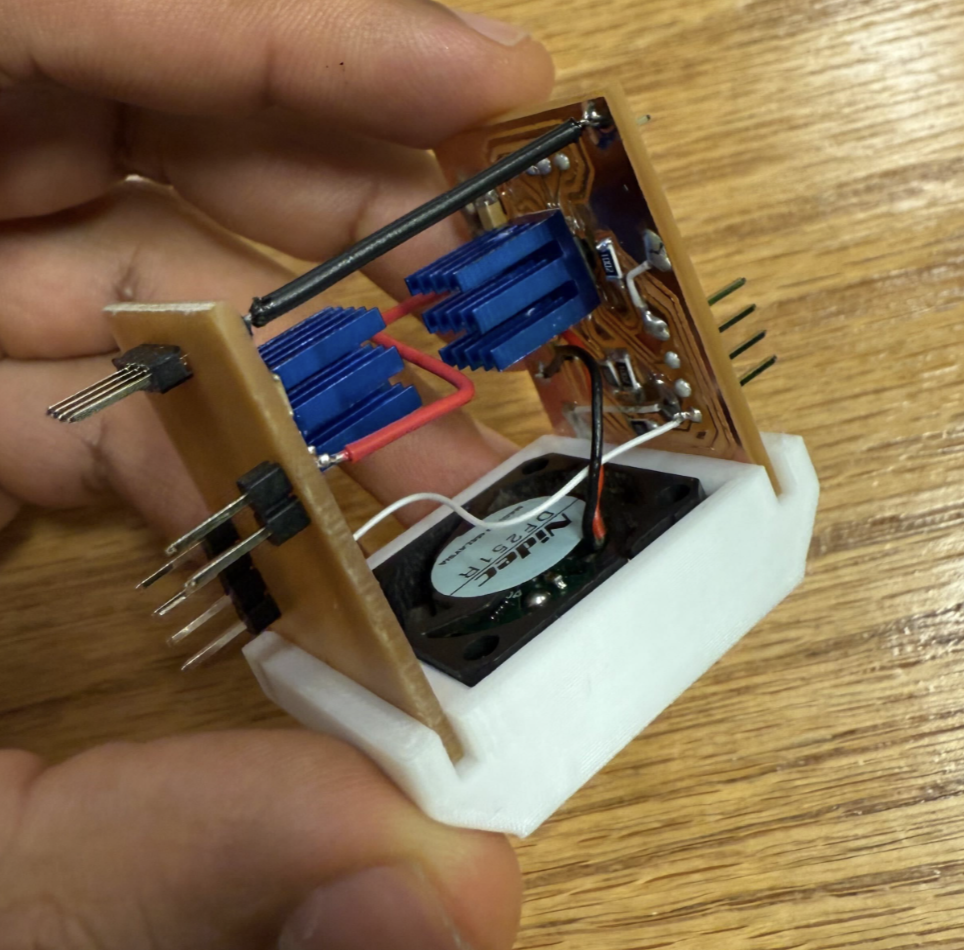
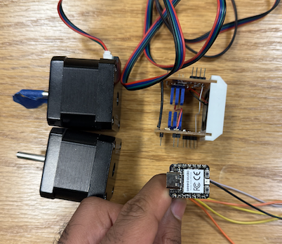
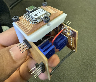
}Project Update - I finished the electronics. It is a redone version of by stepper motor driver but made more compact and I made two of them one for each stepper. I also lost the KiCAD files for the output weeks device, and I had to redo the PCB schematic and layout again - but it was good practice.
Previously the cooling from the heat sink wasn’t enough so I 3d printed a fan enclosure and the fan is connected to the power, so when the board is powered, the fan automatically turns on. Jessy gave me a fan from a pile of fans. The black wire connecting both boards is for ground, and red is power, and white is for the the logic ground.
Project Update - I visualized the segments in their folded form via ChatGPT help: https://chatgpt.com/share/69399087-80dc-8007-aa10-39f6f0458947
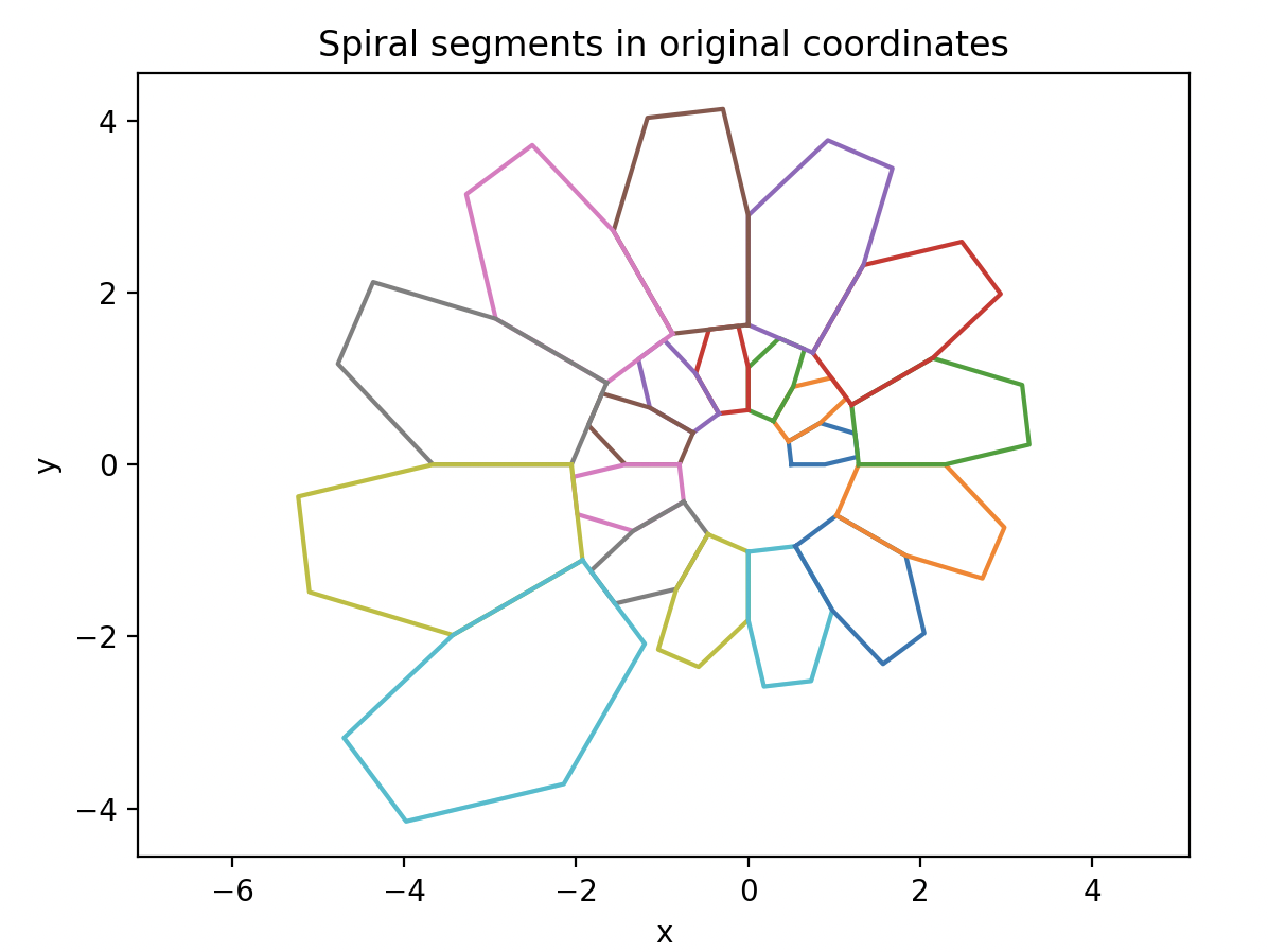
And it looked fine, and then I realized. The problem was I had the segments on backwards previously!
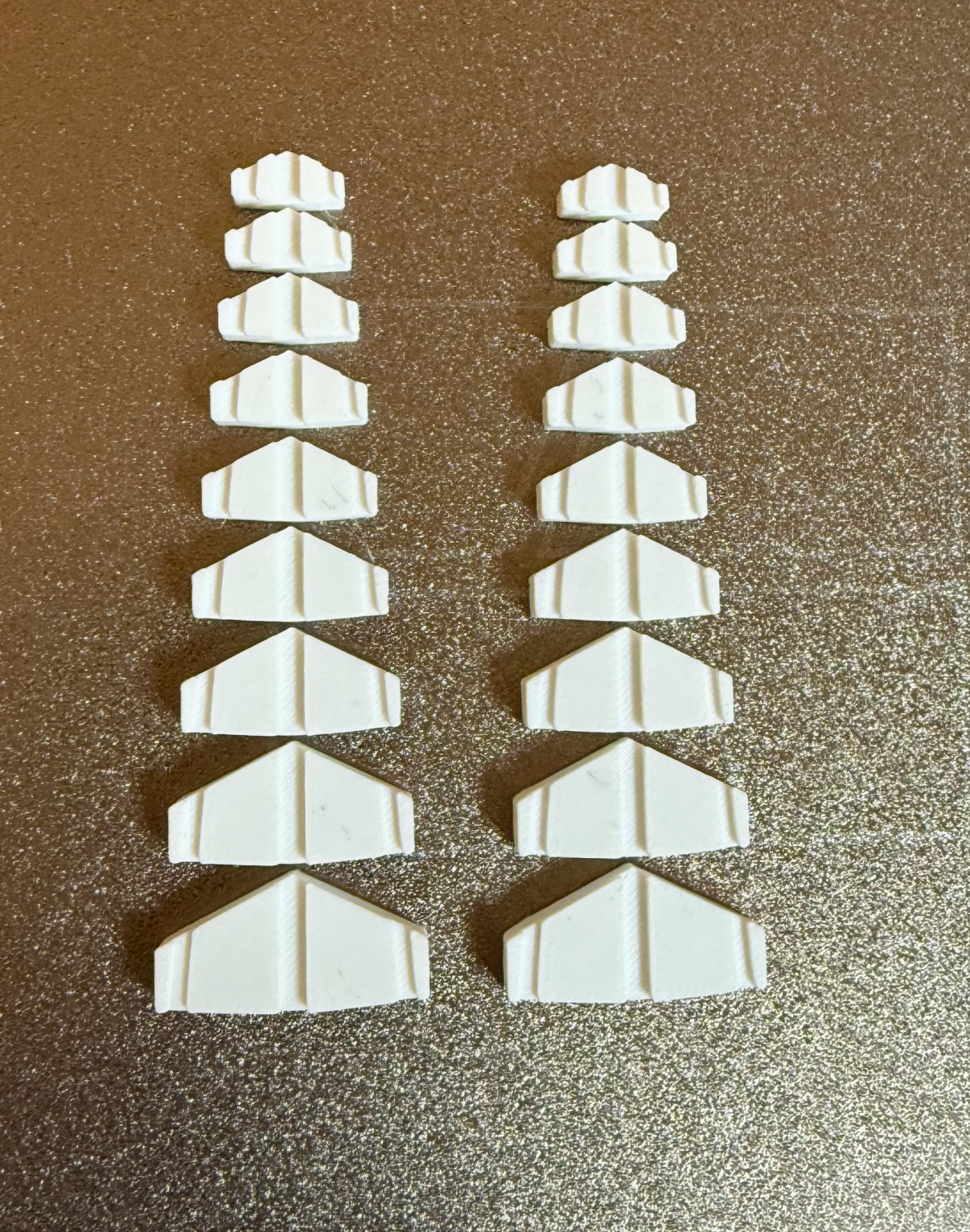
I then printed them out for the full size version.
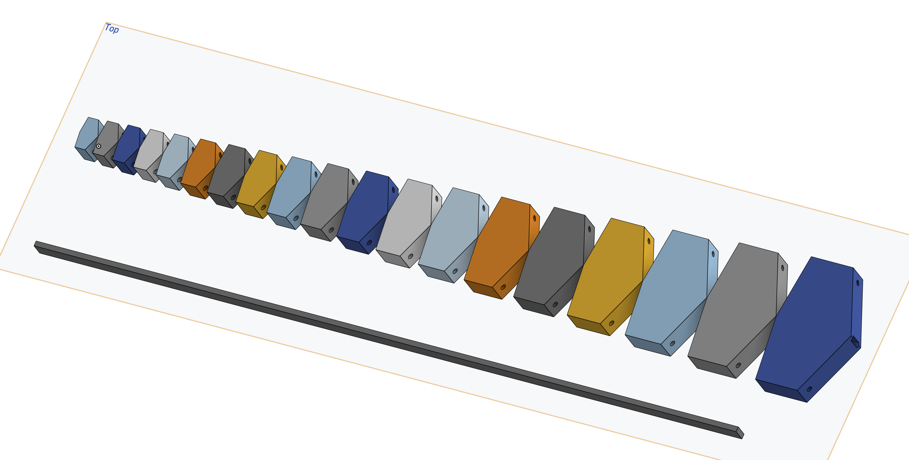
The final code is uploaded to the github linked here. The visualization from running python viz.py and running python main_v2.py will output a single DXF file.
Here is the file, and a visualization. The final code and the visualization code was also made using ChatGPT - here log link : https://chatgpt.com/share/69399087-80dc-8007-aa10-39f6f0458947
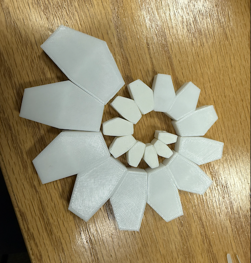
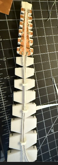
I printed it to have a thickness of 1cm, and I also added holes after extruding them for the elastic core and the cables on each side. Notice the color difference in the printed parts, Anthony recommended that I print in multiple batches in case there is a printer failure. The base parts that are more reflective is PETG, and the matte white top smaller parts are PLA.
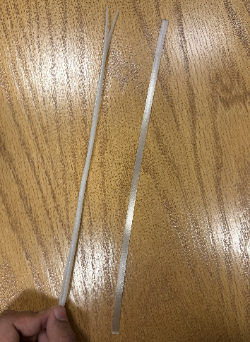
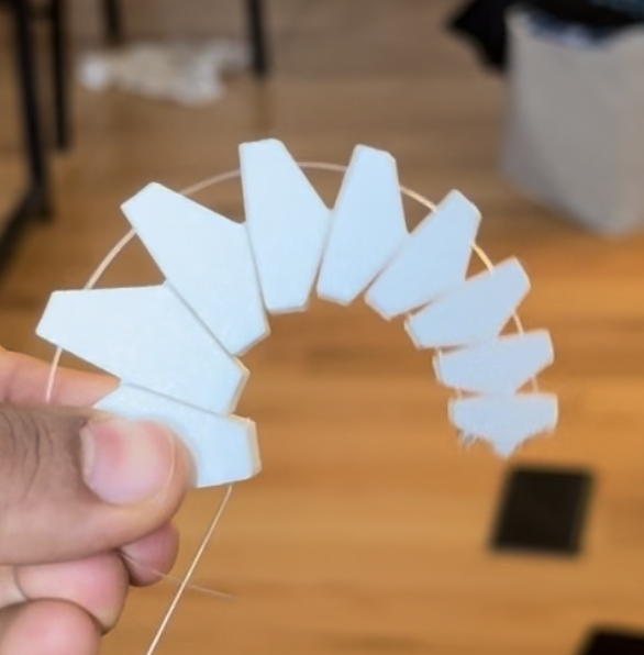
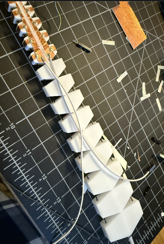
This is the TPU core, and it was actually way too floppy. So then I had to figure out an alternative solution. When walking across the machine shop, I spotted large zip-tie cables, and it was almost the right size. So I took 2 of them and initially tried to glue them together with hot glue, but that didn’t work because the lengths are different when its bent (the outer one will stretch more than the inner). So then I realized there is no need to glue them, and I just ended up leaving them free. I did have to sand them down because the hole in the segment is 2mm wide.
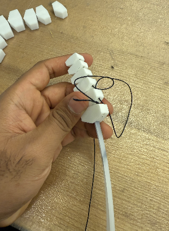
After that I started to thread the segments using Kevlar thread that Anthony provided me.
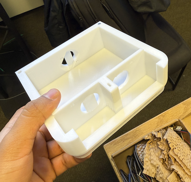
So now that the segments and the “arm” is done, the next step was to build the enclosure.
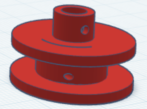
I was thinking of this placement, because it is compact. I then proceeded to look at existing stepper motor pulleys/spool to pull the thread.
I first printed this existing design: https://www.printables.com/model/237994-nema-23-stepper-motor-spool#preview.file.4rjtY
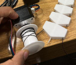
But this design had a problem, it was using a screw for the tensioning and the hole itself was a circle. So when I ran the stepper motor to pull the arm, when there was a lot of tension - the screw got pushed out. So this design clearly isn’t going to work for high load applications. I needed the print to have a notch for the flat part of the stepper motor’s flat side. I then found this design: https://www.thingiverse.com/thing:1794
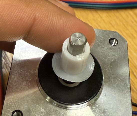
I modified it in tinker cad to just print the hole - I used tinkercad to remove the rest of part quickly. I show it to Anthony and we both agreed it was too loose - but the shape was right I just need to tighten the tolerance up more. I designed the full part next, and also added a tensioning M2 screw.
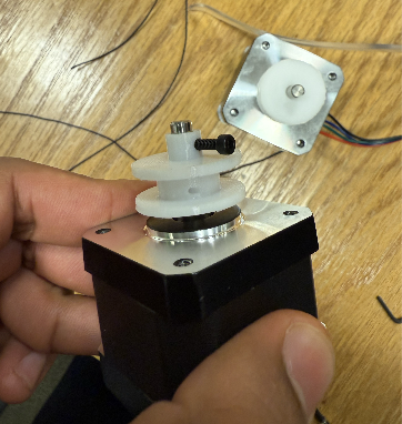
I used TinkerCad for this part just because I find it faster for making small parts that don’t require a lot of measurements. After I printed it out - it worked perfectly. The next step was the enclosure for the base.
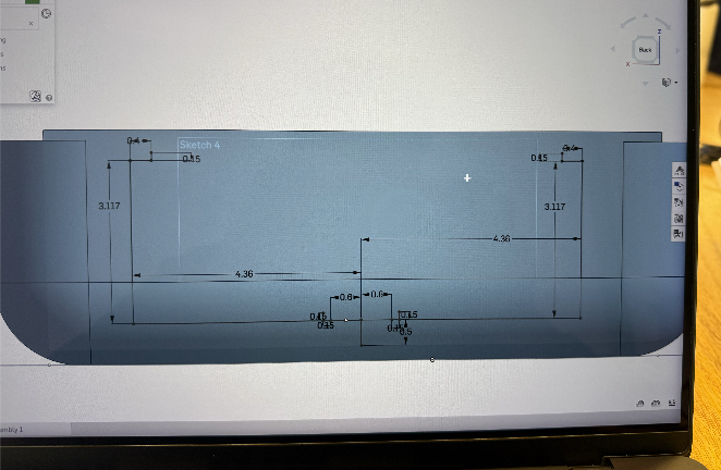
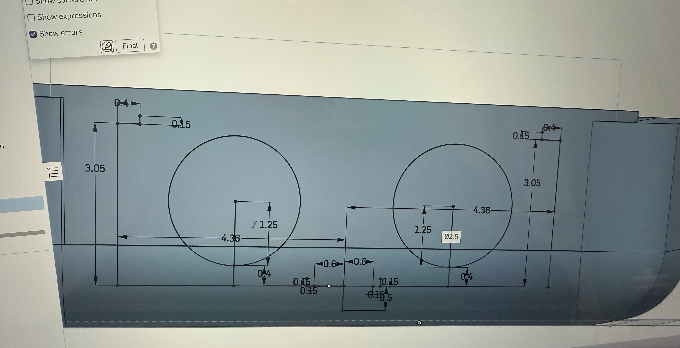

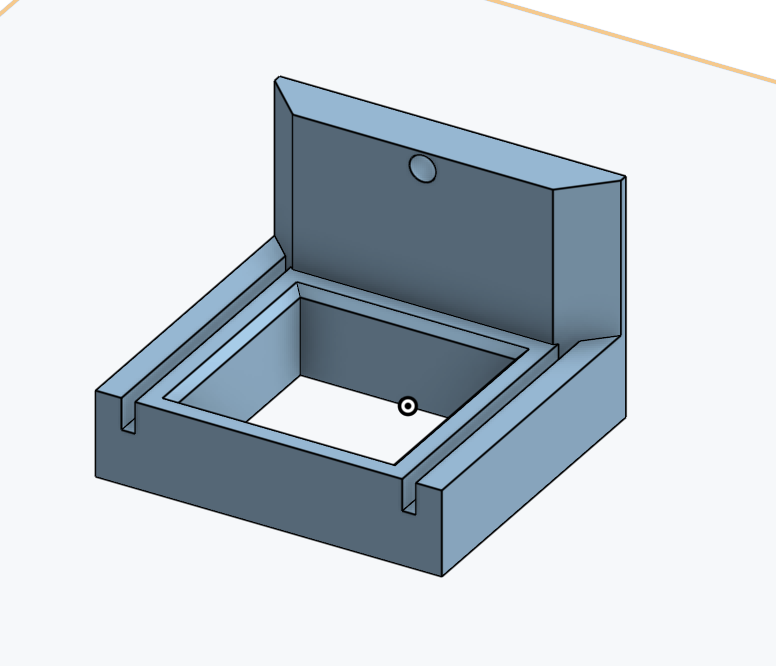
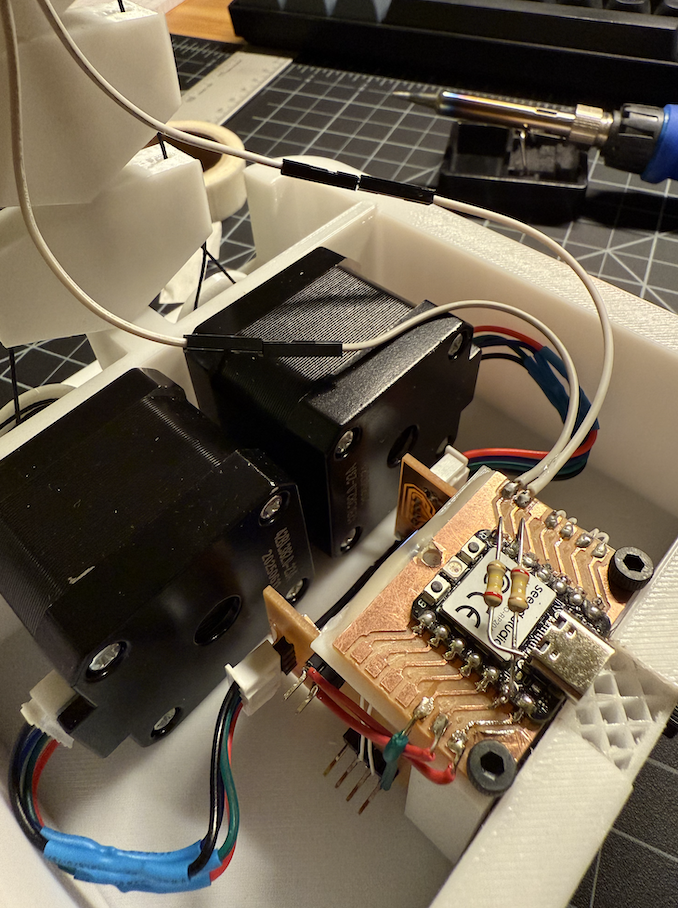
I did parametric design in OnShape. I designed it to use M3 screws to hold the motors and the fan. In addition, I decided instead of having the Xiao and the stepper motor driver to be side by side, I could save space by stacking them. I modified the original motor driver case to have a spot to mount the xiao PCB using M3 screws. I had to drill the PCB after that because I didn’t know PCB’s can’t be threaded (oops).
This worked great, I made a simple PCB for the XIAO for me to solder the pins. However, I ran into an issue. The stepper motor pins started to wiggle and eventually came loose - ripping the traces. I think the reason was because I overheated those traces.
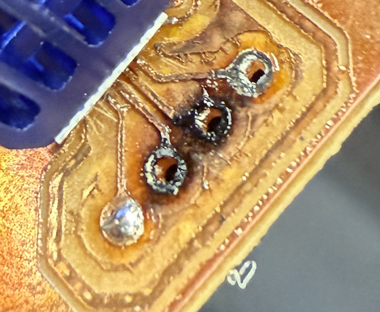
I spent hours trying to directly solder the stepper’s wires through those holes and I succeeded at that but then the board still didn’t work. After doing continuity tests I found that there was a short between on of the IC’s pins and ground. Me, Jessy and Anthony all tried to find the short and we couldn’t - and Anthony suggested that it might be an internal short. At this point many hours were spent trying to save this board but I decided just to make a new one.
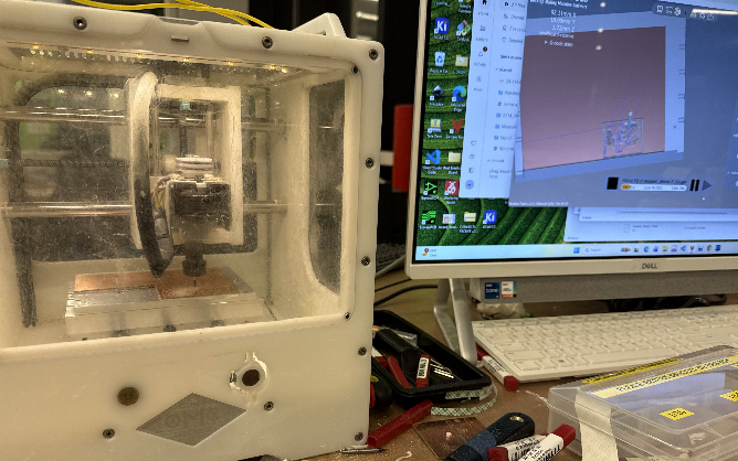
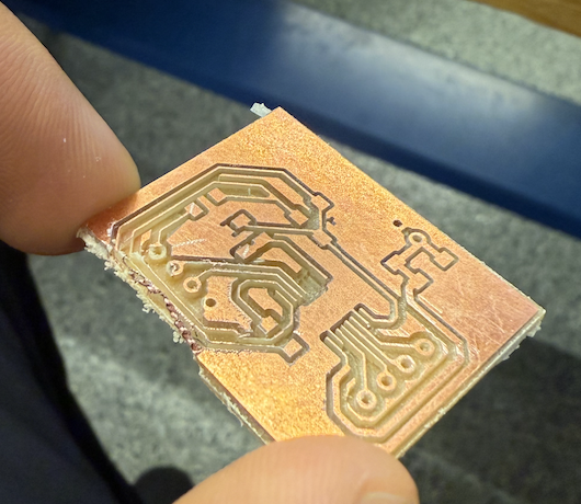
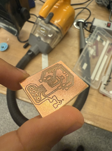
When milling the board popped out! Anthony quickly pressed the E-stop button. The reason the board popped out was because I used someone else’s existing copper pad and the sticky tape just lost its grip. So I took a fresh copper board and milled it.

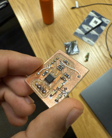
This time since it was around my fifth or sixth time making this same stepper motor driver, I wanted to make sure each step was done perfectly and not deal with short problem. So for this board, I carefully took a solder paste syringe, and laced each trace under the microscope. This was a very slow and careful process since each trace is 0.24 mm wide. What I did was I put a blob of solder paste in the center pad, and I just dipped the metal tip of the syringe into that blob and brushed each trace carefully.
This worked perfectly in the first try.
After that my print finished, and I added magnets from the spare Prusa repare parts that Anthony provided me. I later super glued them in.
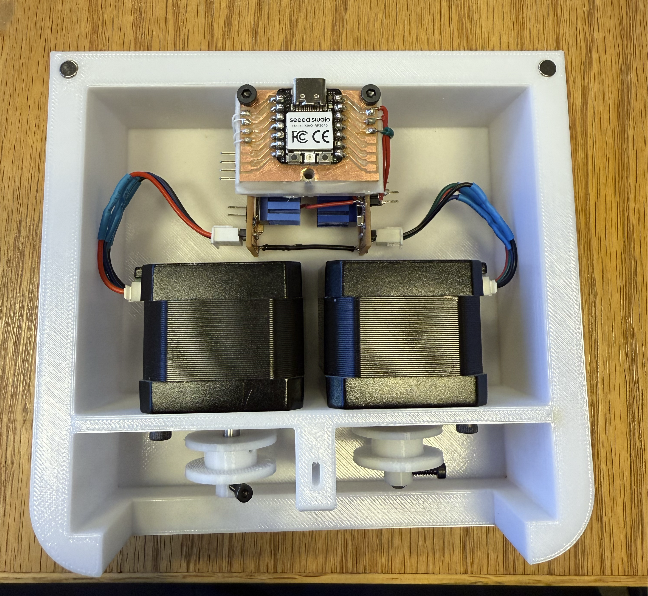
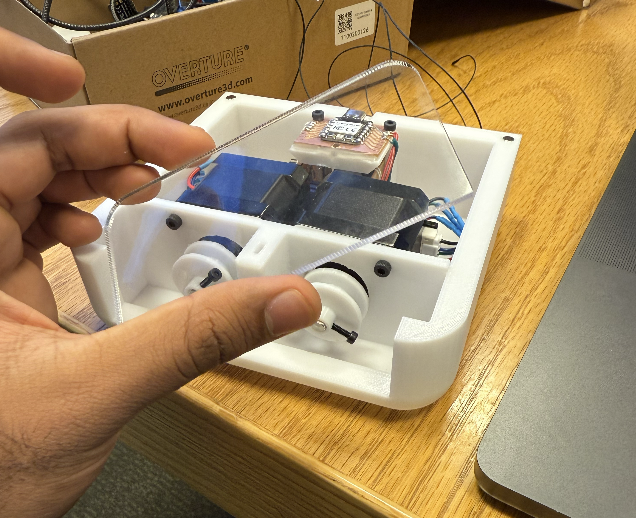
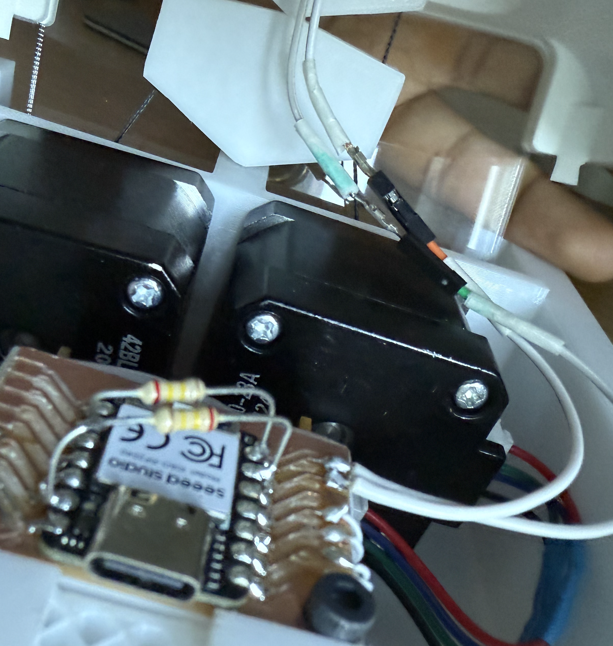
The steppers fit in well and I could see my project start to come together finally. For the stepper motor wires, I cut them on both ends and resoldered them and added heatshrink tubing and used the hot air gun for that. However, there was one minor issue, the USB C cable was too thick and there wasn’t enough clearance to connect to the xiao. So I asked dave if we could mill this part out and he milled it using the Bridgeport J-Head Mill.
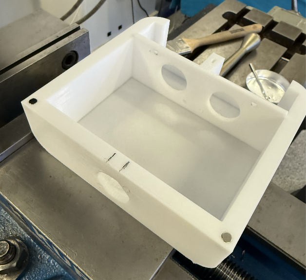
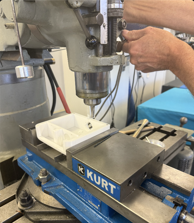
Now you can see the infill - but it got the job done.
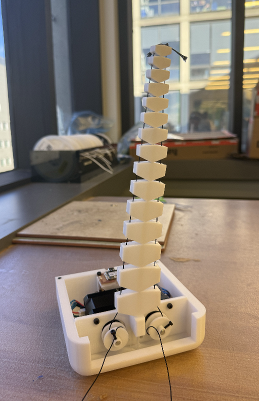
Here is a status update picture. The next steps are making a window out of acrylic and a cover too.
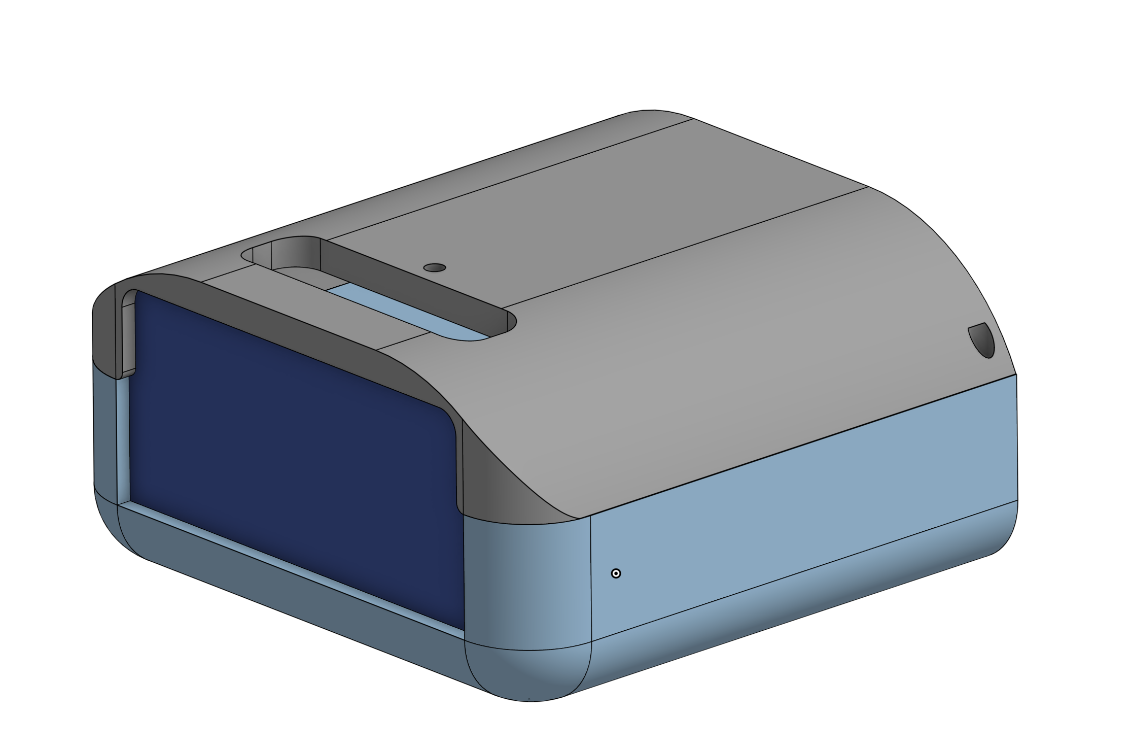
The dark blue panel is the window and the grey part is the cover. I really like how I can design multiple parts in OnShape - this project definitely improved my CAD skills. I then exported the panel as a DXF. Viewer is : https://sharecad.org/
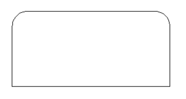
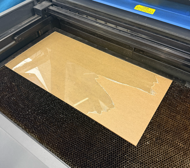
I laser cut it with Dave just to make sure things are safe since I haven’t laser cut acrylic before. The thickness of the acrylic is 3mm.
For my input - I decided to make the arm react to touch. This when my internal image of this being the original arm pivoted to it being more like a reactive plant that jerks when you touch it.

I discussed with Anthony and I went with doing capacitive touch. I followed this article: https://www.digikey.com/en/maker/tutorials/2021/how-to-add-capacitive-sensing-to-any-arduino-project and used a 240k resistor. However, the code they provided didn’t work because the library include <CapacitiveSensor.h> isn’t supported for the RP2040. I then asked ChatGPT to help with the code to fix this
(I included the video of the transcript since this was a temporary chat)
Then using ChatGPT again - the code now senses two pads: https://chatgpt.com/share/693f6228-87e4-8007-a3c4-9ad9f8d72b13
// Two-pin capacitive touch for RP2040 (Arduino core) - MADE WITH CHATGPT
// Hardware per pin: touch pad -> PIN, ~1M resistor PIN -> GND (I used a 240k)

const int PIN1 = D6;
const int PIN2 = D5;

const int SAMPLES = 30;

uint32_t baseline1 = 0;
uint32_t baseline2 = 0;

uint32_t readCapRaw(int pin) {
  uint32_t total = 0;

  for (int i = 0; i < SAMPLES; i++) {
    // Charge the pad
    pinMode(pin, OUTPUT);
    digitalWrite(pin, HIGH);
    delayMicroseconds(5);

    // Float the pin and time discharge through ~1M pulldown
    pinMode(pin, INPUT);

    uint32_t t = 0;
    while (digitalRead(pin) == HIGH && t < 2000) {
      t++;
    }
    total += t;
  }

  return total;
}

void setup() {
  Serial.begin(9600);
  delay(200);

  // Establish baselines (not touched)
  uint64_t sum1 = 0;
  uint64_t sum2 = 0;

  for (int i = 0; i < 100; i++) {
    sum1 += readCapRaw(PIN1);
    sum2 += readCapRaw(PIN2);
    delay(5);
  }

  baseline1 = sum1 / 100;
  baseline2 = sum2 / 100;

  Serial.print("Baseline1 (D6) = ");
  Serial.println(baseline1);
  Serial.print("Baseline2 (D5) = ");
  Serial.println(baseline2);
}

void loop() {
  uint32_t v1 = readCapRaw(PIN1);
  uint32_t v2 = readCapRaw(PIN2);

  int32_t d1 = (int32_t)v1 - (int32_t)baseline1;
  int32_t d2 = (int32_t)v2 - (int32_t)baseline2;

  Serial.print("D6 raw=");
  Serial.print(v1);
  Serial.print(" delta=");
  Serial.print(d1);

  Serial.print(" | D5 raw=");
  Serial.print(v2);
  Serial.print(" delta=");
  Serial.println(d2);

  // Simple touch thresholds (tune independently if needed)
  if (d1 > 50) {
    // D6 touched
  }
  if (d2 > 50) {
    // D5 touched
  }

  delay(50);
}
I will explain the code now. I used ChatGPT to understand the physics as well : log is here https://chatgpt.com/share/693f6fad-4c9c-8007-a29c-95a3078845ca. In my own words (and I will not claim its 100% accurate since I am not an EE person).
When objects like a finger come closer to the copper pad - there is more capacitance since the finger is a closer connection to ground. This allows the copper pad to store more charge by this equation . Then the code will discharge the pad by floating the same pin, and the current will go through the resistor and since the value of the resistance is larger (240k Ohms) then it takes longer for the voltage to drop - and that time is measurable by the RP2040. So when a finger is in contact - the capacitance goes up - then time for the current to discharge will also increase and the time that the pin still reads HIGH (determined by the voltage) is going to take longer.
Then it was time to add the copper to the top part of the segments. One connected copper pad for each side - so the robot can sense which direction the touch is coming from.
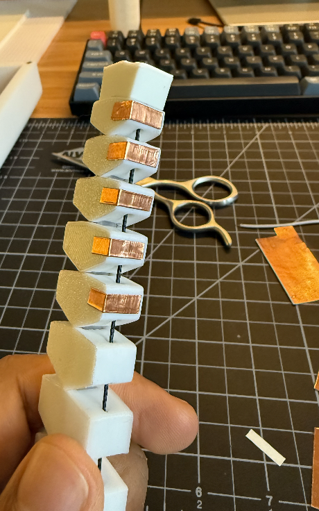
I cut 0.4 cm x 1.5 cm copper rectangles and used the adhesive on the back to stick them.

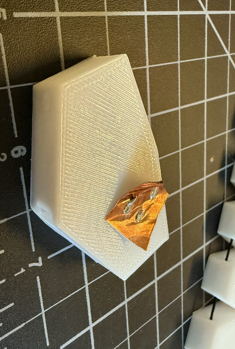
Now I was curious - can I solder on top of them - so I used an unused segment and stuck a square copper on top and added some solder to it - and surprisingly nothing happened.
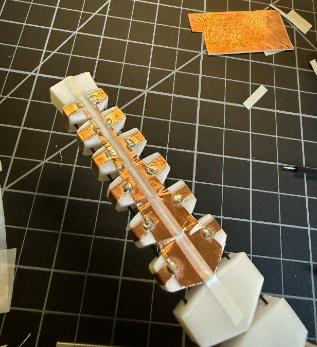
I soldered some connecting copper and wires as well.
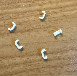
I then printed small wire guides on PLA using my personal Bambu A1. Then I needed to attach the two wires to the Xiao. To do this I soldered two female jumper cables to the xiao board and directly soldered the 2 240k ohm resistors over the xiao, connecting each digital output pin (D5, D6) to ground. However there was a problem, the plastic casing around the header pins was too large to fit over the cover’s hole. So I decided to remove the casing and just add some Muji tape as some insulation as you can see on the right hand image below.

I also printed the cover on my Bambu A1, and I added matte white tape over the curves because I printed the cover upside down since it was 2x faster due to the less support needed - but the angle of the curve was hard for the printer and it was not clean so I covered it up with a similar color tape. I used the Bambu pla matte white for this. Now it was just time to combine the stepper code and the touch code into an interesting behavior. I worked with ChatGPT for this, where I first architected how I wanted the program to be designed. Here is the log: https://chatgpt.com/share/693f7269-6698-8007-b097-56525ebfaf13 - the code is attached at the bottom
I then manually tuned the parameters of how many steps the hitting motion should take as well as the delay time.
And that concludes my final project!
For Logistics here are the answers to the questions.
 What does it do?
 Who's done what beforehand?
 What sources did you use?
 What did you design?
 What materials and components were used?
 Where did they come from?
 How much did they cost?
 What parts and systems were made?
 What tools and processes were used?
 What questions were answered?
 What worked? What didn't?
 How was it evaluated?
 What are the implications?
what does it do? - this plant like robot sways back and forth like a grass in the wind until it senses you have touched it. When touched it will hit your finger, and after that resume swaying.
what's done what beforehand? - this project is largely influenced by the paper SpiRobs https://arxiv.org/pdf/2303.09861 as aforementioned, I wanted to replicate that. However, due to the friction of the kevlar and the 3D printed segments, the arm couldn’t fully loop around, and I pivoted the project to model a plant instead. What sources did you use? - the main one was Anthony + ChatGPT. In addition some OnShape tutorials and articles that I linked.
What materials and components were used? Here are a list of parts I used.
First the ones from the inventory:
2 of the Nema 17 Stepper motors: https://www.amazon.com/Stepper-42x23mm-42BYGH-130mN-m-Printer/dp/B088BG2QFG/?th=1
couple squared cm of copper tape: https://www.3m.com/3M/en_US/p/d/b00041302/
M2, M3 screws.
Jumper wires.
2 of the TI DR8428 stepper motor drivers: https://www.digikey.com/en/products/detail/texas-instruments/DRV8428PWPR/13563046
1206 formfactor capacitors (4 x 10 uf, 2 x 1uf, 2 x 10N)
https://www.digikey.com/en/products/detail/murata-electronics/GRT31CC8YA106ME01L/5416847
https://www.digikey.com/en/products/detail/tdk-corporation/C3216X7R1H105K160AB/569049
https://www.digikey.com/en/products/detail/tdk-corporation/C3216X7R2A104K160AA/513967
1206 formfactor resistors (10 x 10k) https://www.digikey.com/en/products/detail/yageo/RC1206FR-0710KL/728483
2 x through hole 240k ohm resistors
3x copper PCB board.
2x heat sink
Lead free solder
Magnets (Anthony had a spare pack from a Prusa Replacement)
Heat Shrink Tubing
DC Fan - from an assortment of random fans.
Xiao RP2040: https://www.digikey.com/en/products/detail/seeed-technology-co-ltd/102010428/14672129
header pins - male row
Where did they come from + How much did they cost?
The costs are on the linked websites - overall the build will be within ~100$
What parts and systems were made? - I CAD designed most parts from scratch. I developed (with ChatGPT) and automated DXF generator which automated making the segments for me. The PCBs were also primarily made from scratch - with help from Anthony.
What tools and processes were used? - I used the following tools:
- A personal Bambu A1
- PLA filament + TPU filament (but didn’t use it for the final version)
- Prusa Core One 3D printer
- Bridgeport J-Head Mill
- Othermill V2 Desktop Mill
- Hot Glue Gun
- Soldering Iron
- Universal Laser cutters 60 and 75 watt
The processes, was milling (PCB and the Plastic), 3D printing, soldering, gluing, drilling, laser cutting.
What questions were answered? + What worked? What didn't?
Over the course of this build, I figured out what it actually takes to turn a SpiRobs-style tendon spiral from “looks great in a paper/video” into something I can physically make myself.
A lot of it was learning what fails first in the real world (core stiffness vs floppiness, friction in the 3D printed segments with the kevlar - preventing it from fully curling, and the fishing/Kevlar line, and ripping out header pins ).
In addition, the stepper speeds likely need more tuning. As the segments curl, the inner and outer Kevlar strings don’t change length symmetrically, which can increase tension and strain the motors. In the future, I want to model this more explicitly and compute how much cable to release vs. pull as a function of curvature, rather than driving both steppers with the same step profile.
How was it evaluated? + What are the implications? - The evaluation was simple - just qualitative assessment if the desired behavior was made. The implications are - the choice of materials is very important at high stress areas - specifically when you pull the kevlar a lot to curl the arm - it puts a lot of stress on the segments. The initial designed actually ripped through the segments - which is why I had to make them in one go and not glue 2 halves together.
The files for all the parts are here:
final code:
// modified from neils stepper code and made with ChatGPT - see logs from website

// === Stepper pins (XIAO RP2040) ===
// First Stepper
#define DIR1  D0
#define STEP1 D1

// Second Stepper
#define DIR2  D3
#define STEP2 D2

// Pulse width (high time). Speed is controlled mainly by delay_low passed into go_to.
#define DELAYHIGH_US 10

// === Capacitive touch pins ===
// (By convention here: PIN_LEFT returns 1, PIN_RIGHT returns 2)
const int PIN_LEFT  = D5;
const int PIN_RIGHT = D6;

const int SAMPLES = 30;

// Touch threshold on delta (raw - baseline)
const int32_t TOUCH_THRESH = 500;

uint32_t baseline_left  = 0;
uint32_t baseline_right = 0;

// Global absolute position (steps)
long pos = 0;

// ---- Capacitive read ----
uint32_t readCapRaw(int pin) {
  uint32_t total = 0;

  for (int i = 0; i < SAMPLES; i++) {
    // Charge the pad
    pinMode(pin, OUTPUT);
    digitalWrite(pin, HIGH);
    delayMicroseconds(5);

    // Float the pin and time discharge through ~1M pulldown
    pinMode(pin, INPUT);

    uint32_t t = 0;
    while (digitalRead(pin) == HIGH && t < 2000) {
      t++;
    }
    total += t;
  }

  return total;
}

// Returns 0 (no touch), 1 (left), 2 (right)
int checkTouchOnce() {
  uint32_t vL = readCapRaw(PIN_LEFT);
  uint32_t vR = readCapRaw(PIN_RIGHT);

  int32_t dL = (int32_t)vL - (int32_t)baseline_left;
  int32_t dR = (int32_t)vR - (int32_t)baseline_right;

  // If both trigger, pick the larger delta (you can change this policy)
  bool leftTouched  = (dL > TOUCH_THRESH);
  bool rightTouched = (dR > TOUCH_THRESH);

  if (leftTouched && rightTouched) {
    return (dL >= dR) ? 1 : 2;
  } else if (leftTouched) {
    return 1;
  } else if (rightTouched) {
    return 2;
  }
  return 0;
}

// Step both steppers once (in sync)
void stepBothOnce(uint32_t delay_low_us) {
  digitalWrite(STEP1, HIGH);
  digitalWrite(STEP2, HIGH);
  delayMicroseconds(DELAYHIGH_US);

  digitalWrite(STEP1, LOW);
  digitalWrite(STEP2, LOW);
  delayMicroseconds(delay_low_us);
}

// go_to(desired_pos, delay_low_us, check_touch)
// returns: 1 left touch, 2 right touch, 0 if reached target w/ no touch
int go_to(long desired_pos, uint32_t delay_low_us, bool check_touch) {
  if (desired_pos == pos) return 0;

  int dir = (desired_pos > pos) ? +1 : -1;

  // Direction convention:
  // dir=+1 -> DIR HIGH, dir=-1 -> DIR LOW
  digitalWrite(DIR1, (dir > 0) ? HIGH : LOW);
  digitalWrite(DIR2, (dir > 0) ? HIGH : LOW);

  while (pos != desired_pos) {
    // Optional touch check per step
    if (check_touch) {
      int td = checkTouchOnce();
      if (td != 0) {
        return td; // abort early on touch
      }
    }

    // One step
    stepBothOnce(delay_low_us);

    // Update absolute position
    pos += dir;
  }

  return 0;
}

void setup() {
  // Stepper setup
  pinMode(STEP1, OUTPUT);
  pinMode(DIR1, OUTPUT);
  pinMode(STEP2, OUTPUT);
  pinMode(DIR2, OUTPUT);

  digitalWrite(STEP1, LOW);
  digitalWrite(DIR1, LOW);
  digitalWrite(STEP2, LOW);
  digitalWrite(DIR2, LOW);

  Serial.begin(9600);
  delay(200);

  // Establish baselines (not touched)
  uint64_t sumL = 0;
  uint64_t sumR = 0;

  for (int i = 0; i < 100; i++) {
    sumL += readCapRaw(PIN_LEFT);
    sumR += readCapRaw(PIN_RIGHT);
    delay(5);
  }

  baseline_left  = sumL / 100;
  baseline_right = sumR / 100;

  Serial.print("Baseline LEFT (D6)  = ");
  Serial.println(baseline_left);
  Serial.print("Baseline RIGHT (D5) = ");
  Serial.println(baseline_right);

  pos = 0; // origin
}

void loop() {
  // Very wide, slow, organic sway
  const long A = +2000;
  const long B = -2000;

  // Speed envelope (microseconds)
  const uint32_t FAST_US = 1;    // fastest at mid-swing
  const uint32_t SLOW_US = 10;   // slowest near the ends
  const int SEGMENTS = 10;

  auto ease = [](float t) -> float {
    return t * t * (3.0f - 2.0f * t); // smoothstep
  };

  auto handleTouch = [&](int td) {
    // td: 1 = left, 2 = right
    // Define "direction" in terms of pos:
    // +pos is toward A (right in your code’s convention), -pos toward B.
    // If left touch => lunge negative direction, if right touch => lunge positive direction.
    int hitDir = (td == 1) ? -1 : +1;

    Serial.print("Touch detected. dir=");
    Serial.println(td);

    // Step 1: back off 40 away from the touch direction
    // "Away from touch direction" means opposite of hitDir
    long backTarget = pos - hitDir * 1050;   // opposite direction
    go_to(backTarget, 30, false);           // slower retreat, no touch check

    // Small pause (optional, makes it feel intentional)
    delay(250);

    // Step 2: fast lunge 500 toward the touch direction
    long hitTarget = pos + hitDir * 3500;
    go_to(hitTarget, 5, false);            // fast attack, no touch check

    // Optional settle pause
    delay(80);
  };

  // ---- swing to +A ----
  for (int i = 0; i <= SEGMENTS; i++) {
    float t = (float)i / (float)SEGMENTS;
    float e = ease(t);

    long target = (long)lroundf((1.0f - e) * (float)pos + e * (float)A);

    float tri = 1.0f - fabsf(2.0f * t - 1.0f);
    uint32_t delay_us = (uint32_t)lroundf(SLOW_US - tri * (SLOW_US - FAST_US));

    int td = go_to(target, delay_us, true);
    if (td != 0) {
      handleTouch(td);
      break; // break out of this swing; next loop iteration resumes sway
    }
  }

  // ---- swing to -B ----
  for (int i = 0; i <= SEGMENTS; i++) {
    float t = (float)i / (float)SEGMENTS;
    float e = ease(t);

    long target = (long)lroundf((1.0f - e) * (float)pos + e * (float)B);

    float tri = 1.0f - fabsf(2.0f * t - 1.0f);
    uint32_t delay_us = (uint32_t)lroundf(SLOW_US - tri * (SLOW_US - FAST_US));

    int td = go_to(target, delay_us, true);
    if (td != 0) {
      handleTouch(td);
      break;
    }
  }
}
Acknowledgments - Anthony gets a huge shoutout for his help and free food! His patience is unbelievable, and I do not know how someone can multi task so much when there are multiple people saying “Hey Anthony …”. Operating systems should learn from Anthony’s scheduling algorithm. Also, I want to thank Neil for putting together this course - hands down it has been the best course at MIT, and in my life. I can imagine it takes a lot of effort from him and the staff - so I appreciate that and hopefully the course keeps going and inspiring more students to appreciate the physical world and the objects / tools we take for granted. After this course, I look a any manufactured object differently now.