Electronics Production
Firstly, let’s start with the references I used, the following includes the links I used to look up pinout diagrams, wiring the oled display, RGB led pinouts, and the code I used.
References
https://wiki.seeedstudio.com/XIAO-RP2040/https://how2electronics.com/getting-started-with-seeed-xiao-ble-nrf52840-sense/
https://circuitcellar.com/research-design-hub/addressable-rgb-leds/
https://chatgpt.com/share/68ea6f50-c64c-8007-bddb-b08c330d8194
https://chatgpt.com/share/68ea6f39-3894-8007-8c51-5b752f7cdb3b
https://downloads.cree-led.com/files/ds/h/HB-CLV1L-FKB.pdf
Acknowledgments
As usual I need to thank Anthony - he helped us with the group assignment and soldering my board, debugging it, and with some of the coding. In addition, there was another man there who helped me but I don’t know his name - he helped me with the PCB milling process.
Group Assignment
With Anthony we did the group assignment together of learning how to use the Bantam PCB milling machine. We learned about the different end mill bits, and we milled this board.
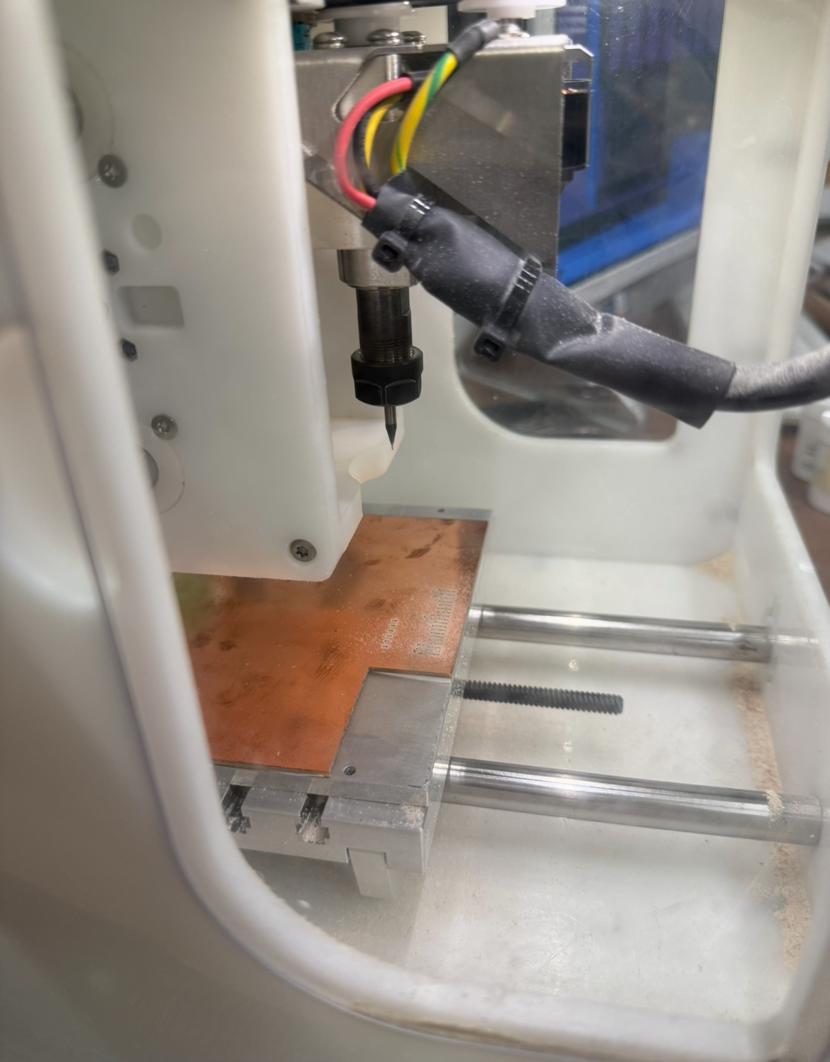
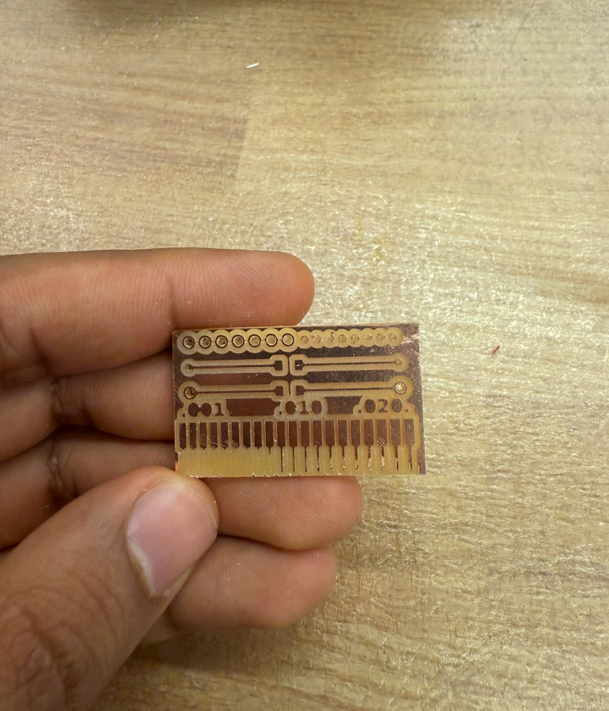
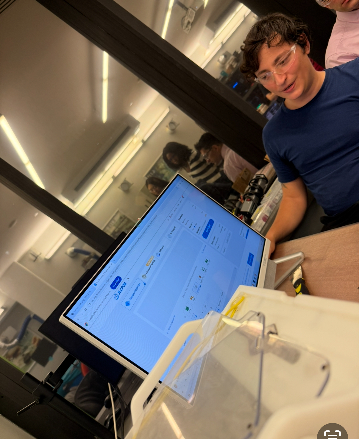
So around 0.01 seems to be the lowest we can go, but even that seems not robust enough for long term use. We also then sent a PCB to JLCPCB to explore the process of getting our designs fabbed by a professional service, and we explored the various settings such as color, material etc. We uploaded a blank design that we could use later on the laser etching machine.
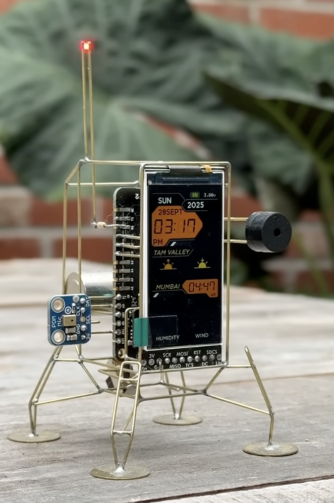
For my assignment I inspired by Mohit Bhoite, I especially liked this piece from him.
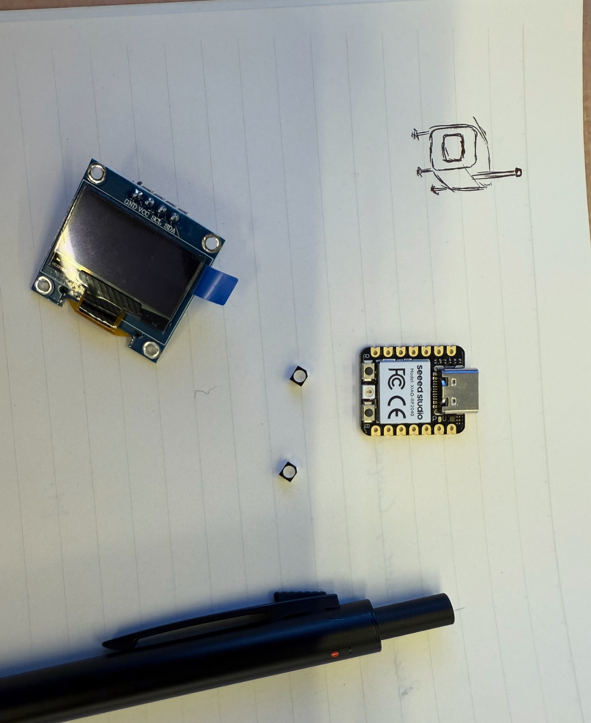
Therefore, I got to designing. I got the parts which are the xiao r2040, an OLED screen and an RGB led. I also drew a rough sketch of how II wanted it to look like.
Then I got to designing in KiCad.
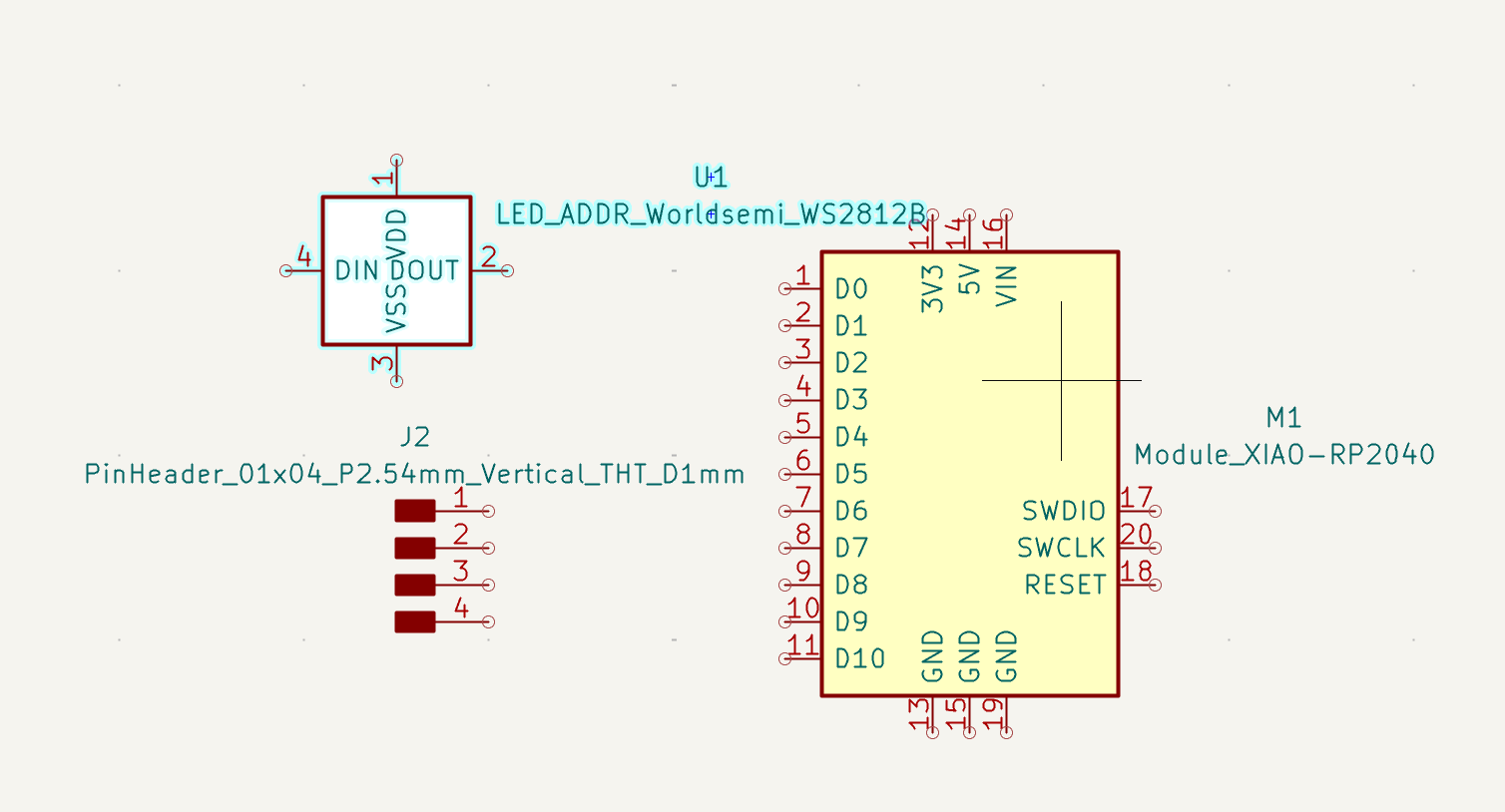
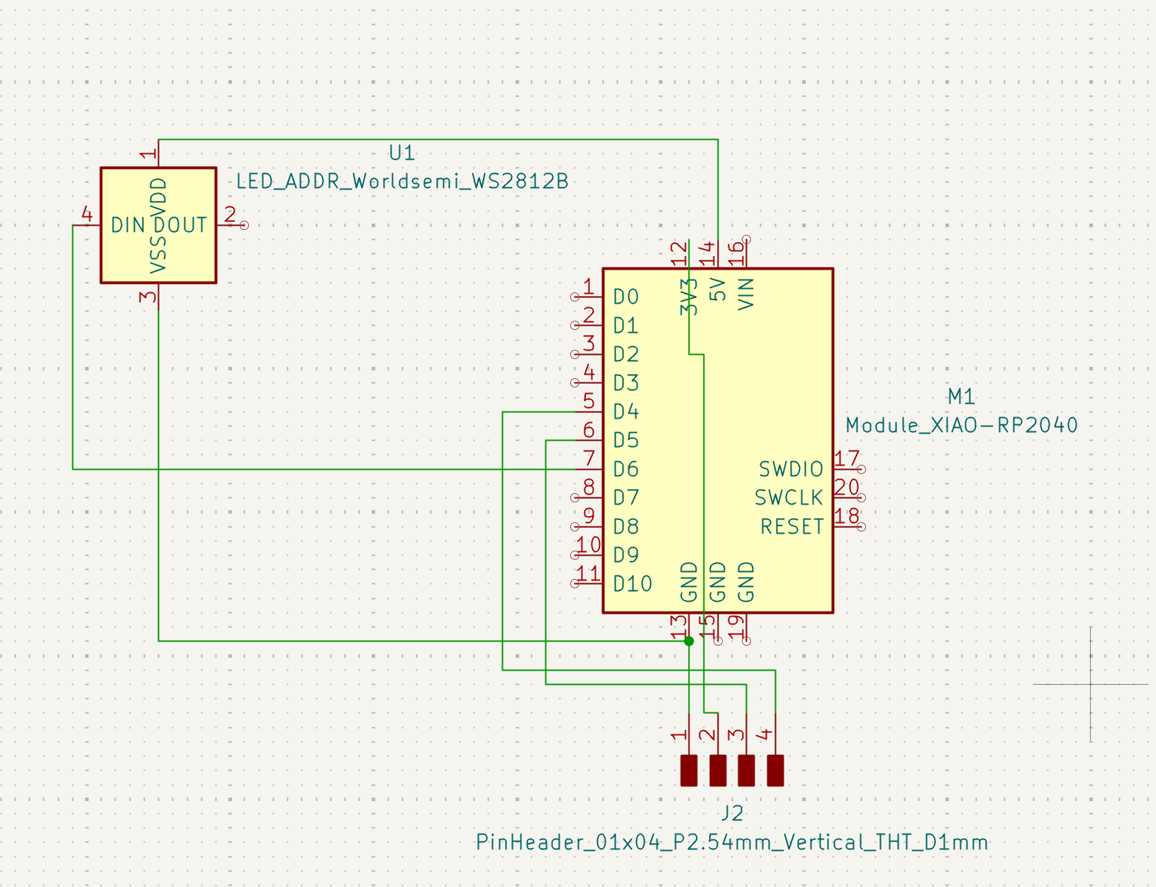
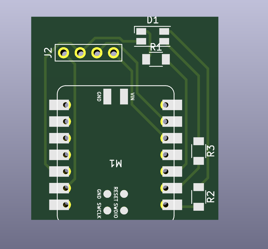
Laid out the parts, and then wired them based on the references I linked above.
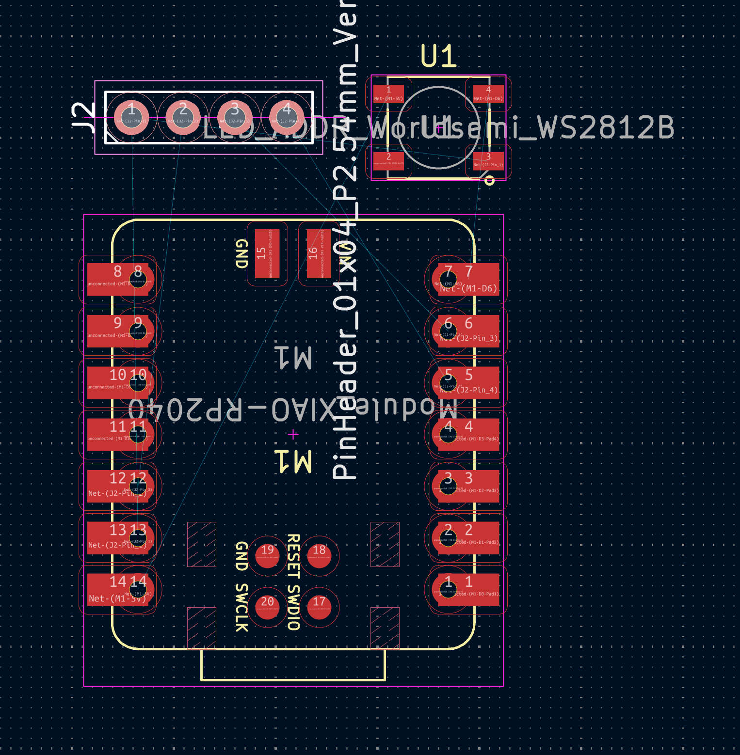
Then I spent some time routing all the wires. But then after looking at it closely I realized the LED is too large, and I choose the wrong part. Then I had to redo the LED.
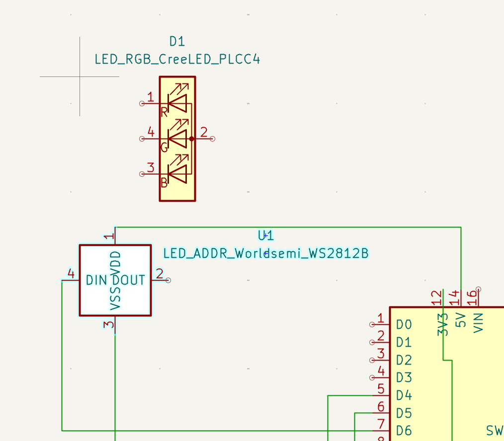
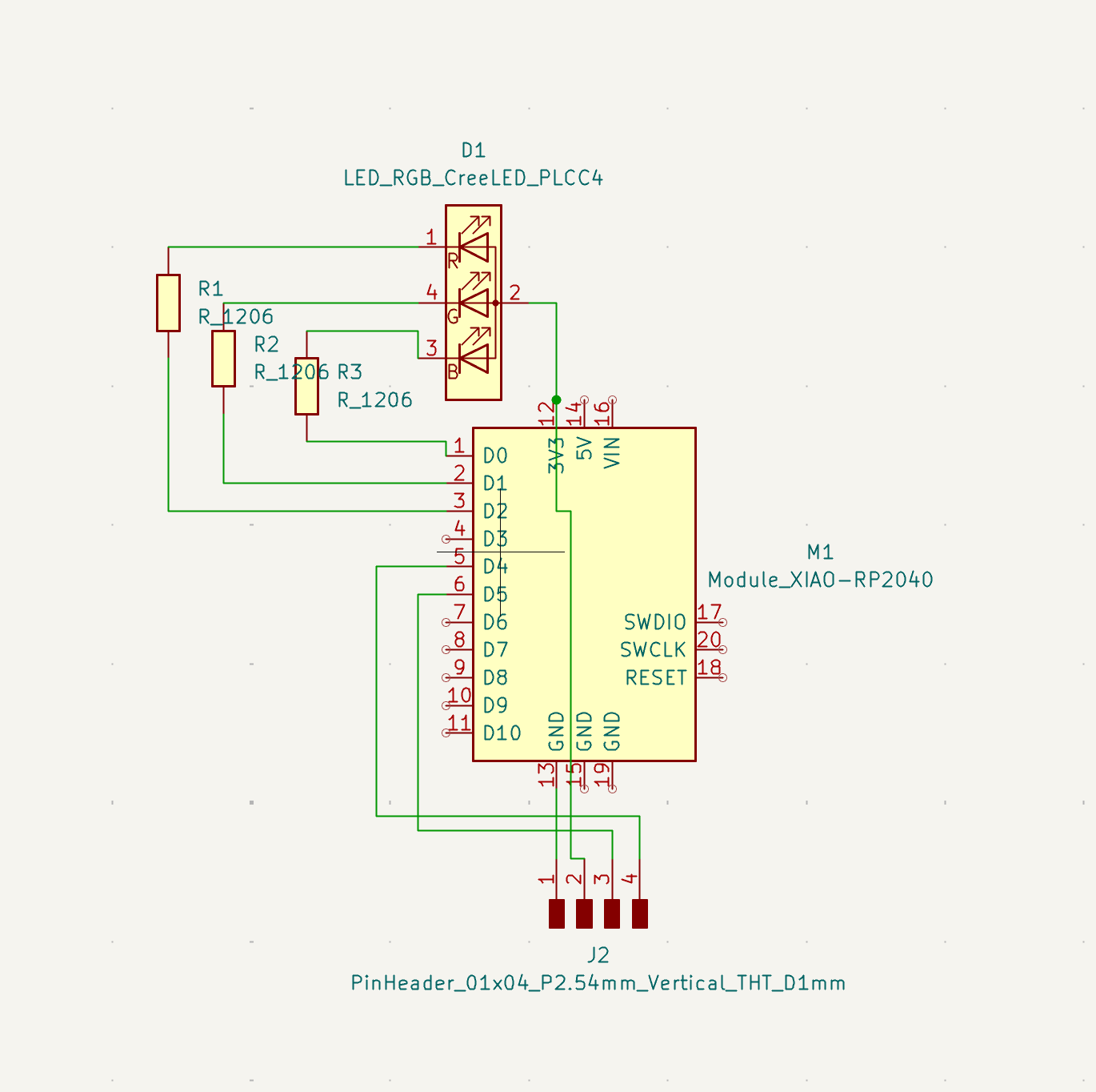
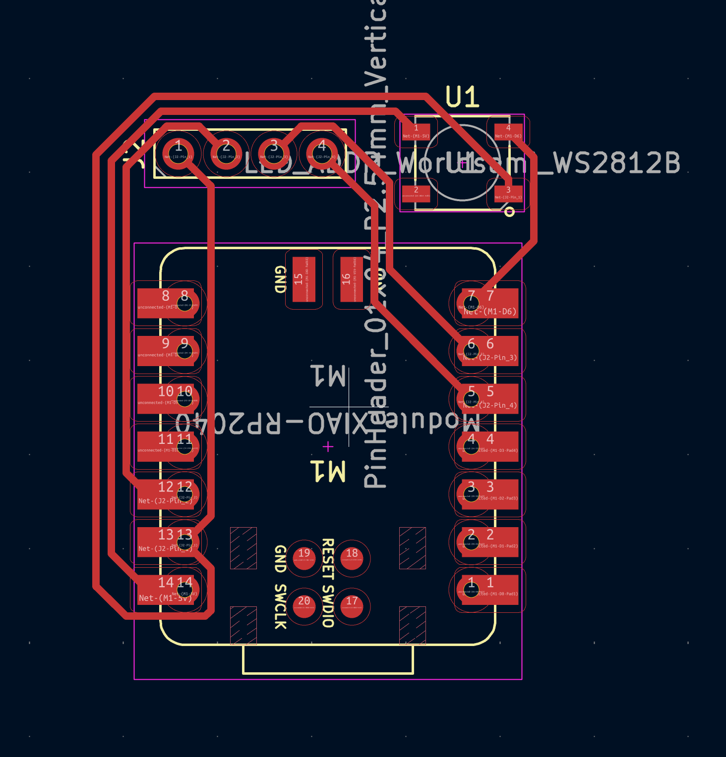
Here we have the correct RGB LED, from the Fab lab parts. It works by packing in a red, green, blue diode and they share the common anode. I added a resister for each cathode, and Anthony said the resister I was using (100 ohms) was going to make it too bright (he was later correct) . Then I routed it and here is is the viewer’s rendering. =
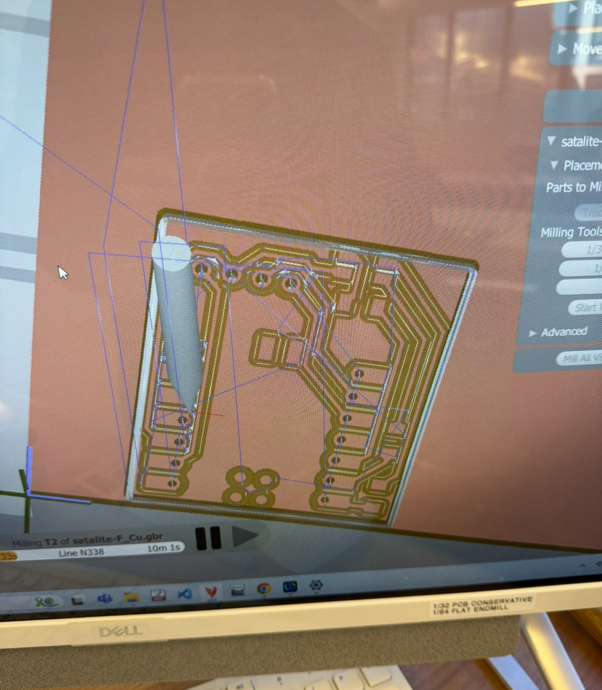
Then I uploaded the gerber files to Bantam software. Added the 1/64 bit, and then switched to the 1/32.
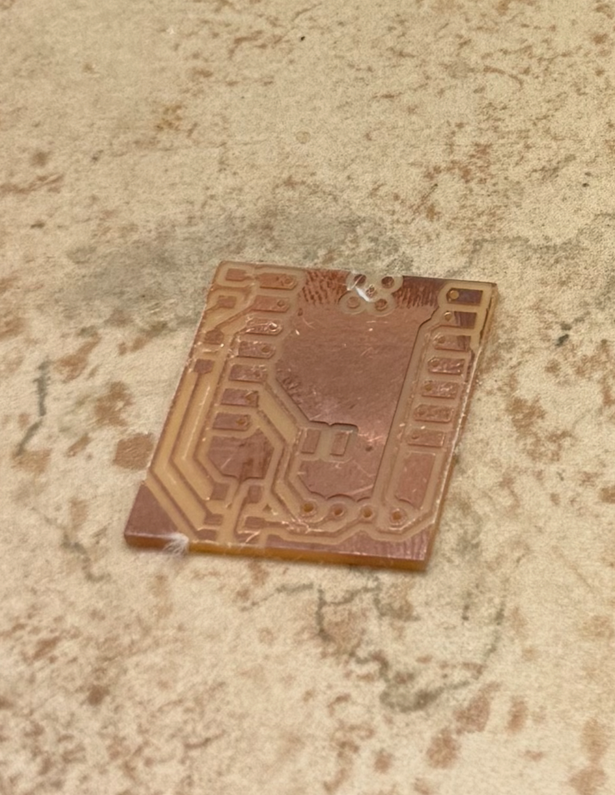
There is actually 2 issues with the PCB - that I only found out later.
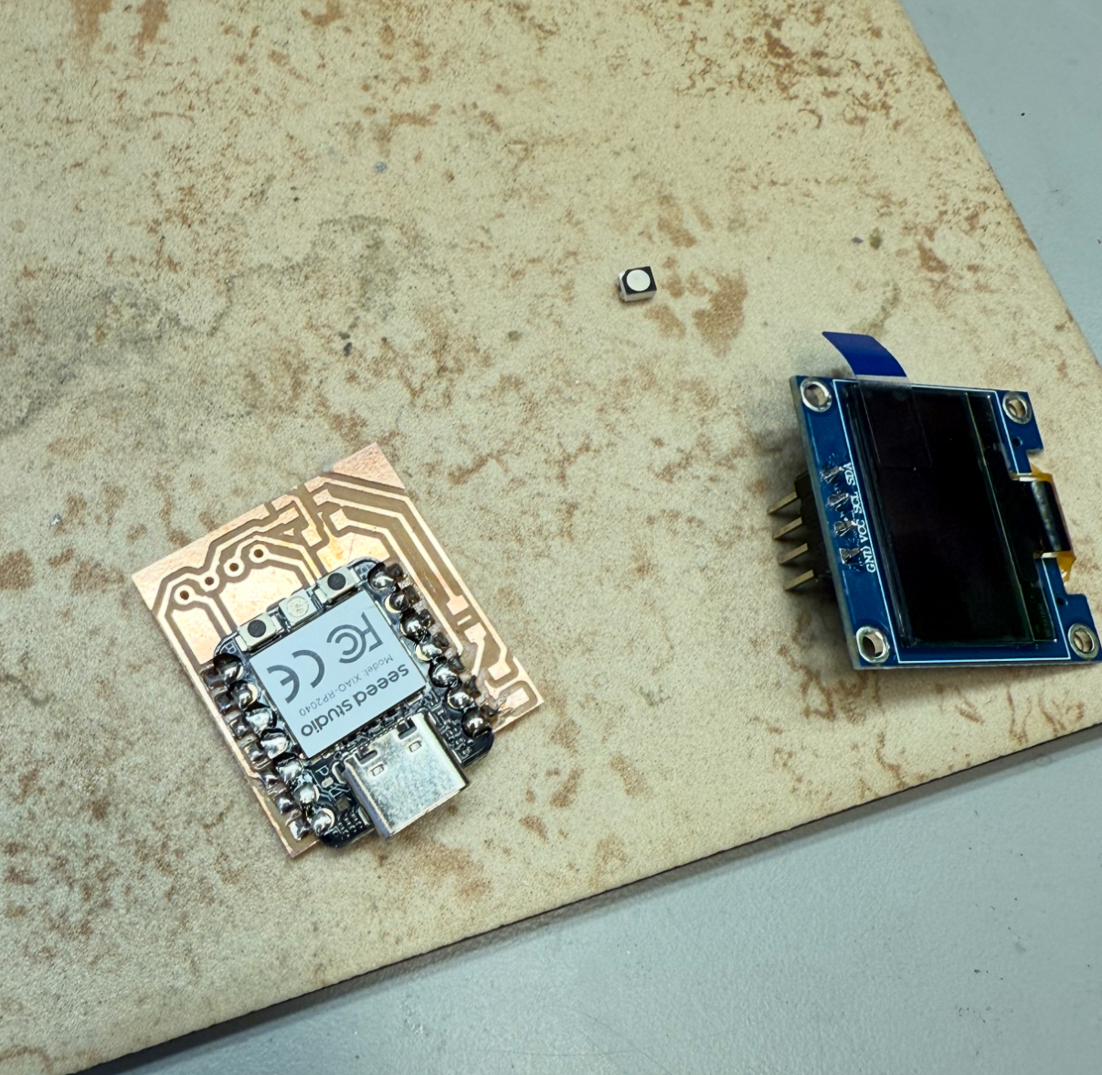
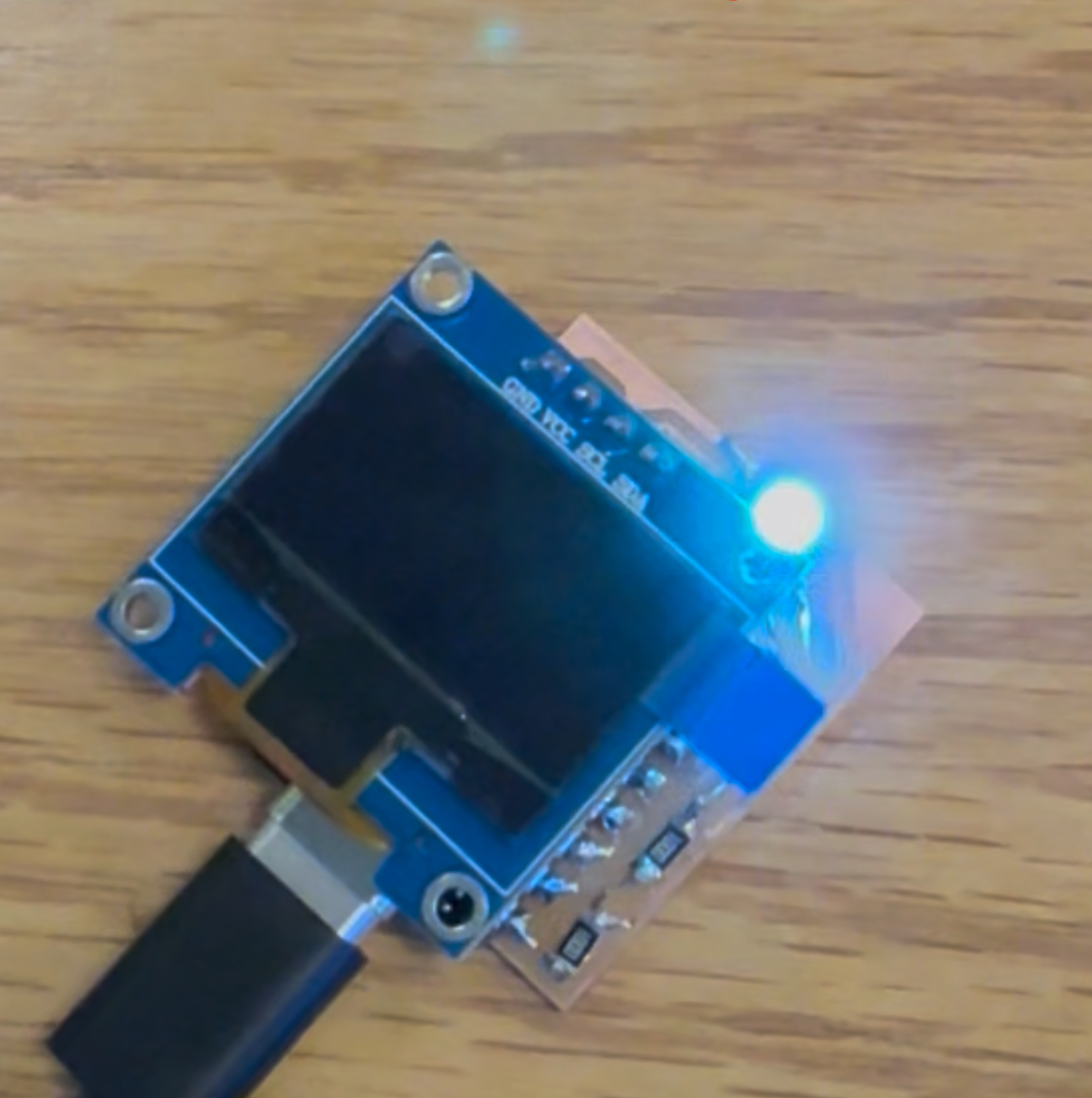
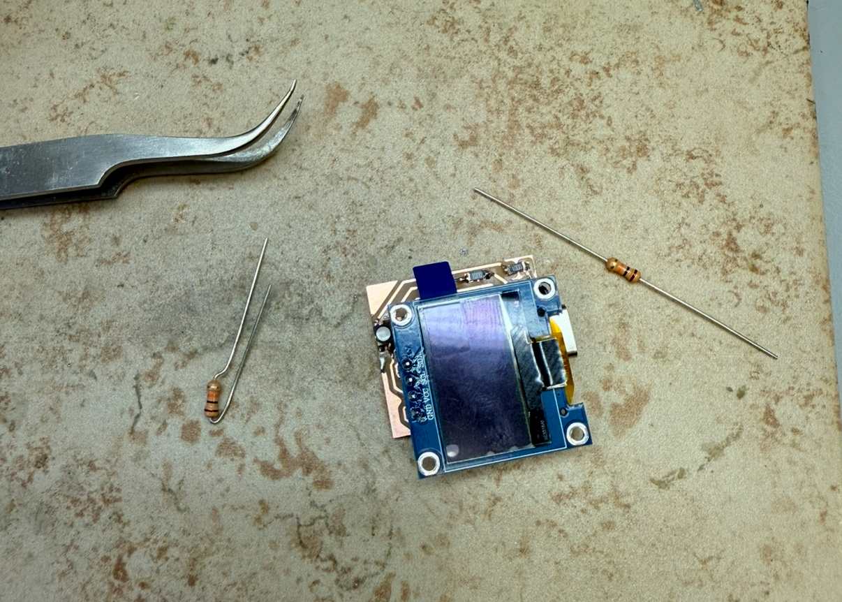
Soldering was not that bad, I just used the iron and no paste. Then I plugged it in and the LED turned on so I know that was connected. For some reason I couldn’t get the RED to look fully red - it was Pinkish. But the Green independently worked. But when I uploaded the example Adafruit sketch to use the screen it wasn’t working. Then Anthony helped me debug this and and turned out I was missing two pull up resisters. So with like 10 mins left in the open hours session, I did some fast soldering.
It looks kinda cool I guess.
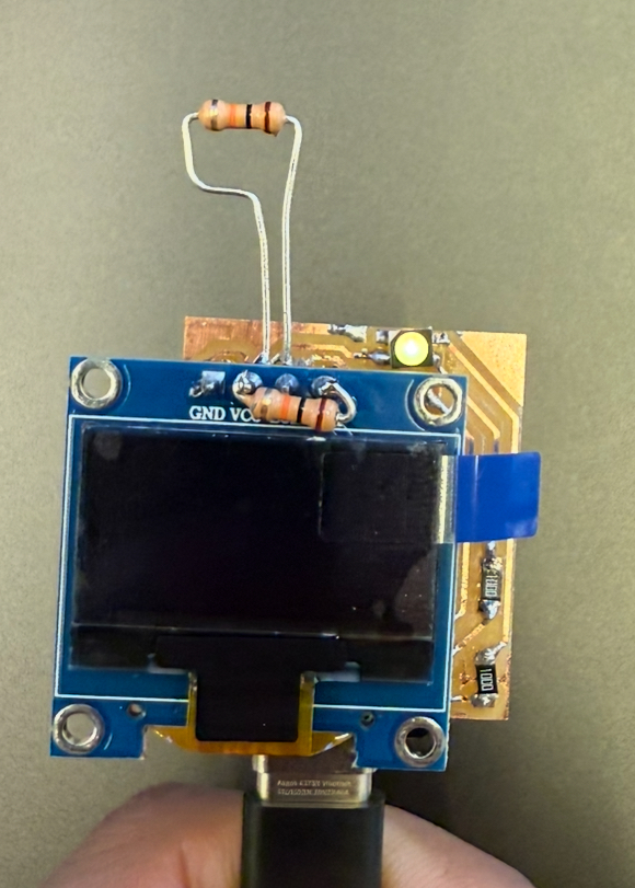
Then there was another issue, because it screen still didn’t turn on. Anthony found out that it was because I didn’t solder a pin properly to the xiao board. So then with like 5 mins less, I added a blob of solder but then that shorted the trace for the LED, so then I needed to use solder wick to remove that. I didn’t take any pictures of that since I was under a big time crunch. And finally it all worked.
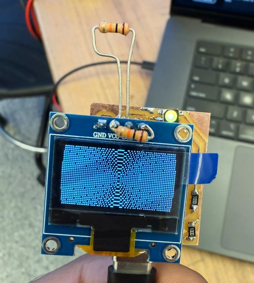
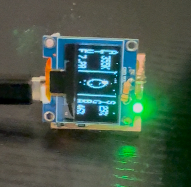
I ran a code ChatGPT made that makes it act like a small space station.
#include <SPI.h>
#include <Wire.h>
#include <Adafruit_GFX.h>
#include <Adafruit_SSD1306.h>

#define SCREEN_WIDTH 128
#define SCREEN_HEIGHT 32
#define OLED_RESET -1
#define SCREEN_ADDRESS 0x3C
Adafruit_SSD1306 display(SCREEN_WIDTH, SCREEN_HEIGHT, &Wire, OLED_RESET);

// RGB LED pins (active LOW)
#define RED_PIN   D0
#define GREEN_PIN D1
#define BLUE_PIN  D3

// Telemetry + state
float altitude = 352.4;
float velocity = 7.61;
float battery  = 91.7;
float signalStrength = 83.2;
float orbitAngle = 0.0;
unsigned long lastUpdate = 0;
unsigned long frameCount = 0;

// Helper: draw text vertically (each char stacked)
void drawVerticalText(int x, int y, const char* txt) {
  for (int i = 0; txt[i] != '\0'; i++) {
    display.setCursor(x, y + i * 6); // 6-pixel spacing
    display.write(txt[i]);
  }
}

void setup() {
  Serial.begin(9600);
  pinMode(RED_PIN, OUTPUT);
  pinMode(GREEN_PIN, OUTPUT);
  pinMode(BLUE_PIN, OUTPUT);

  if(!display.begin(SSD1306_SWITCHCAPVCC, SCREEN_ADDRESS)) {
    Serial.println(F("SSD1306 allocation failed"));
    for(;;);
  }

  display.clearDisplay();
  display.setTextSize(1);
  display.setTextColor(SSD1306_WHITE);
  display.setCursor(10, 10);
  display.println(F("SYSTEM BOOT"));
  display.display();
  delay(1500);
  display.clearDisplay();
}

void loop() {
  unsigned long now = millis();

  if (now - lastUpdate > 100) {  // update frame every 100 ms
    lastUpdate = now;
    updateTelemetry();
    drawVerticalConsole();
    flickerLED();
  }
}

void updateTelemetry() {
  altitude += random(-2, 3) * 0.1;
  velocity += random(-2, 3) * 0.01;
  battery  += random(-2, 2) * 0.1;
  signalStrength += random(-3, 3) * 0.1;
  orbitAngle += 0.06;
  if (orbitAngle > TWO_PI) orbitAngle -= TWO_PI;
  battery = constrain(battery, 0, 100);
  signalStrength = constrain(signalStrength, 0, 100);
  frameCount++;
}

void flickerLED() {
  // Soft airplane-style beacon: short dim flash with random interval
  static unsigned long lastBlink = 0;
  static bool ledOn = false;
  unsigned long now = millis();

  int interval = ledOn ? 50 : random(300, 700); // 50 ms on, 300–700 ms off

  if (now - lastBlink > interval) {
    lastBlink = now;
    ledOn = !ledOn;
    if (ledOn) {
      // Choose faint color depending on orbit phase
      int phase = ((int)(orbitAngle * 100)) % 360;
      int base = 40; // dim brightness
      if (phase < 120)       setColor(base, 0, 0);   // red
      else if (phase < 240)  setColor(0, base, 0);   // green
      else                   setColor(0, 0, base);   // blue
    } else {
      setColor(0, 0, 0);
    }
  }
}

void setColor(int r, int g, int b) {
  analogWrite(RED_PIN, 255 - r);
  analogWrite(GREEN_PIN, 255 - g);
  analogWrite(BLUE_PIN, 255 - b);
}

void drawVerticalConsole() {
  display.clearDisplay();

  // Vertical dividers
  display.drawLine(40, 0, 40, 31, SSD1306_WHITE);
  display.drawLine(84, 0, 84, 31, SSD1306_WHITE);

  display.setTextSize(1);
  display.setTextColor(SSD1306_WHITE);

  // --- Left column: vertical telemetry ---
  drawVerticalText(2, 0, "ALT");
  display.setCursor(12, 6);
  display.print((int)altitude);
  display.println("K");

  drawVerticalText(2, 20, "VEL");
  display.setCursor(12, 26);
  display.print(velocity, 2);

  // --- Center: orbit & vertical “data matrix” ---
  int cx = 62;
  int cy = 16;
  int r = 7;
  display.drawCircle(cx, cy, r, SSD1306_WHITE);
  int sx = cx + r * cos(orbitAngle);
  int sy = cy + r * sin(orbitAngle);
  display.fillCircle(sx, sy, 2, SSD1306_WHITE);

  // Data stream: falling bits
  for (int i = 0; i < 4; i++) {
    int streamX = 55 + i * 3;
    int y = (frameCount * (i + 1) * 3) % SCREEN_HEIGHT;
    display.drawPixel(streamX, y, SSD1306_WHITE);
    display.drawPixel(streamX, (y + 6) % SCREEN_HEIGHT, SSD1306_WHITE);
  }

  // --- Right column: COMMS vertically ---
  drawVerticalText(94, 0, "SIG");
  display.setCursor(104, 6);
  display.print((int)signalStrength);
  display.println("%");

  drawVerticalText(94, 20, "BAT");
  display.setCursor(104, 26);
  display.print((int)battery);
  display.println("%");

  // --- Flickering checksum / matrix noise at top ---
  for (int i = 0; i < 15; i++) {
    int x = random(0, SCREEN_WIDTH);
    int y = random(0, 2);
    if (random(0, 6) > 3) display.drawPixel(x, y, SSD1306_WHITE);
  }

  display.display();
}
Files: