Computer Controlled Cutting
Acknowledgments
Anthony and Dave helped me use the CNC machine and also find the right screws. Anthony also helped me tweak my model and set up the CAM in Fusion.
Group Assignment
With Anthony we first went over the design - we were going to cut a square with tabs of different sizes to test out which one would fit the best. We found that when the hole and tab are of the same size - the fit is pretty good which is what I used for my project.
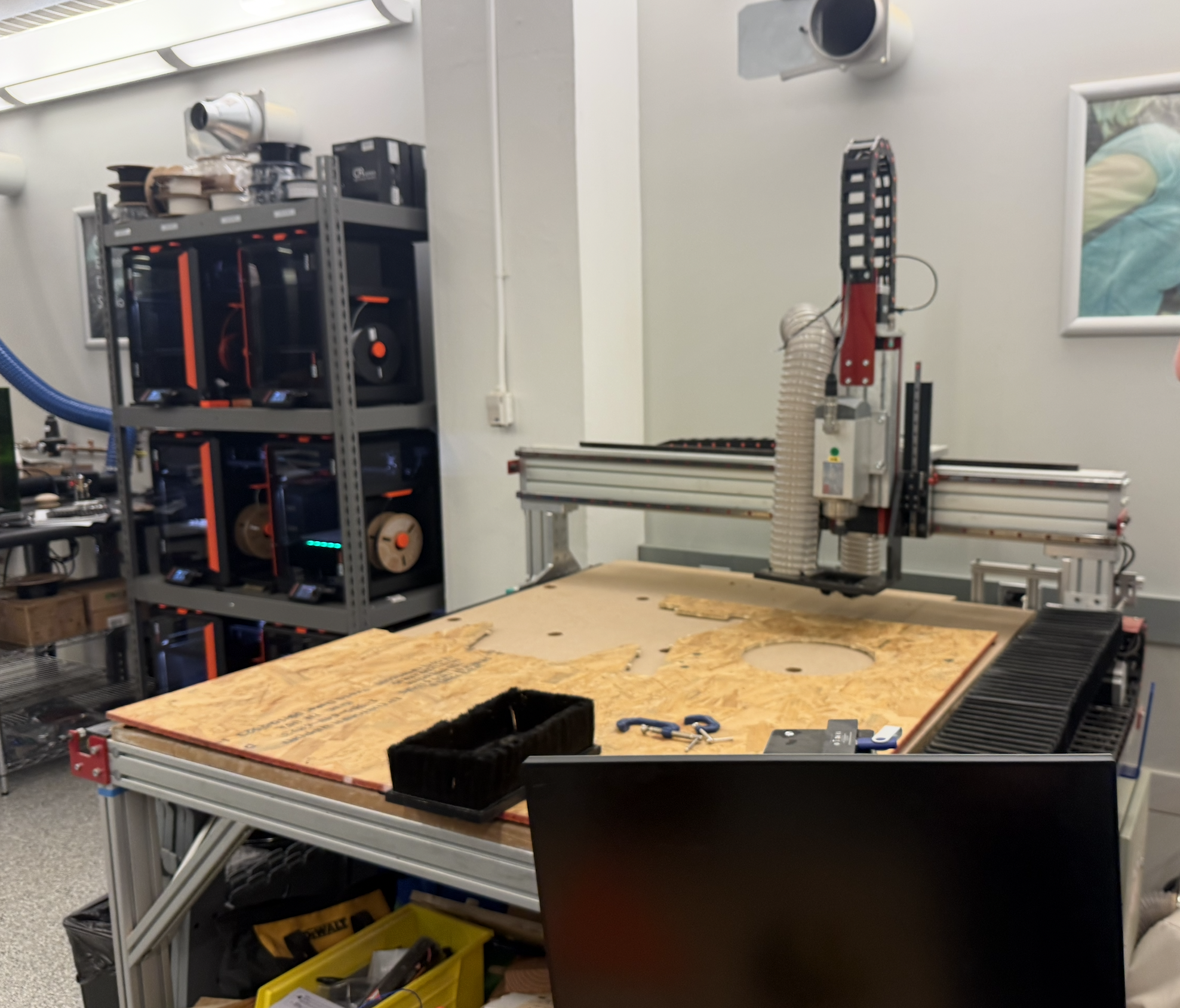
We then did safety training on using the CNC machine, learning about the estop, software, and how to use the plastic nails and the nail gun to hold our OSB. We are using the AVID 4x4 CNC.
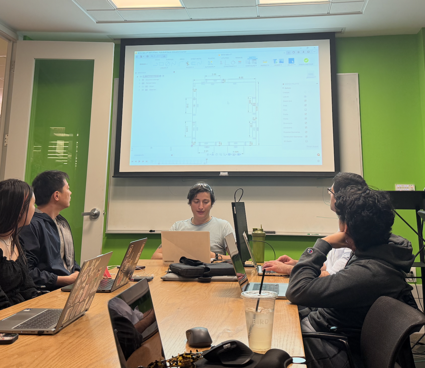
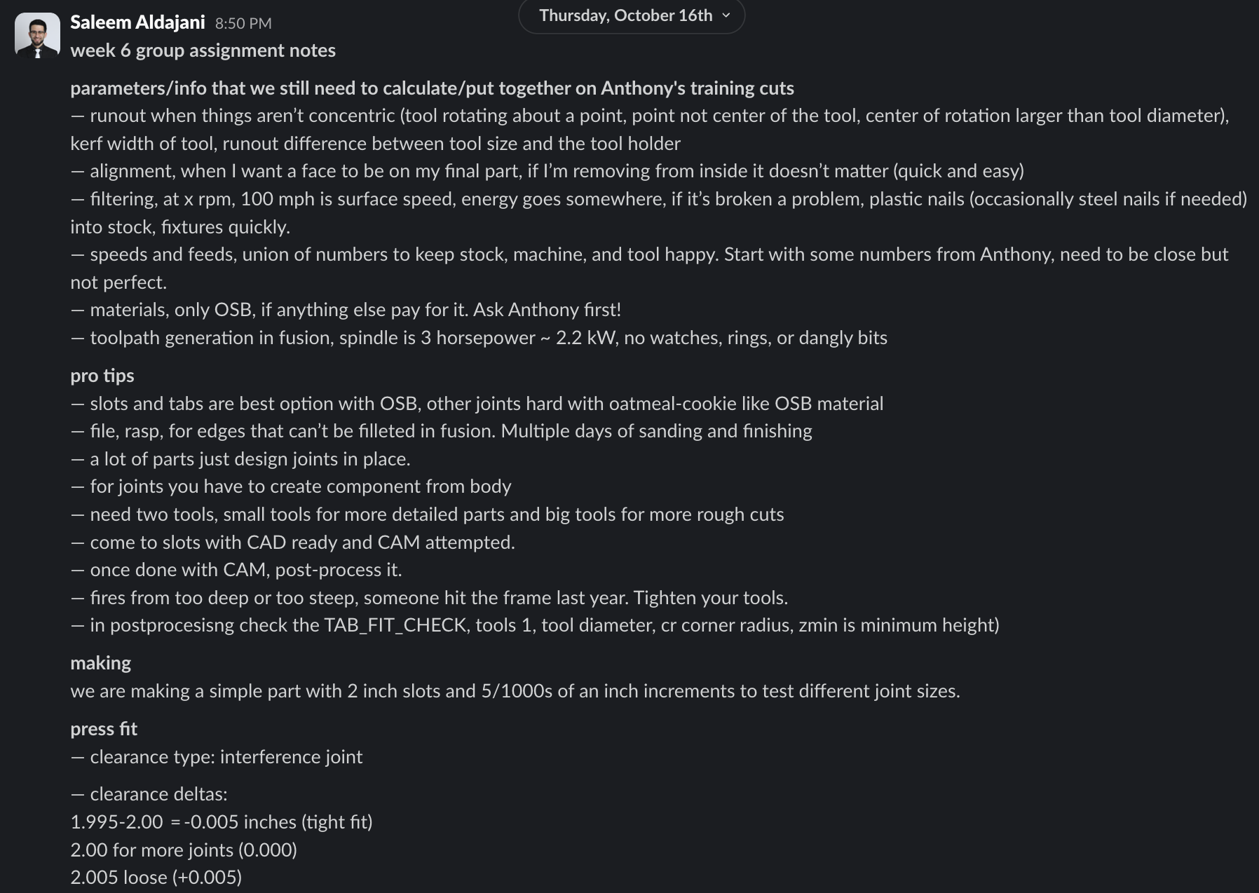
Saleem was kind enough to share the notes from our session.
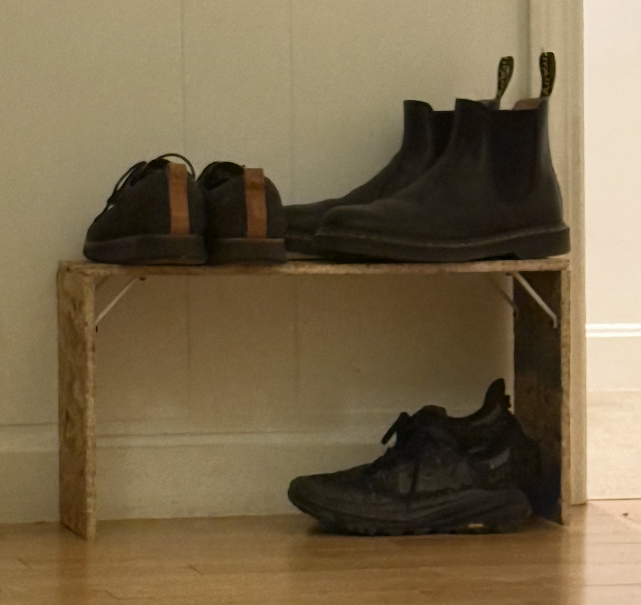
Now, for this project I wanted to make a shoe-rack. It is something that I have been meaning to buy for my apartment but Muji never seems to have them in stock so it has been delayed. So I thought this week would be a perfect opportunity. Initially I spent some time designing the CAD models in Onshape, and ended up with this.
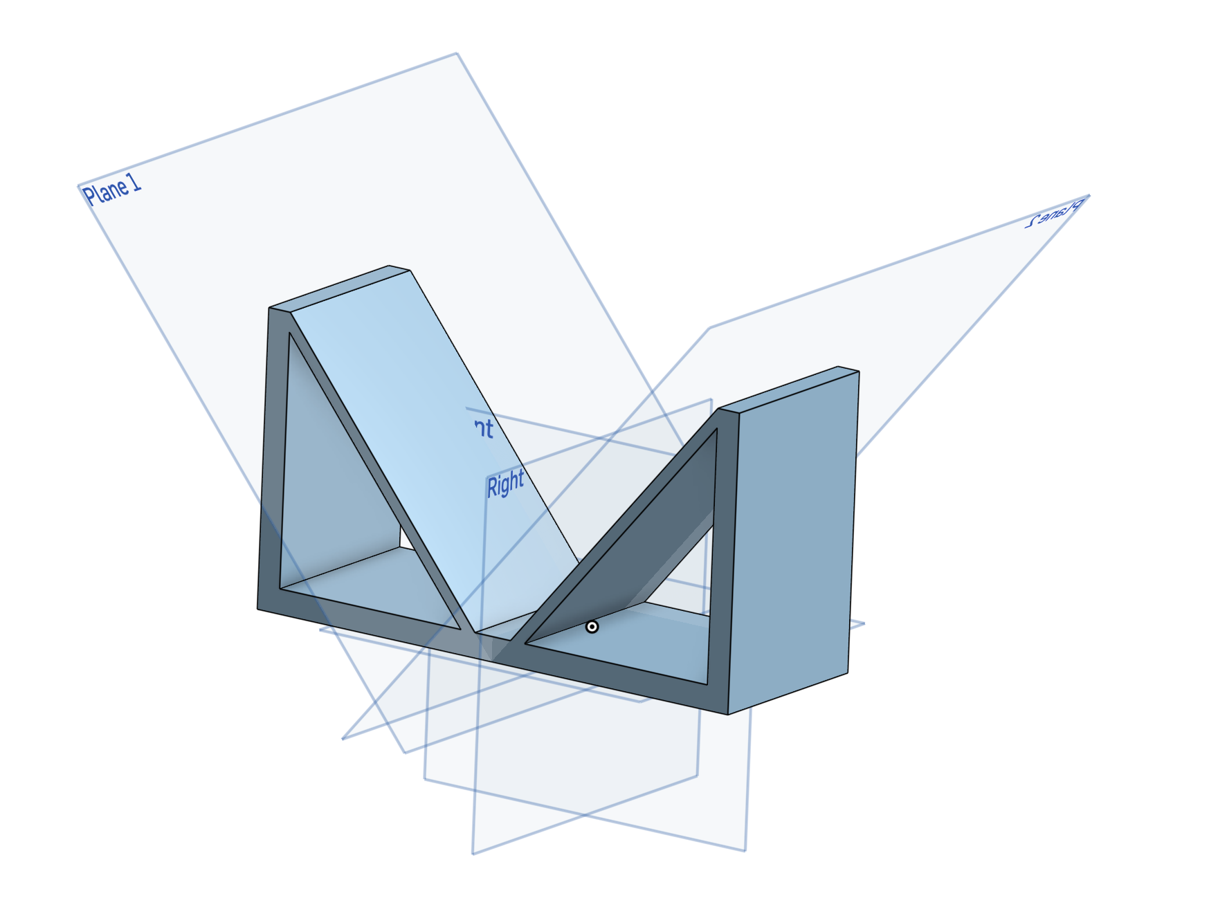
However, I then I tried to splice it to generate the joints and it turns out this is not the right way to go. So then I started redoing it where I design each part separately.
I happened learn through Anthony during our Group assignment and then learned that we need to use Fusion for CAM, so then I scrapped everything up and downloaded Fusion. I designed a simpler version first as part of Spiral Development, where the joints are 4cm long.
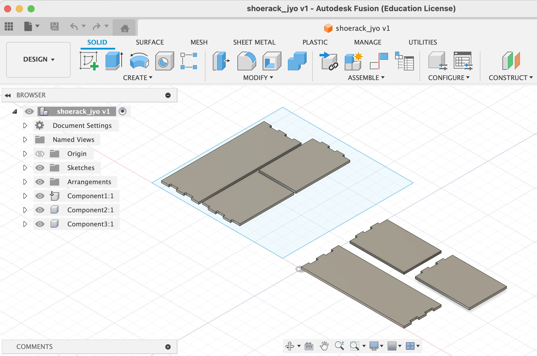
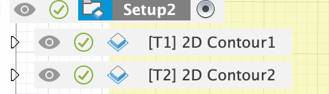
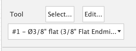
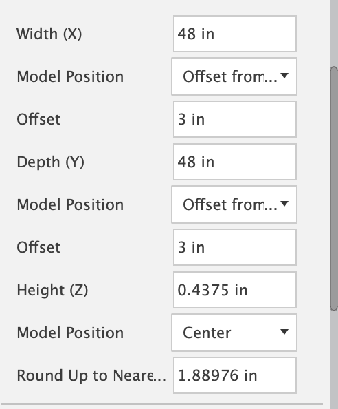
Then following Anthony’s video: https://vimeo.com/1127704858?share=copy&fl=sv&fe=ci and Anthony’s direct help I then turned my design into a GCODE file. I also used the DogBone tool here: https://ekinssolutions.com/product/nifty-dogbones-f360/.This required us to assemble the parts, arrange them, set the orientation (x,y,z) axis, add the tabs, choose the 2 tools.
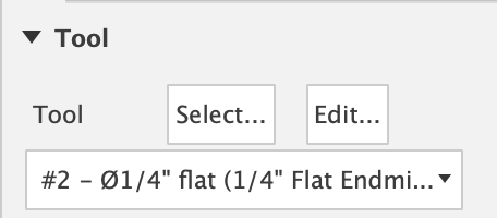
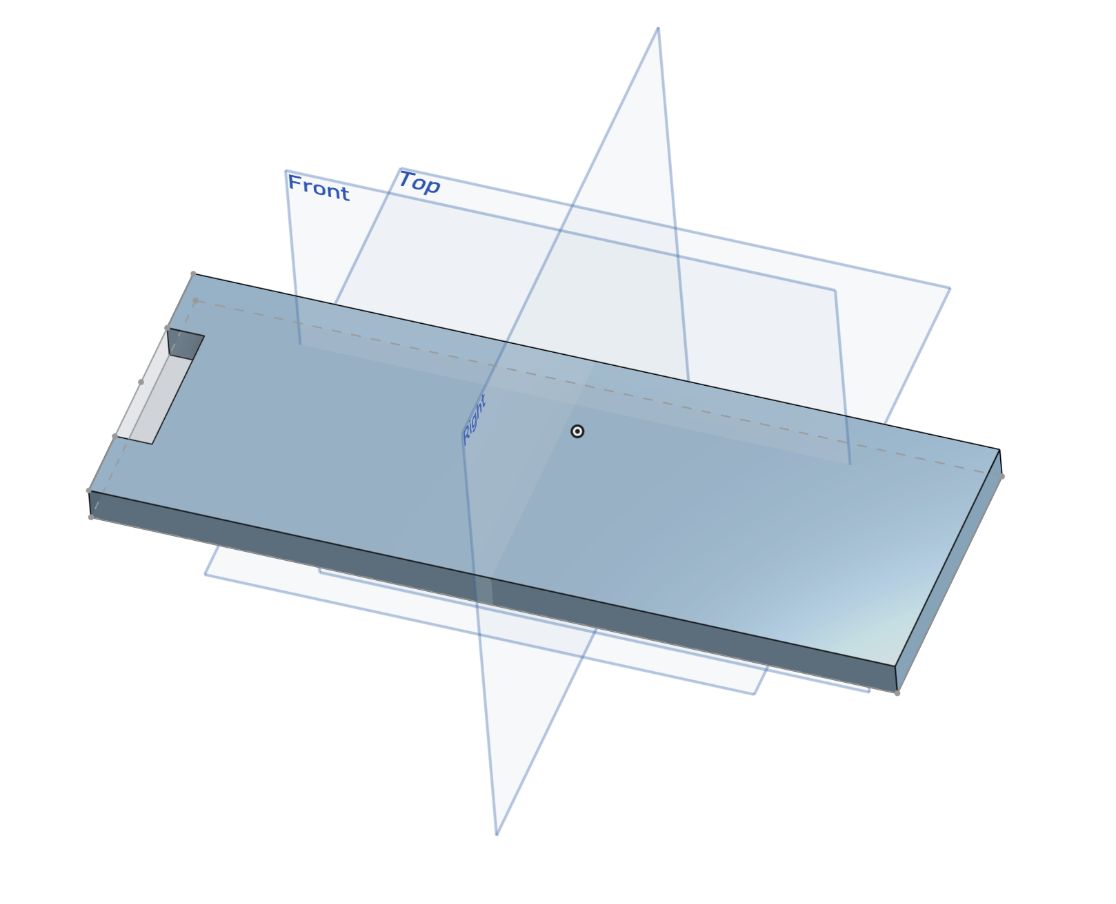
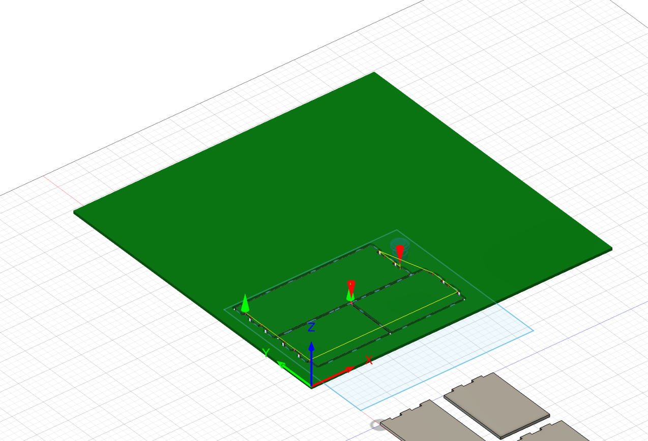
The values are the same ones used in the video except for a different model positions.
Resulting in this.
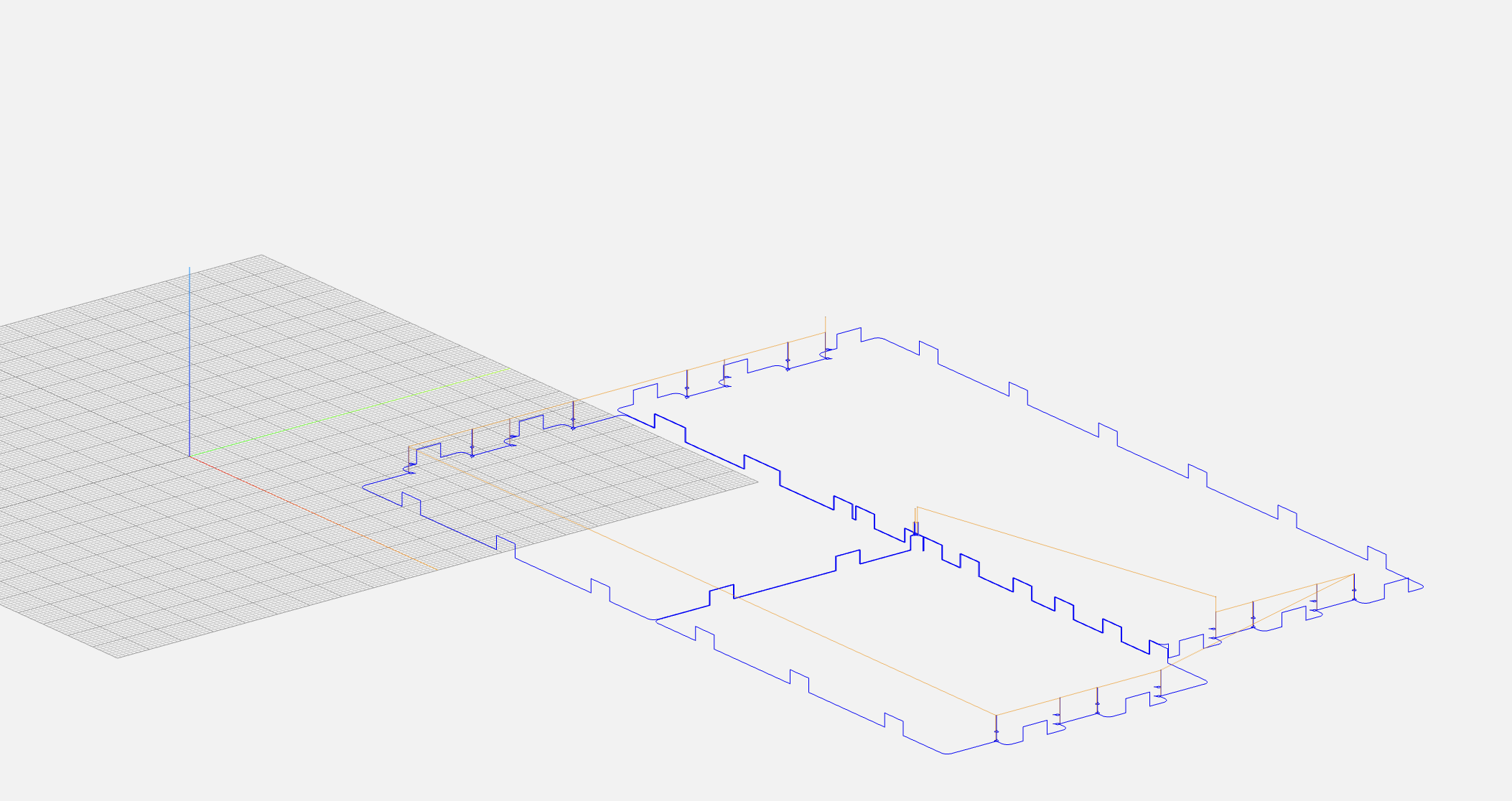
From here we can generate the GCODE. For curiosity I used https://ncviewer.com/ to visualize the GCODE. What is nice to see here is the vertical bumps that represent the tabs.
Then Anthony and I loaded the GCODE into the AVID and we did the homing in x,y,a, and tool change in the middle of the job. Finally obtaining this.
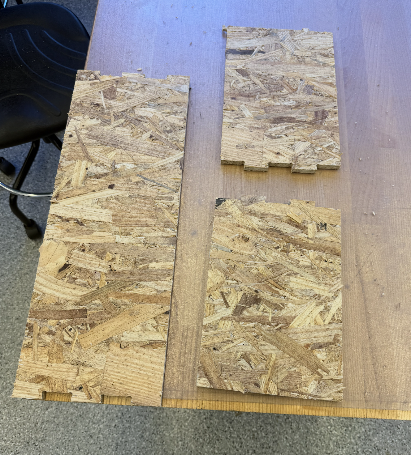
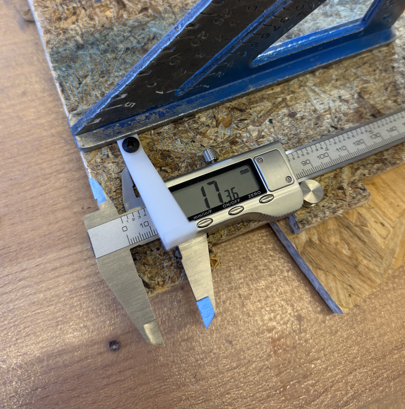
The joints worked well, I used a hammer to get them in. But obviously, this structure isn’t stable, as we learned in class about Maxwell’s constraints. So I thought I would use my 3D printing knowledge to improve this. I designed a simple support to hold both piece of wood stiff at 90 degrees.
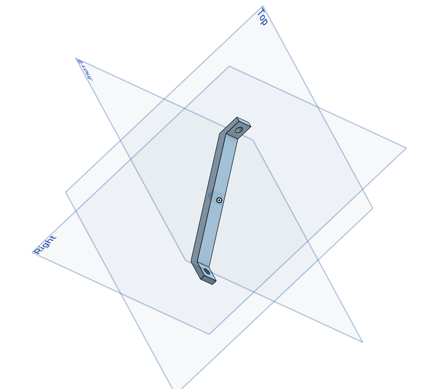
Then on the Prusa ONE Core, I printed 4 of them.
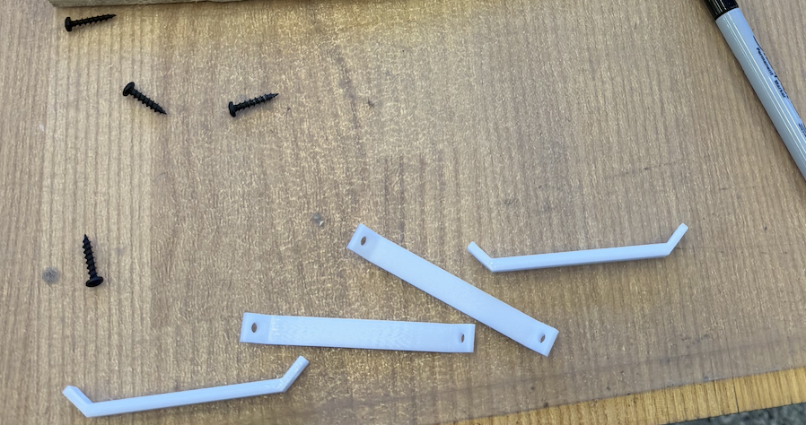
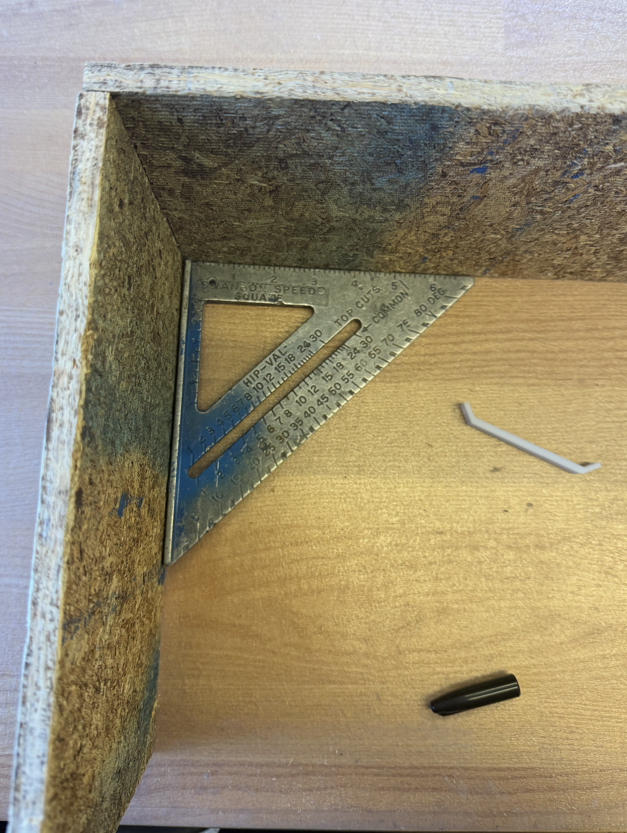
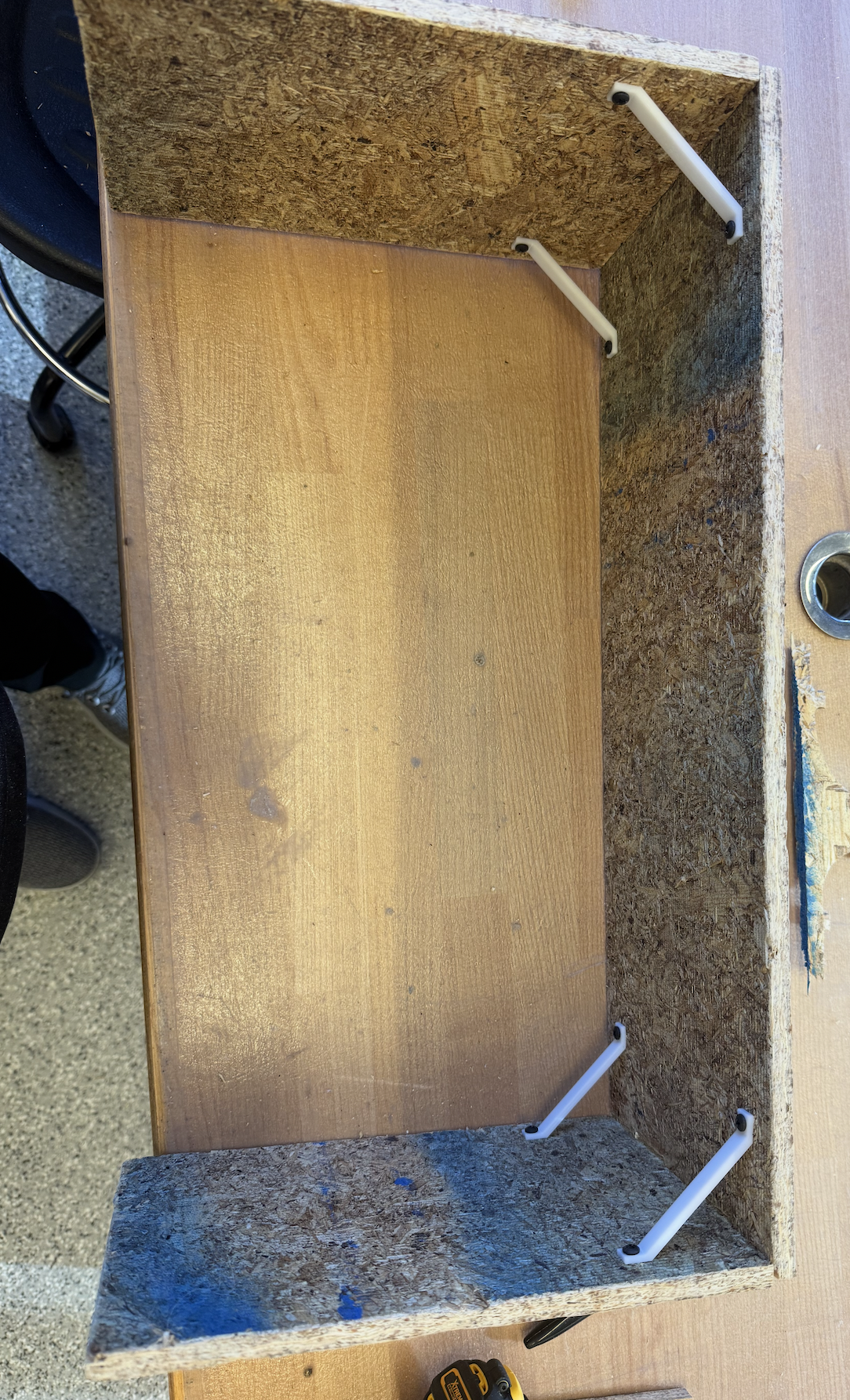
Then it was time to assemble everything. I used the 90 degree tool to make sure the woods were aligned properly and then used the sharpie to draw dots on where the screw into.
Files: