Input and Output Devices
Group Assignment
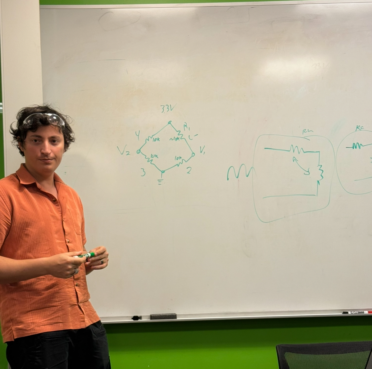
With Saleem and Anthony we did the group assignment together.
Saleem had a load sensor that we used like this: https://www.amazon.com/Digital-Weighing-Arduino-Portable-Electronic/dp/B09K7G3477/ref=sr_1_5?crid=1GTWZOE1FQZP0&dib=eyJ2IjoiMSJ9.KRhJgNLgchVydlJJ6igVpa3989SxrRtPJBWidCej3dNSBn_-m_TEgGrxi7V2FXKUUvlPwBldjR01AvI8zmwawtFxzQ32qbs6Vic069lq3f4alrC4qH59bvBXK8euW-9wfYJJewq8jvuta2MG7a50CdyrWgJNJw24PZ0lqfAnFa2DTComYgaznToJ_qot6vgNudvfSG0DfEcPsZO0MjVJA9EKeglS5OrFE22LUmCQCdw.onTeJUkvYO5jwOhVpyPV3jKSLok-7L_W4cCNc9DArSY&dib_tag=se&keywords=load%2Bsensor&qid=1761702767&sprefix=load%2Bsenso%2Caps%2C144&sr=8-5&th=1, then Anthony explain how it works and what are the 4 wires doing. He said the change in voltage will be very small - too small for our microcontrollers to read so that’s why we need some form of an amplifier. The following is a Wheatstone Bridge.
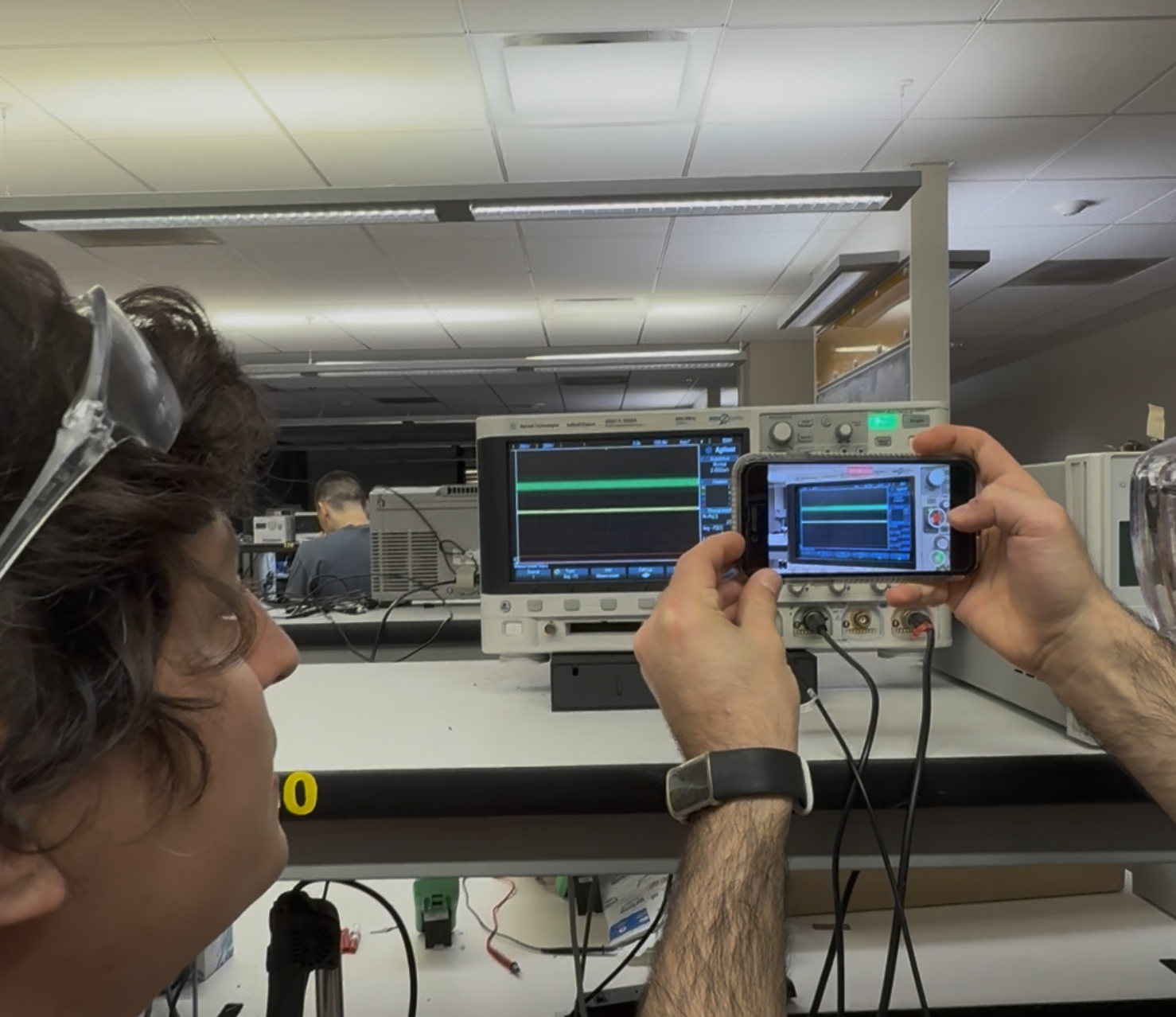
Then with the channels connected to SCK and DT, we were able to notice a tiny change when pressing the load cell - this was the analog reading.
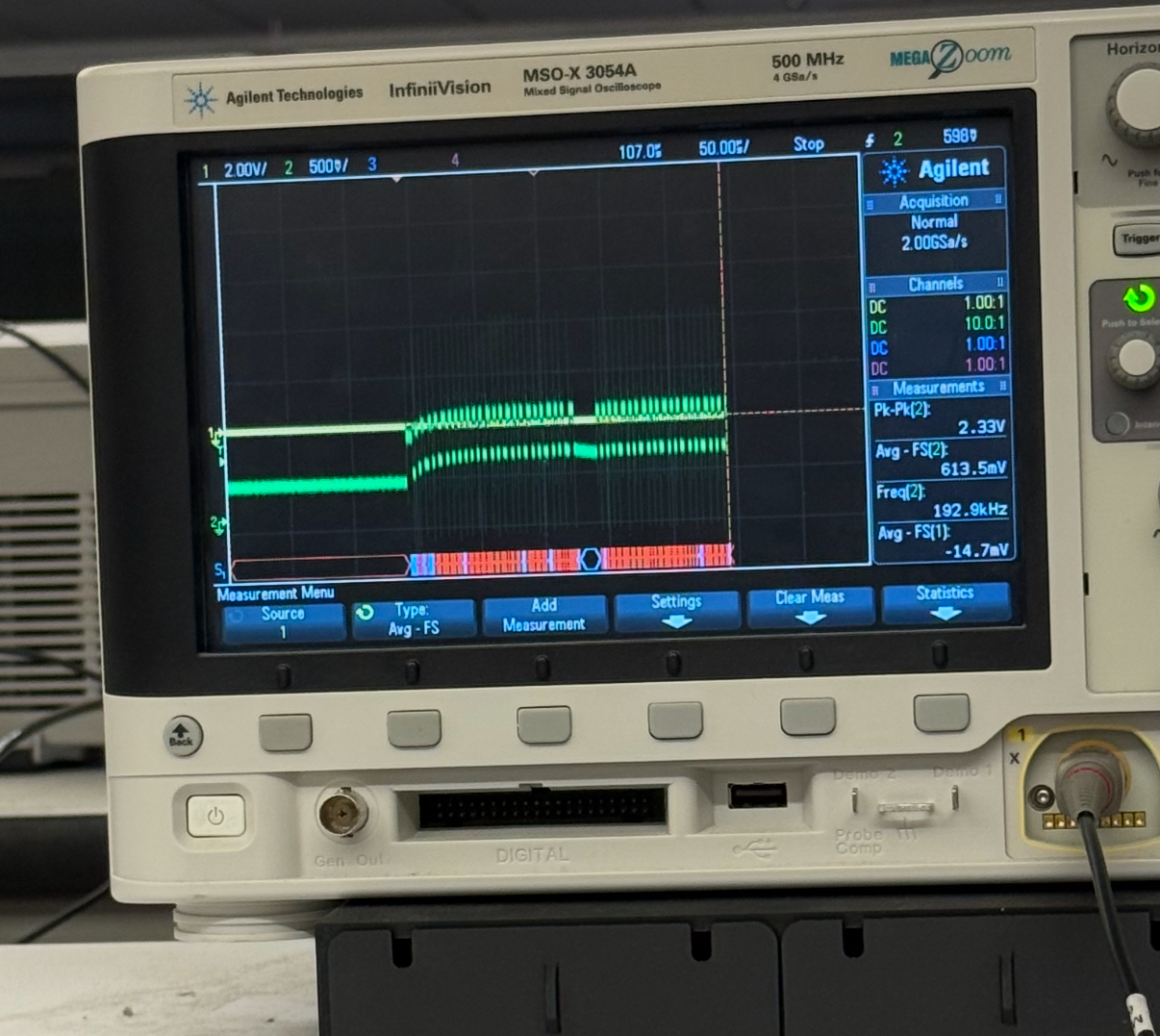
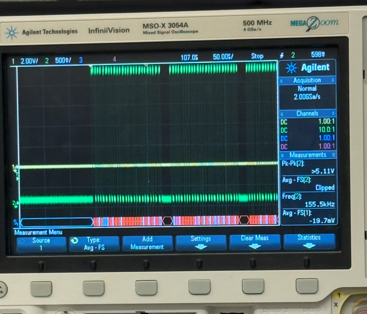
For the digital reading, we obtained the following for the clock and data (left and right respectively).
For this week I wanted to combine the input devices and output devices. I wanted to take inspiration from https://learn.adafruit.com/piccolo/overview, which visualizes the sound.
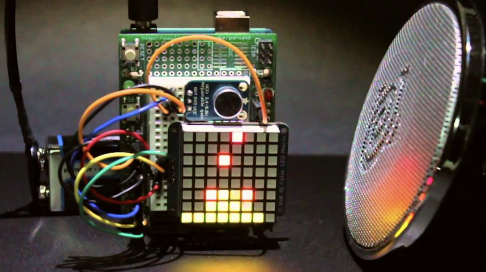
I ended up deciding to have light be the entity I sense, via a photo transistor and have a bar of leds indicate the light level.
First I needed to look at how to use a phototransistor. I have had experiences with a photo resister before, so after checking: https://deepbluembedded.com/arduino-phototransistor-circuit-code-example/, it seems similar to use. However, I had a question, and it was one I have had since the electronics production assignment, what is the role of the resistor.
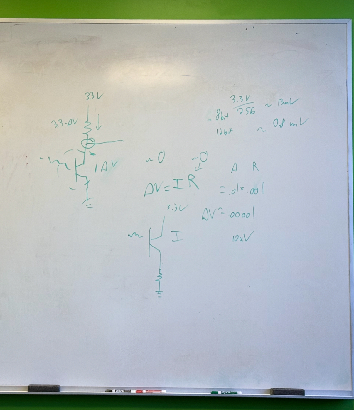
I went to office hours and asked Anthony and got a nice mini lecture on the reason. Which is the photo transistor is going to change the current based on the light level. However, our micro controller (RP2040 in our case) can only measure the voltage in the analog input pins. Therefore we need a way to take (change in current to change in voltage). Through the equation , since we know based on the resistor we can then figure out . I did not know this before and it is very interesting.
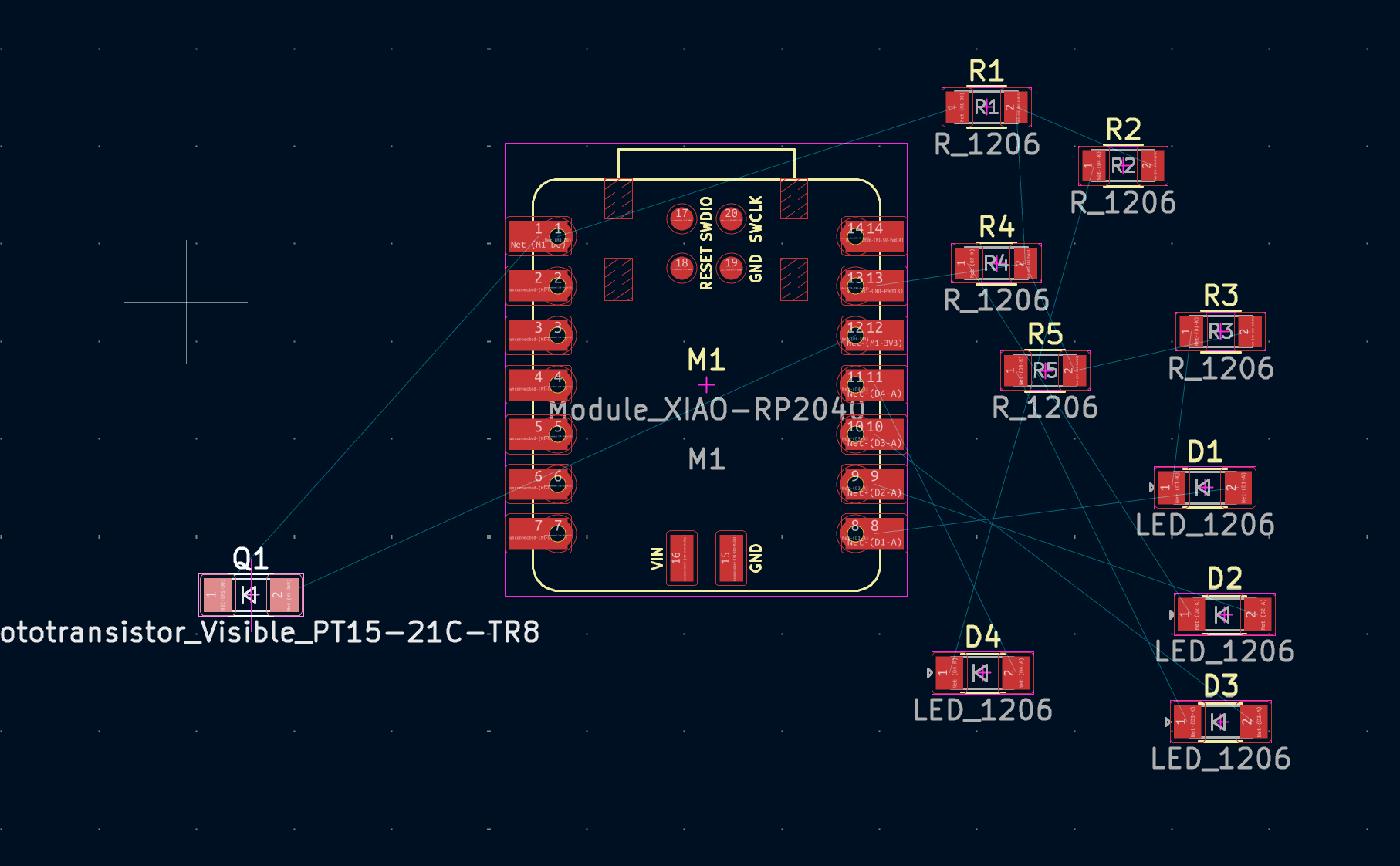
Based on this and looking at the pinout of the XIAO RP2040, I got to designing the schematic in KiCad.
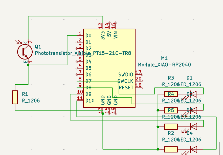
The resistor are 1k Ohm 1206 form factor - from our inventory. I picked orange Leds in the same 1206 form factor. When I asked Anthony for a phototransistor, he asked me if I wanted a visible one or IR one, I went with the visible option.
Parts:
https://www.digikey.com/en/products/detail/seeed-technology-co-ltd/102010428/14672129
https://www.digikey.com/en/products/detail/everlight-electronics-co-ltd/PT15-21C-TR8/2675871
https://www.digikey.com/en/products/detail/dialight/5988230107F/1291283
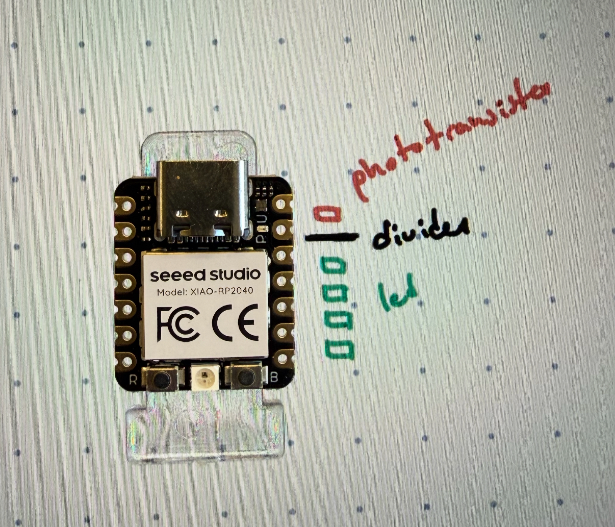
Then I wanted to practice good routing. So I took some time to figure out where I want the parts. I used my IPad to draw out the rough positions of the photo transistor and the leds. I initially also thought of adding a physical divider to prevent the leds lights from interfering too much with the phototransistor but that ended up not being much of a problem and wasn’t needed at the end.
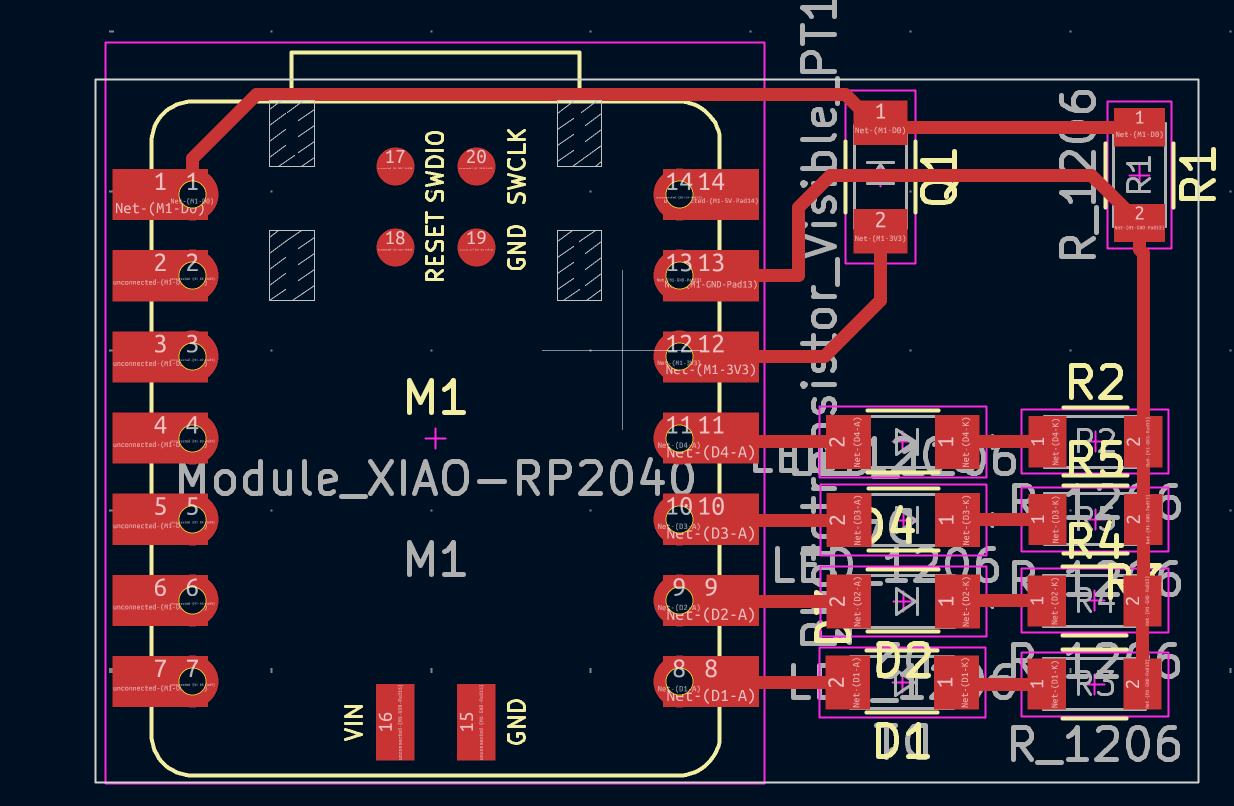
As you can see the routing is clean (to my standard at least), and Anthony make the corners less sharp by rounding them. He said this is better when soldering. The minimum clearance is 0.4 mm and the minimum track width is also 0.4 mm.
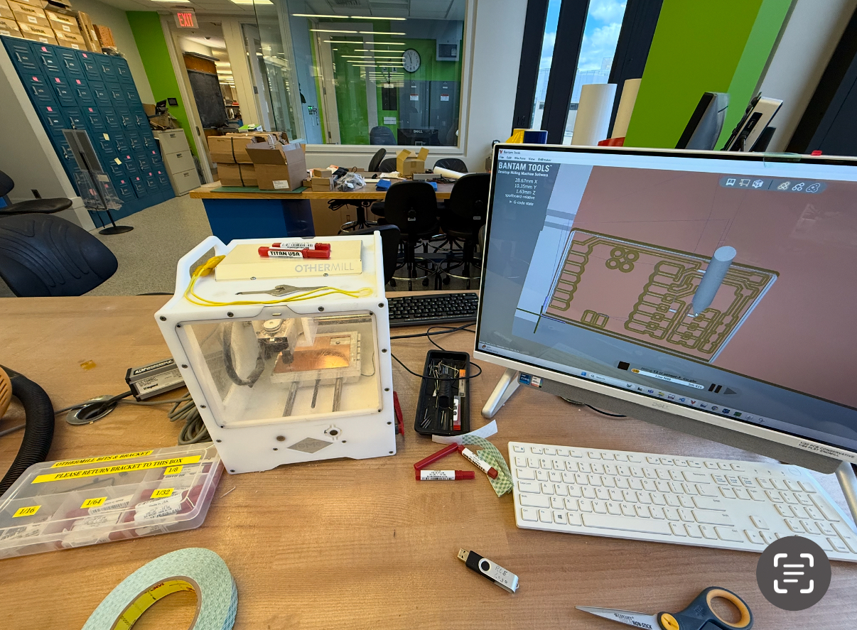
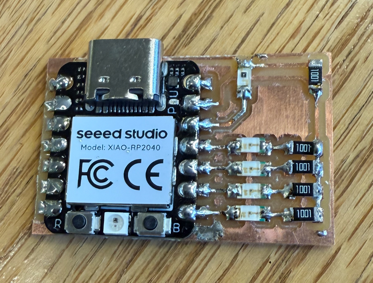
Then I sent the front design and the edge cuts to the Bantam PCB milling machine and following the same procedure for our PCB design we started with the 1/64 mill and then the 1/32.
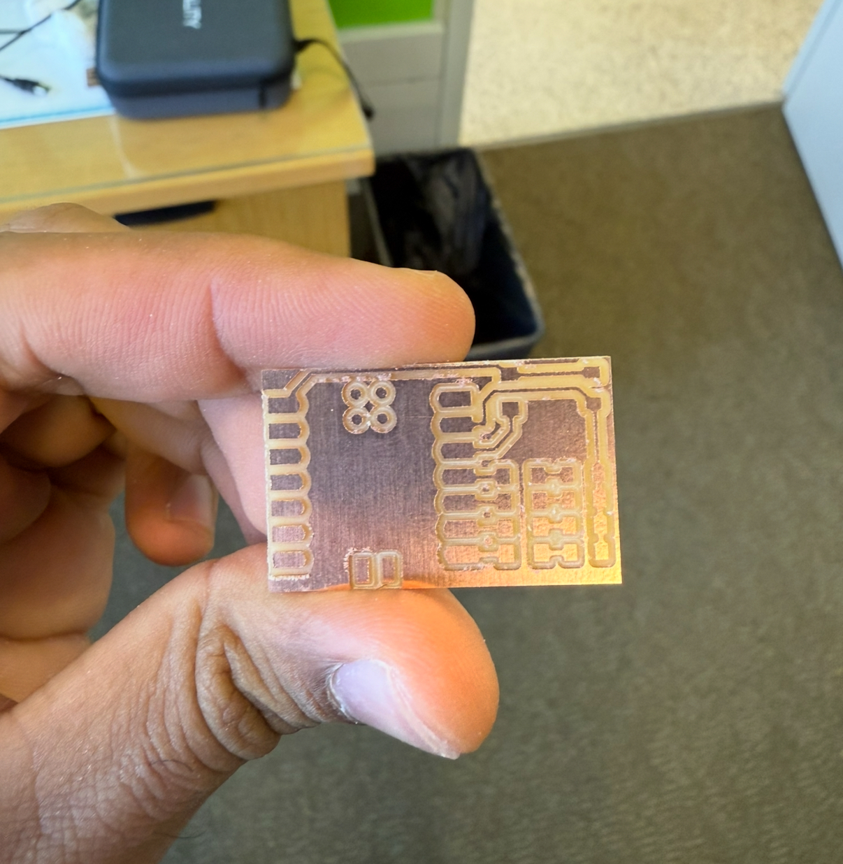
It was a quick job and there were no hiccups, and soldering it was straight forward as well. I have been using the method of heating the pad and the part first for few seconds and that helps a lot.
Then I worked with ChatGPT to make sure each component works, and it did. We plotted the phototransistors analog read value to the serial monitor - the range was between 2 and 10 ish when I shined by phone’s flashlight on it. Based on this, we then accordingly calibrated the thresholds for the led bar.
The ChatGPT conversation is here: https://chatgpt.com/share/690033c8-b328-8007-a65b-03869d1f75fa
const int sensorPin = A0;             // Phototransistor on A0 (analog input)
const int ledPins[] = {1, 2, 4, 3};   // Physical LED order (swapped 3 and 4)

void setup() {
  Serial.begin(9600);
  for (int i = 0; i < 4; i++) {
    pinMode(ledPins[i], OUTPUT);
    digitalWrite(ledPins[i], LOW);
  }
}

void loop() {
  // Read light sensor
  int lightValue = analogRead(sensorPin);
  Serial.println(lightValue);  // For debugging: view range in Serial Monitor

  // Map 0–1023 to 0–4 LEDs
  int numLEDs = map(lightValue, 0, 10, 0, 4);
  numLEDs = constrain(numLEDs, 0, 4);

  // Light up LEDs accordingly
  for (int i = 0; i < 4; i++) {
    if (i < numLEDs) {
      digitalWrite(ledPins[i], HIGH);
    } else {
      digitalWrite(ledPins[i], LOW);
    }
  }

  delay(100);
}
And here is the working video!
Here are all the files to reproduce the work.