Assignment
Neil’s notes for this week’s lecture can be found here.
assignment
Design and produce something with a digital process (incorporating computer-aided design and manufacturing) not covered in another assignment, documenting the requirements that your assignment meets, and including everything necessary to reproduce it.
I document this below. I can’t think of anything that would help with my final project, so I’m setting a goal of making something with emotional value that I will keep for the rest of my life.
For this week’s assignment, I want to make a souvenir that will remind me of the time when I took the How To Make class at MIT. It’s not like I’d forget without it, but it’s nice to have a souvenir.
Training
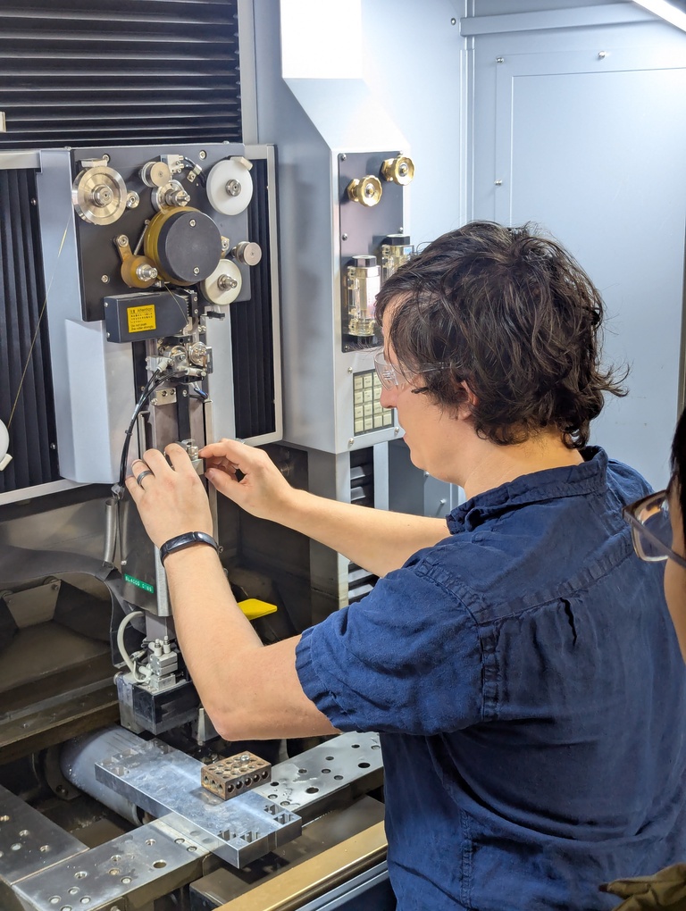
For the machine training, we’re meeting with Anthony who is kind enough to teach us how to use the machine. Thank you so much, Anthony. The TAs in this class are truly incredible and so generous with their time. I’m very grateful.
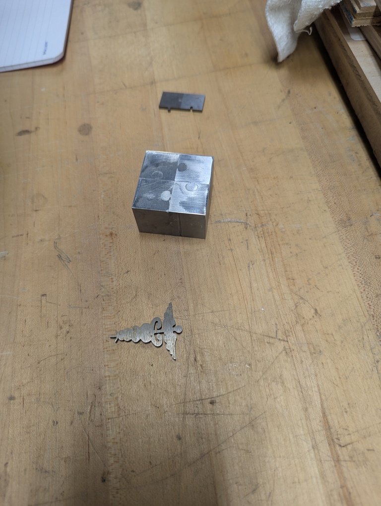
The process of using the machine is actually quite involved. The most important take-away: Don’t touch the live wire! You’ll do that only once. Anthony also brought some examples of what other people have made on the machine before. Puzzle pieces seem to be a classic example because they demonstrate the kind of tight fit that can be achieved with this machine.
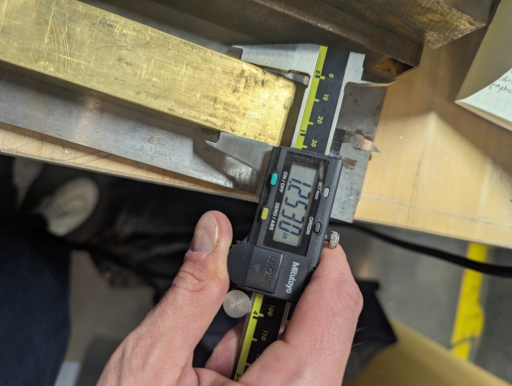
I’m also measuring the material that I would like to make my souvenir out of.
Design
I started by making a design in Figma.
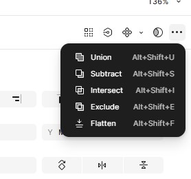
Using Figma’s boolean operators for paths, I’m using union and subtraction to create a shape that outlines the design as a whole.
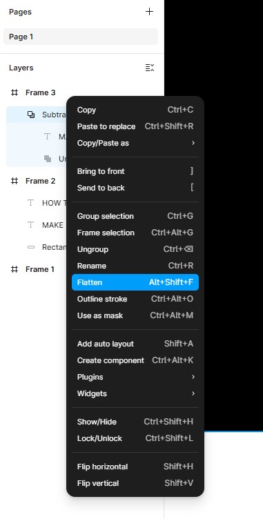
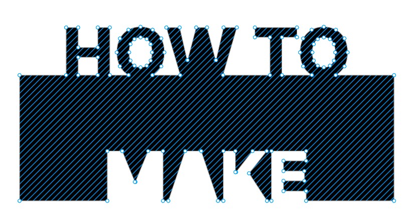
Flattening that shape results in a set of paths that I can easily edit. Since the wire EDM needs only a closed outline, I’m removing all the inner shapes.
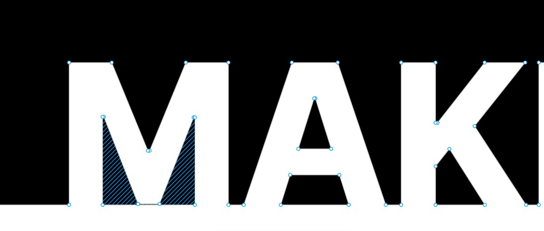
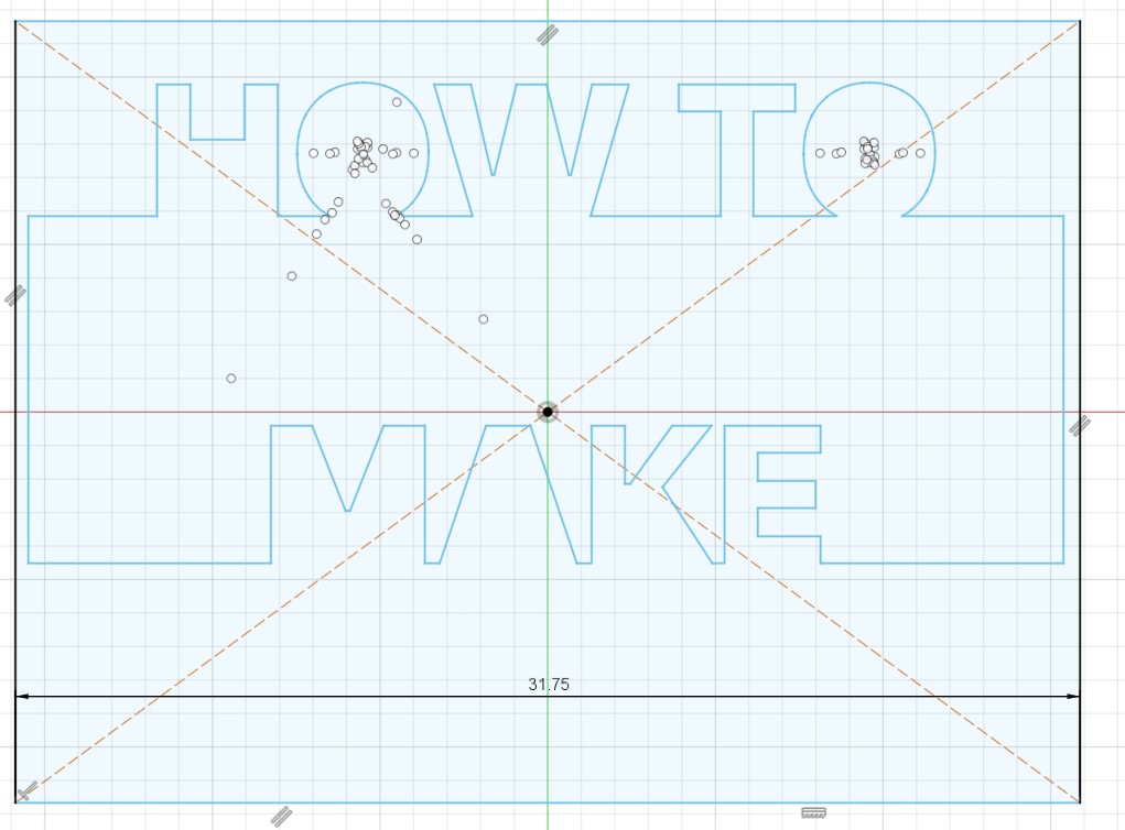
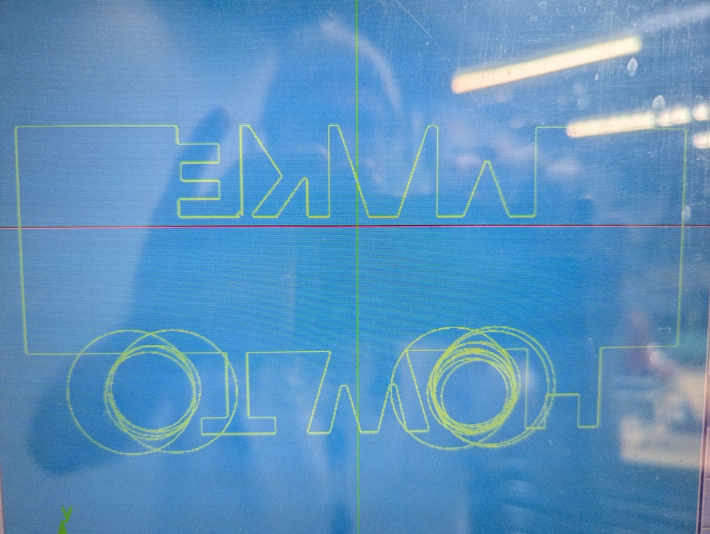
The image below shows what that looks like once all the shapes for the lower text (“MAKE”) are cleaned up. I proceed to do it for the shapes that the top, as well.
I then start playing with fillets. Anthony told us that the wire EDM struggles with acute corners. To be safe, I apply a corner radius everywhere. If you’re following along, don’t do this! Read about my struggles below.


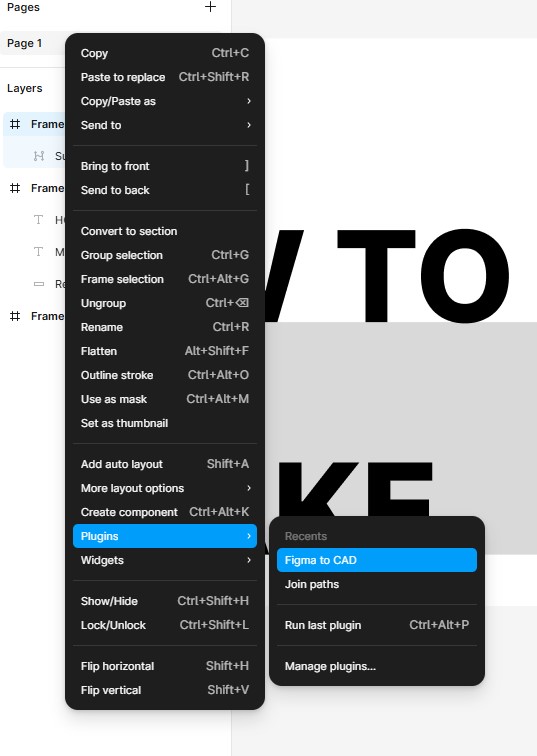
I use the “Figma to CAD” plugin to export the design to a DFX file. The result can be downloaded on the right.
Here’s where that process failed. The exported file doesn’t seem to corner radius baked into the path. Figma must be using that point property only for their rasterizer that turns paths into something that can be displayed on a screen. I’m not familiar with how Figma does that internally. It’s also possible that the DXF plugin just doesn’t export the corner radius correct, but my assumption is that it would if Figma were to represent the corner radius through a modified path internally.
Either way, I brought the DXF into Fusion because I wanted to make sure the dimensions are baked into the DXF correctly. That’s how I noticed that the corners aren’t round.
I use Fusion’s sketching tools to add a box with the dimensions of the piece of metal that I want to cut the shape out of. That allows me to scale the design such that it fits. I use the Modify -> Sketch Scale feature in the sketch environment for this.
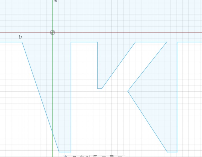
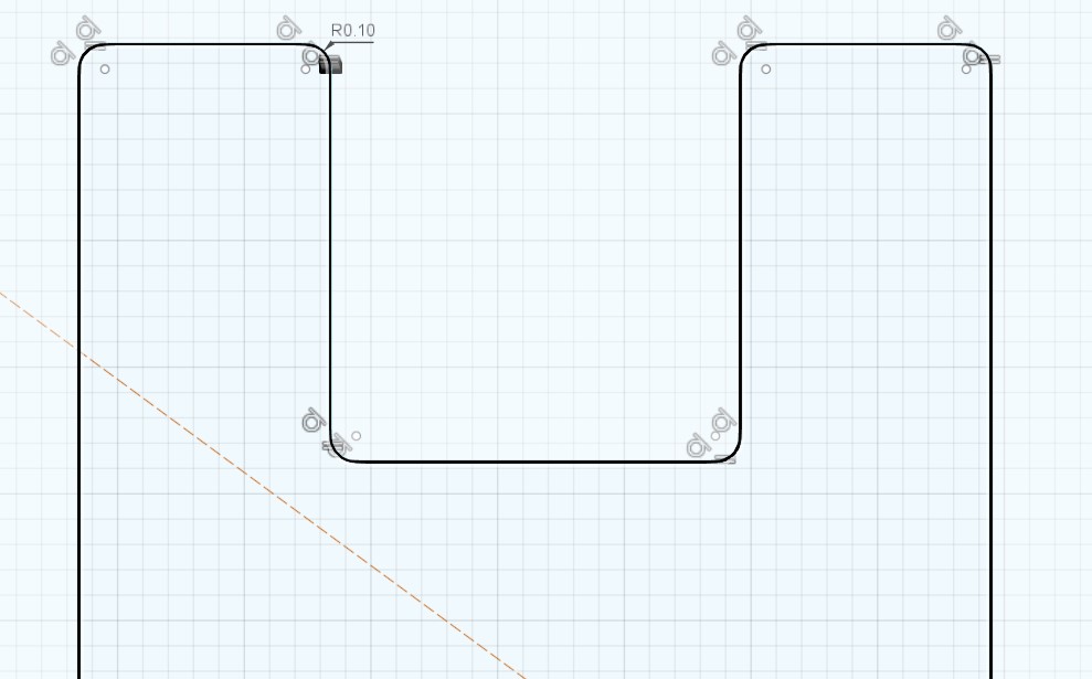
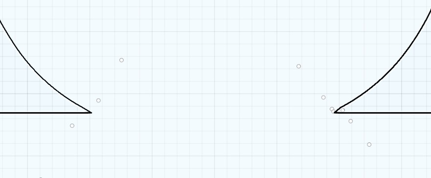
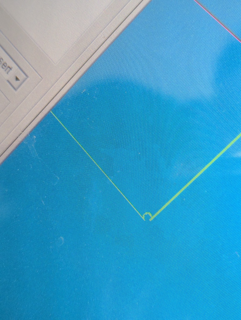
Some corners are very easy to equip with a fillet. Anything that’s a 90 degree angle in my design just consists of 2 lines that meet in a point. Adding a fillet to that point does the trick. I do that everywhere in the design. Example:
Acute corners and round lines are trickier. The round lines consists of multiple linear segments. That makes it impossible to create fillets of larger sizes (the fillet “overlays” multiple of these segments). I remove those additional small segments and add a single longer line that connects to the corner where the “O” meets the rectangle it sits on. That allows me to add a fillet to that point.
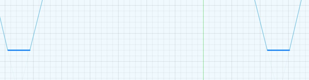
For acute angles and short lines in the “W” shape, I move the line between the two points that need filleting up, such that there’s more space between the points.
After these fixes, I have a design that can hopefully be cut on the wire EDM machine tomorrow.
Fabrication
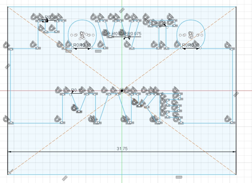
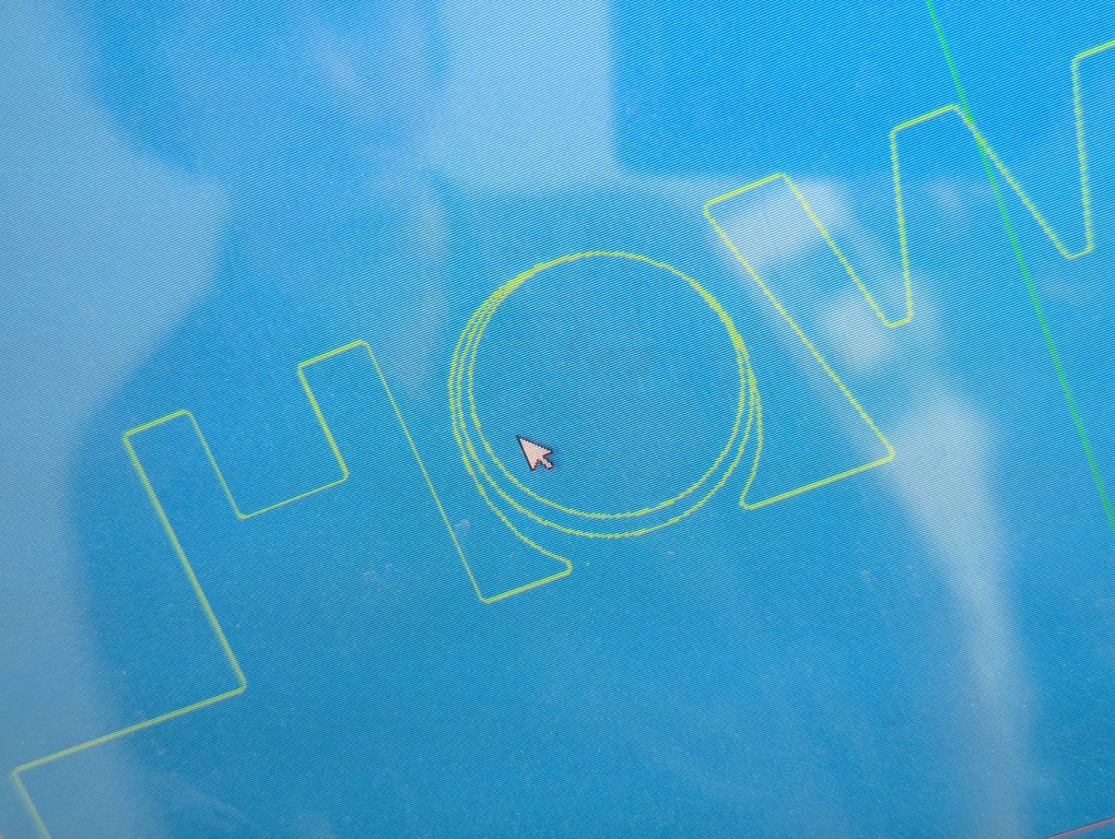
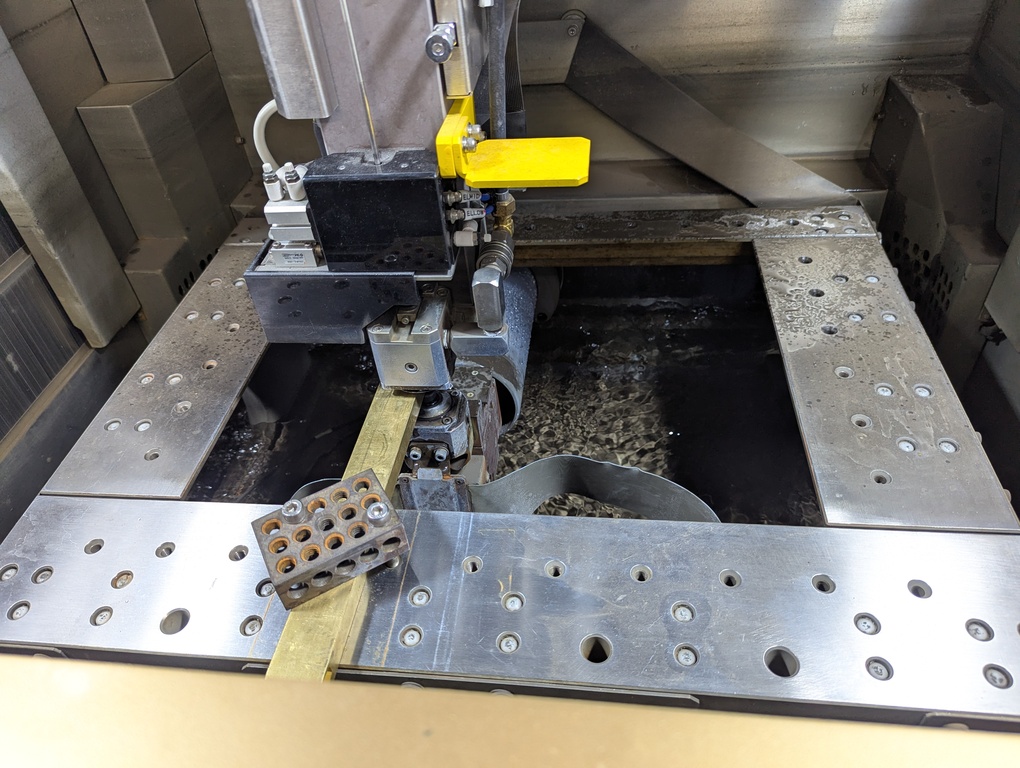
I’m meeting with Anthony to cut my design out of brass on the wire EDM machine. We’re running into many issues. When we first load the design into the machine’s software and process it there, we see a lot of weird circle shapes. We don’t know exactly what’s going on, but my uninformed intuition is that the DXF parser on the machine doesn’t like path definitions based on an origin, radius, start and end angles. At least I’m assuming that’s how parts of the paths are defined. In Fusion, it shows the centers of these circles as points (pictures above). The DXF spec must contain something about paths like that, but not each parser supports it? Not sure.
Anthony suggests projecting the “bad” path into a new sketch, hoping that it will clean up the path. We go through the process, load it back onto the machine and run into the same problem. The “O” shapes are the main problem, but some fillets have this issue, as well.
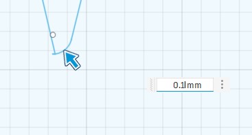
At this point we go back to bringing the Figma design into Fusion, replace the “O” shapes with a cleaner spline in fusion, extrude the sketch, apply fillets in 3d (0.15mm), project and export.
Now we have a clean path, but when generating the machine paths and simulating the g-code, the machine complains about a whole lot of things. We eventually realize that we didn’t scale the figma design after bringing it into fusion. We had always applied a 1/25.4 scaling operation on the machine to get it to the right size. That obviously also causes the fillets to get smaller. They seem to get too small for the machine and it complains.
We go back into fusion and fix everything accordingly, apply fillets after scaling, re-export and bring it onto the machine.
The machine is happy now. We try to run the g-codes.
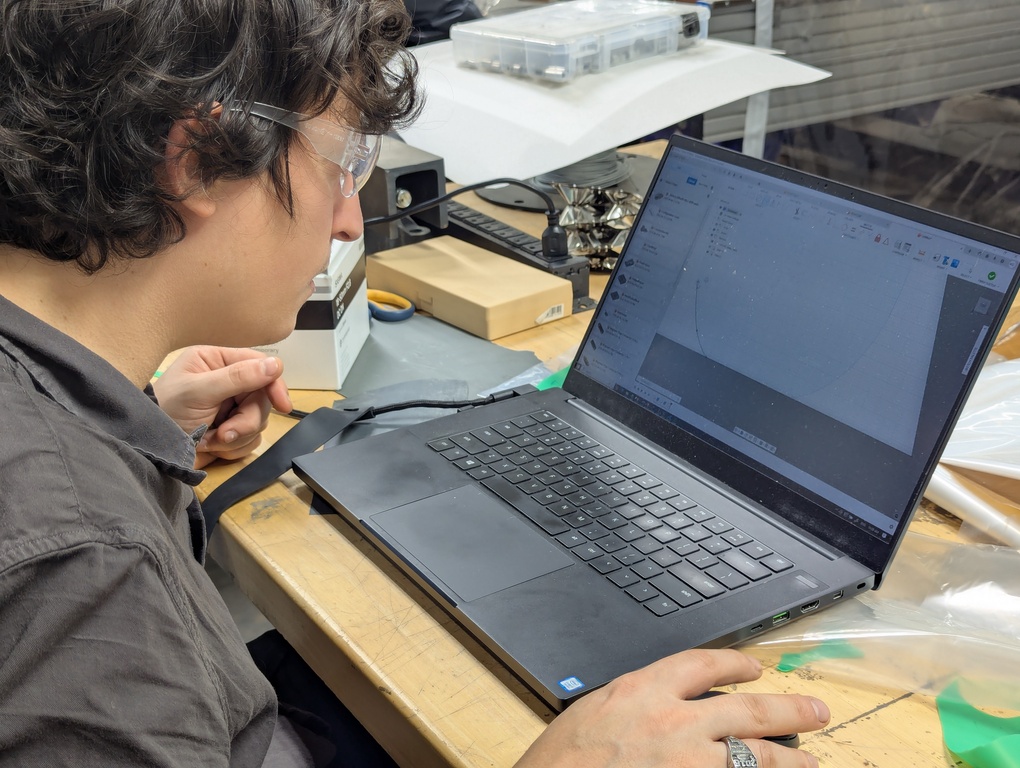
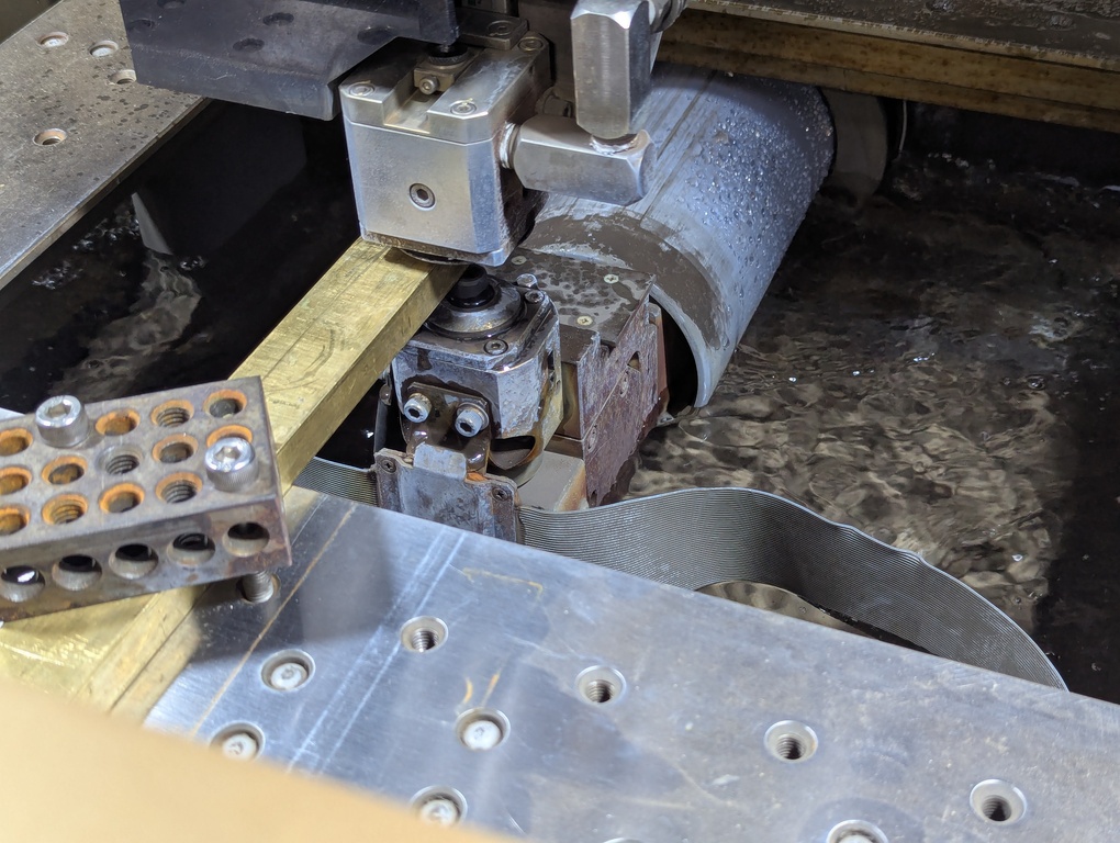
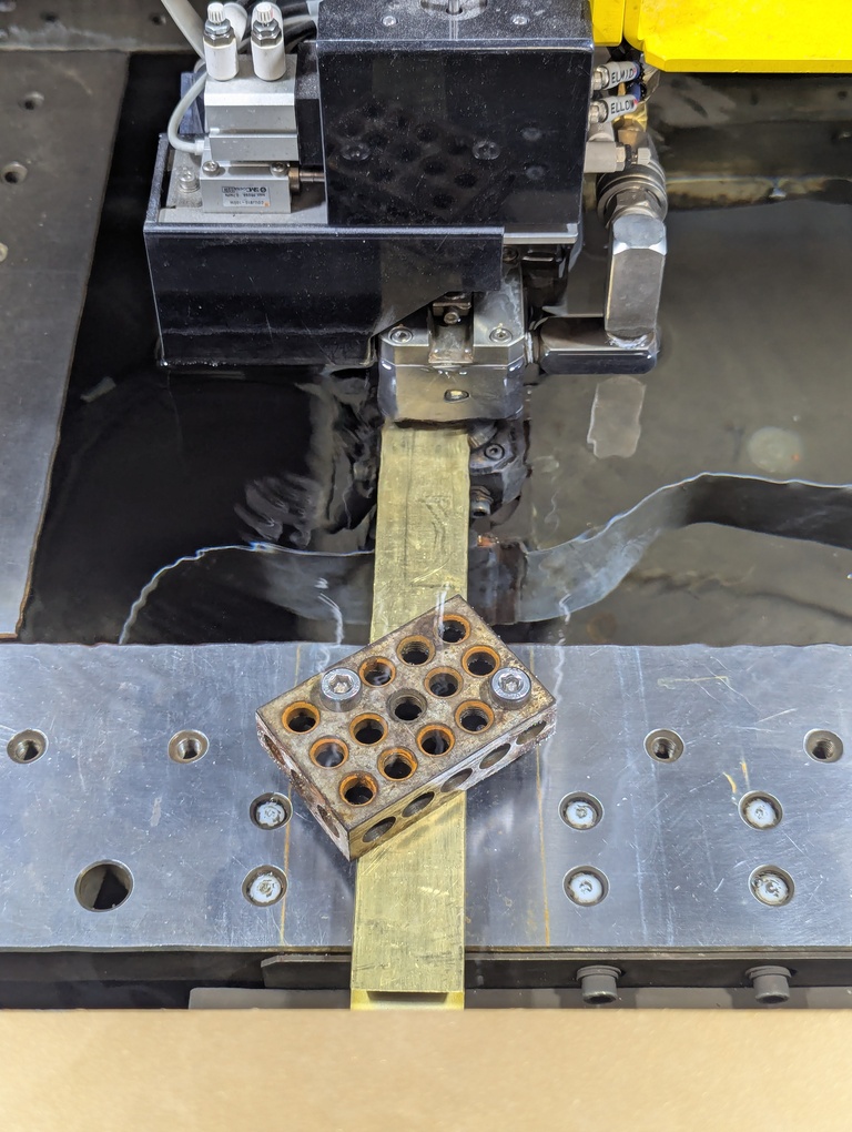
The image above shows the saint-like Anthony, trying to fix the DXF issues we’re experiencing.
We notice that there’s very little current going through the wire. For now we’re ignoring it. The wire is moving finally.
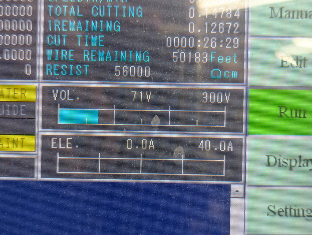
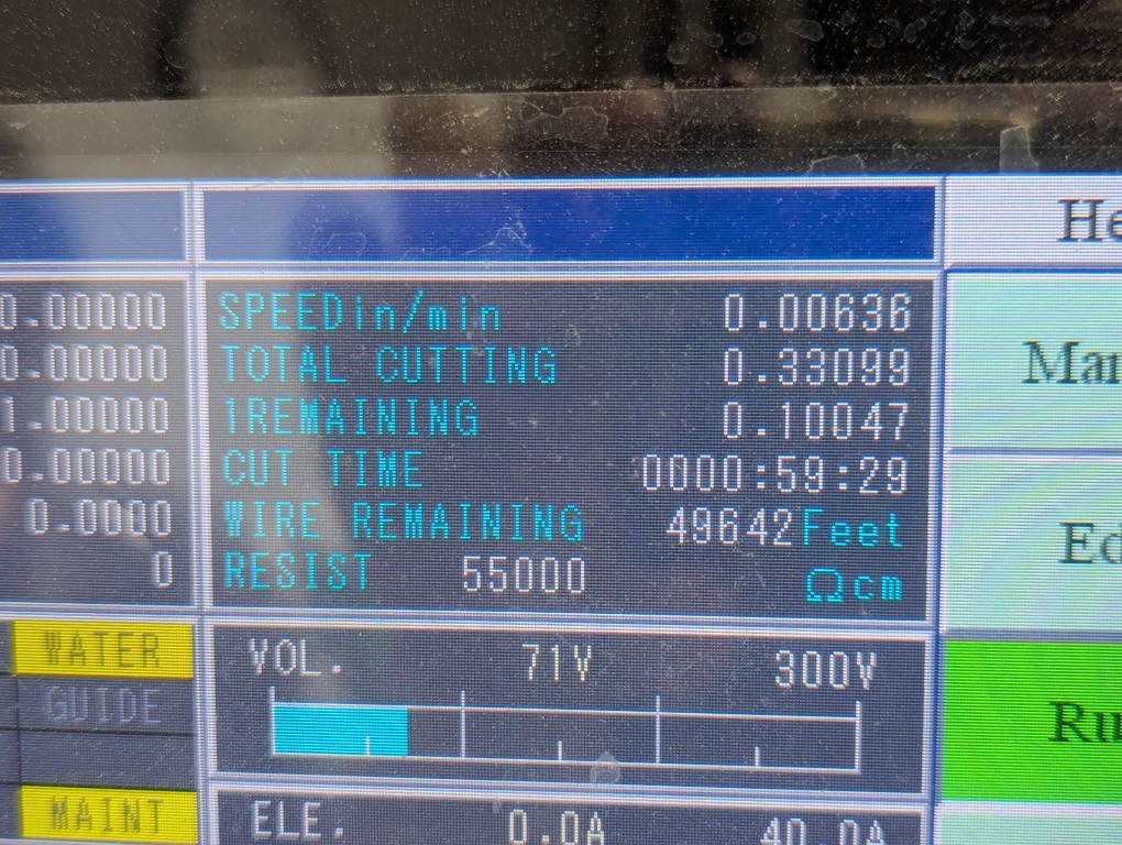
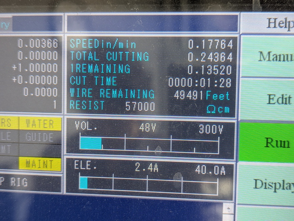
We notice that the cut takes a long time. After 1h, we had a 0.3in cut. That’s not gonna cut it (pun intended). We hypothesize that it’s something about the brass that makes the machine unhappy, potentially the oxidization on it. We switch to the aluminum stock that other people had more success with the day before. Pictures below show cutting speed before and after the switch. The aluminum makes for a much faster cut.
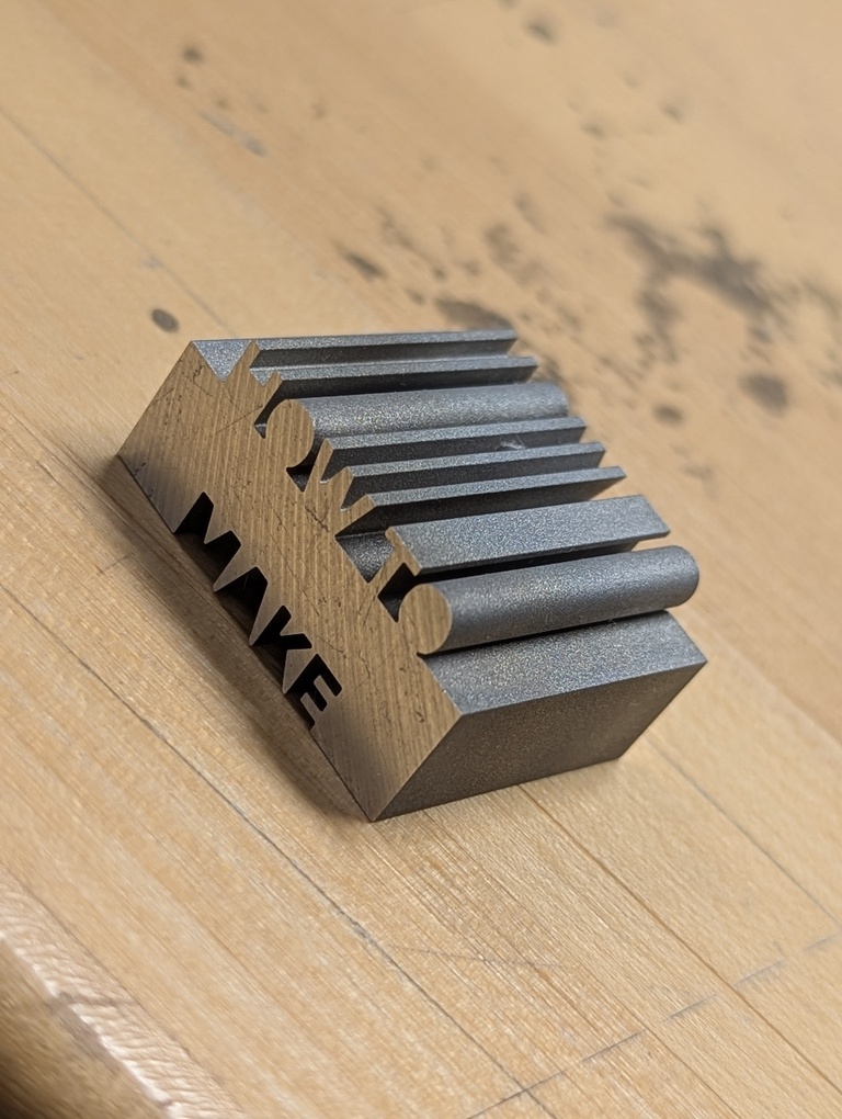
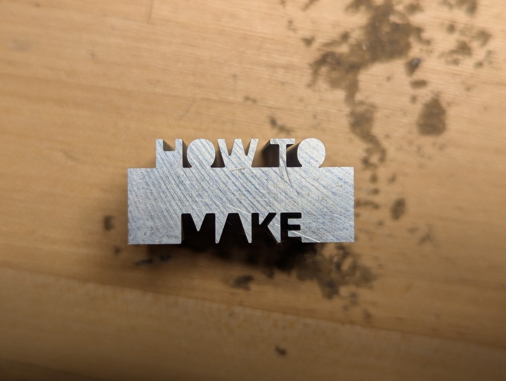
This new cut finishes successfully! All in all, the process took about 5h. The cut for the eventual final piece took 40min. The final piece can be seen below. I’m quite happy with it. We might try to run the job using the brass stock again. Anthony confirmed that rubbing off the oxidization layer improved the cutting speed significantly.
Anthony, again, thank you so much for all of your help today!