3D Printing/Scanning
It’s time to 3D print and scan. Exciting!
This week’s assignment
Here is the assignment as per the course website.
group assignment:
• test the design rules for your 3D printer(s)
individual assignment:
• design, document, and 3D print an object that could
  not be made subtractively (small, few cm3, limited by printer time)
• 3D scan an object (and optionally print it)
Group Assignment
I met up with Ben, Miranda, Sun and Yufeng to work on this week’s group assignment. It’s documented on the group page.
Individual Assignment
Design File: .f3d
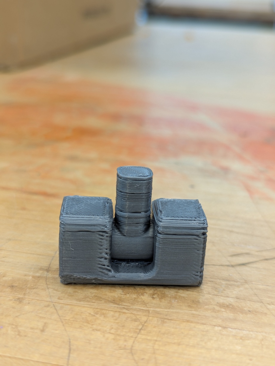
After learning how to use the 3D printer, I designed a test object that I could use as the baseline for this week’s assignment. My newly acquired CAD skills came in handy and I’m very happy that I’m able to make these sorts of designs relatively quickly now. The pictures below show what I came up with. It’s a hinge joint that allows for limited rotation in one axis.
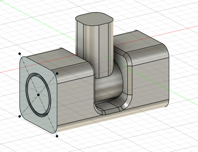
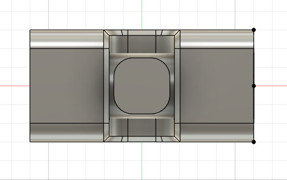
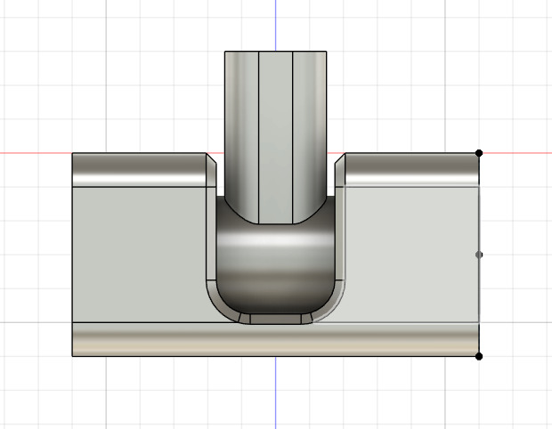
The idea is to make something that can’t be made subtractively and I think this design qualifies. That being said, I’m not particularly familiar with subtractive machining, so there might be ways to do this and I just don’t know. I used the below settings for my print. I also show the object in Prusa’s slicer.
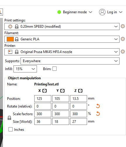
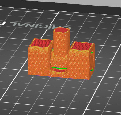
As you might have noticed if you looked at the design file, I have added a 3x scale to the object in Prusa’s software. That is because I designed the object too small. I made the same mistake when designing the cardboard construction kit in Week 2. Having made this mistake twice, I’ll try to be more conscious about imagining the right dimensions when designing. Luckily it’s very easy to change the scale on a model directly in Prusa’s slicing software for something simple that doesn’t need exact measurements like this.
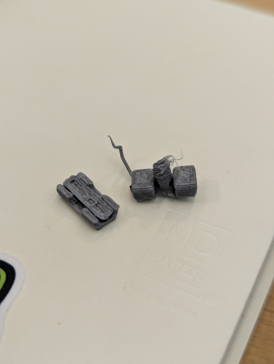
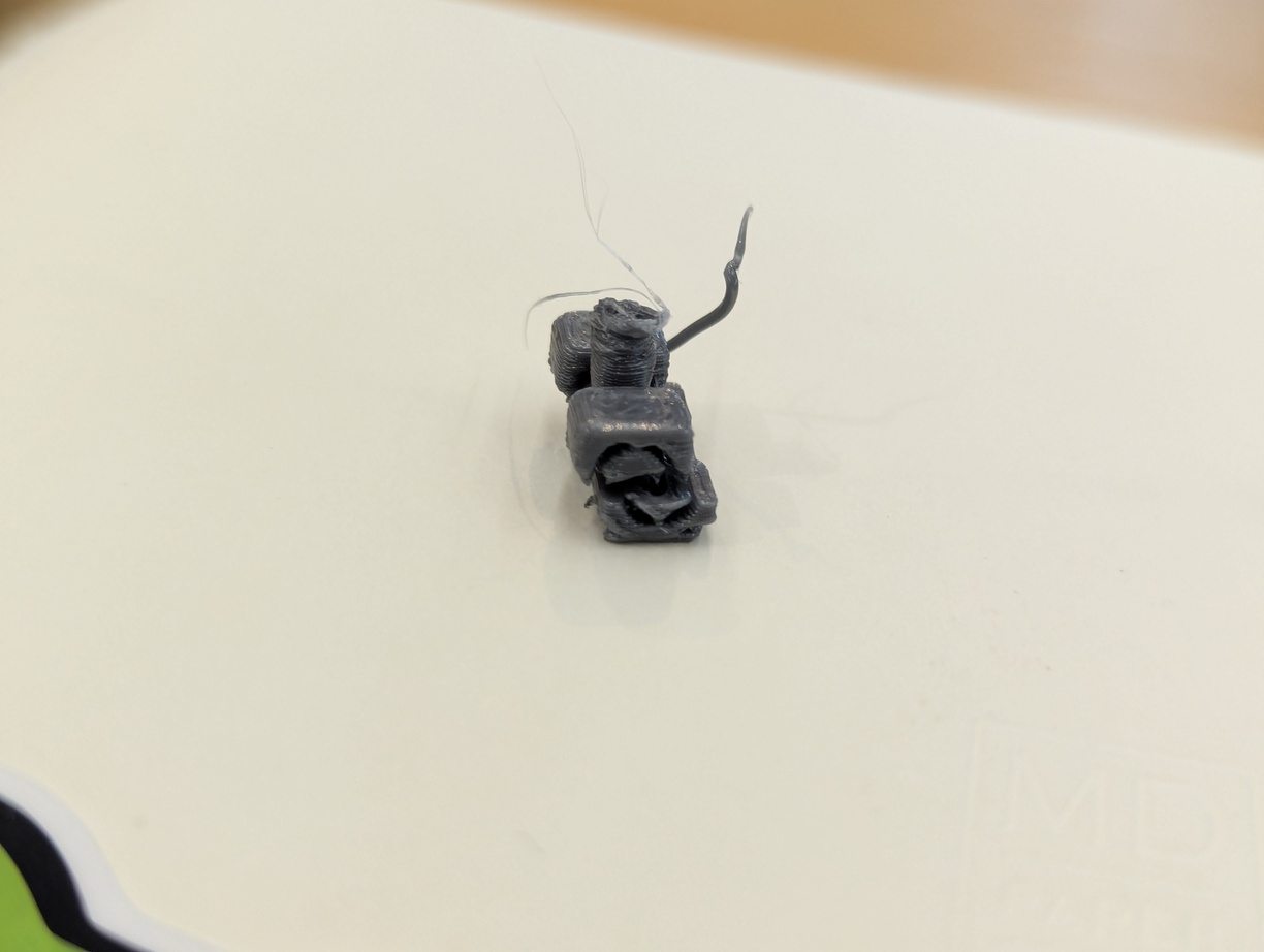
So, my first model came out too small, but I also broke it in another way. For some reason, my mental model was that the machine would pull the 3d model off of the USB key onto some local storage and drive the nozzle from there. Or at least hold the model in some sort of ephemeral memory while working on it. That doesn’t seem to be the case. When I removed the USB key to store my newly scaled model, while the small part was still being fabricated, the 3D printer abandoned the print job and threw an error. When putting the USB key back in, it continued the print, but at that point the part must’ve cooled down so much that the new layers didn’t bond with the previous layers. Pictures below!
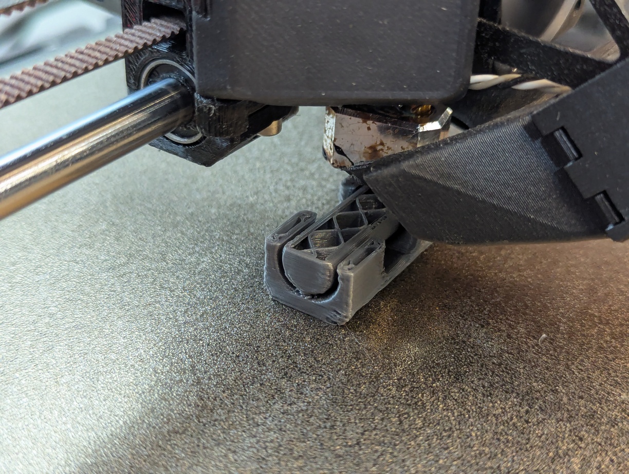
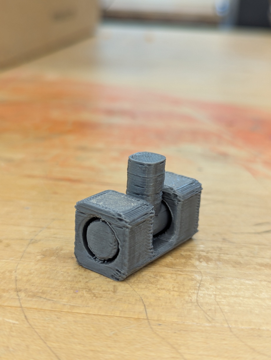
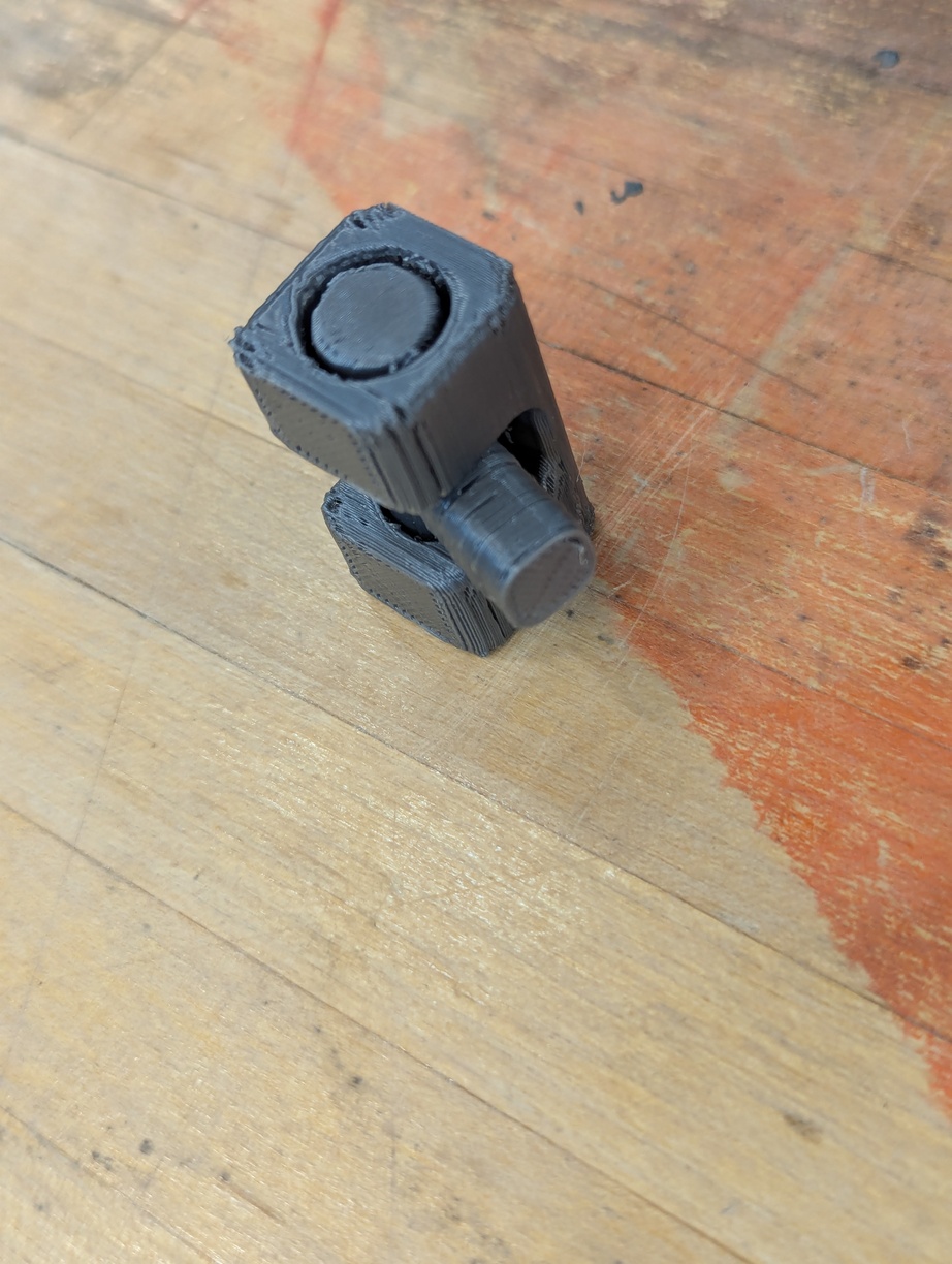
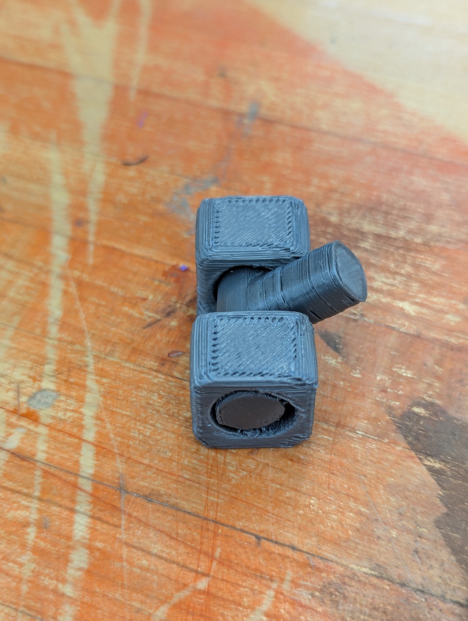
The new larger model worked much better and came out looking ok. I had the Prusa software add supports between the 2 separate components and used some force to rotate the hinge enough to break up the supports. There are still some support pieces stuck in the joint, but it generally works as intended.
Instead of continuing down a more artistic path, creating nicer models and printing interesting shapes, I decided to prepare for my final project and learn how to assemble multiple pieces and/or attach PCBs to prints. I mentioned to Alfonso that I’d love to learn how to do heat set inserts and he was incredibly generous with his time this week. Thank you so much, Alfonso! I learned a lot and had a lot of fun. In the following, I’ll describe how I played with 3 different ways to put a screw into printed pieces, - with a brief reflection about what method I like best.
Screw This! - Construction
The 3 methods tests are:
- Heat Set Inserts
- Tapped Plastic Threads
- Embedded Nuts
Heat Set Inserts
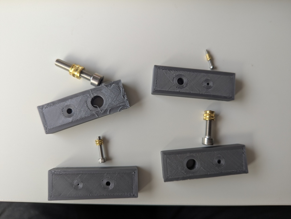
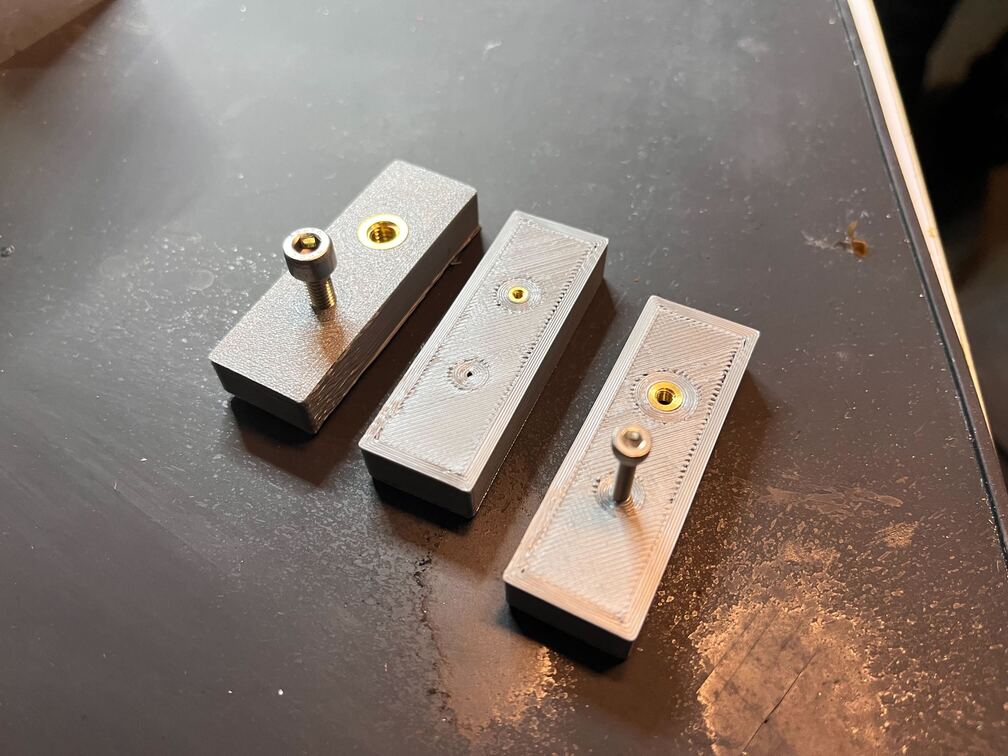
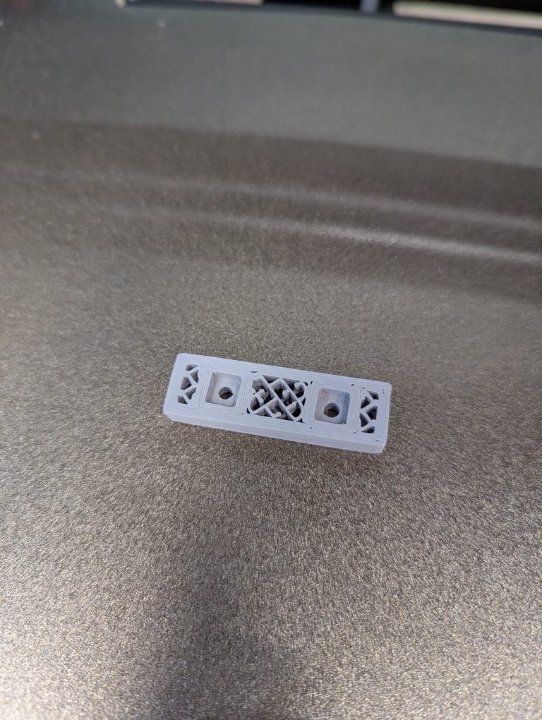
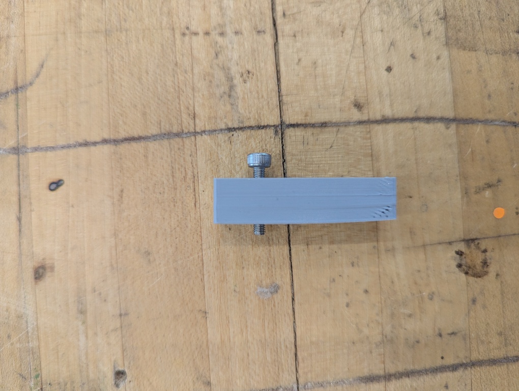
I constructed some test blocks in Fusion360 based on the size of screws and inserts that Alfonso gave me. You can find the construction file in the list of files on the right. See pictures of what the blocks and screws look like below.
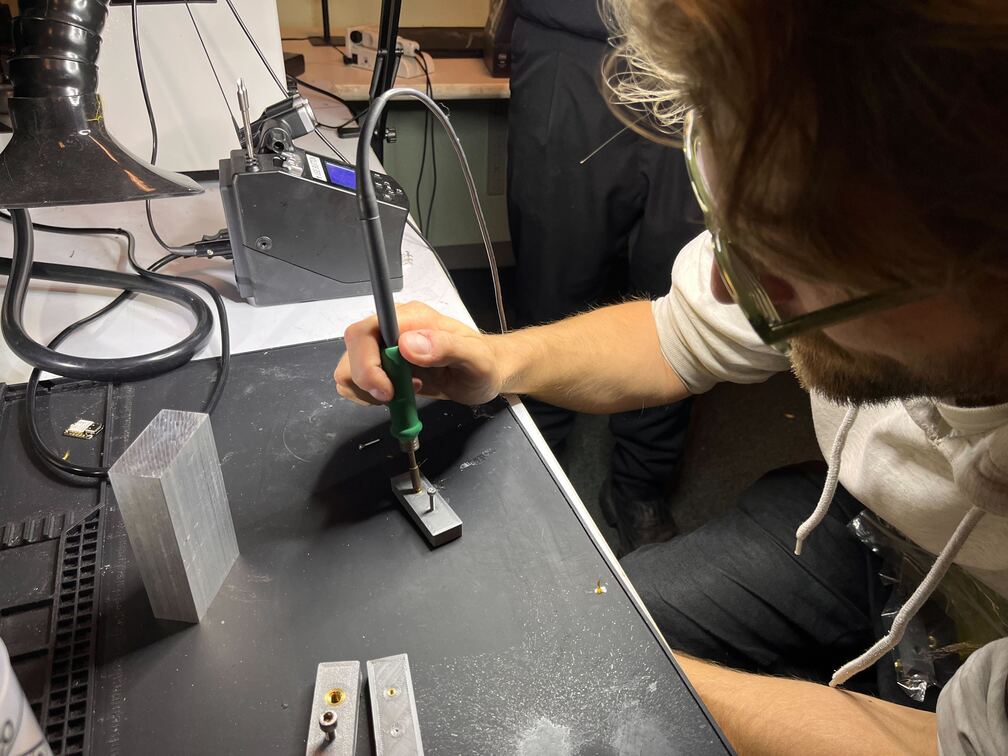
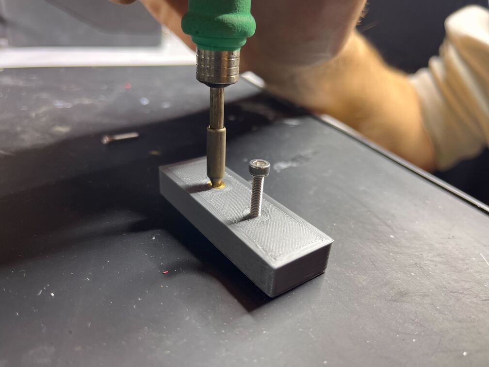
The process is as simple as it is satisfying. Using a soldering iron, you heat up the inserts and slowly push them into the plastic. The plastic melts around the insert, locking it in place when it cools. Putting the screw into the inserts is obviously super smooth. I’ve seen people do this online before taking the course and always admired how neat it looks.
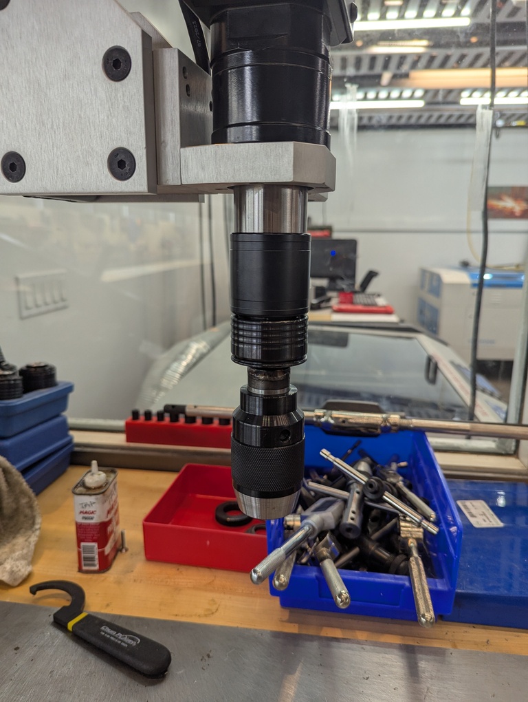
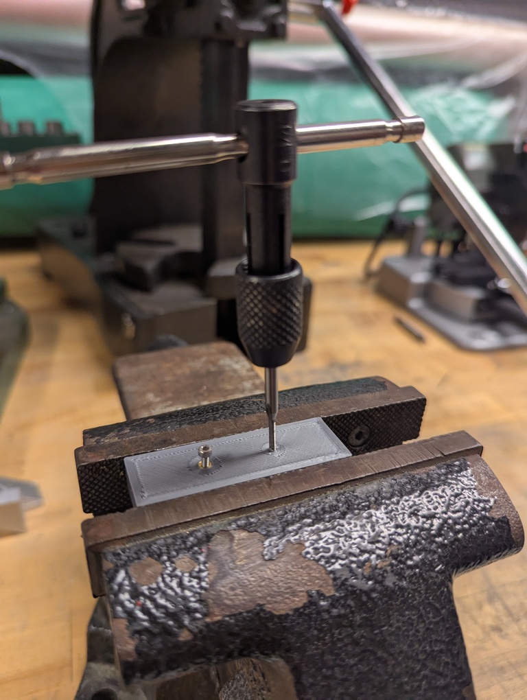
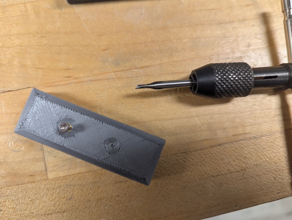
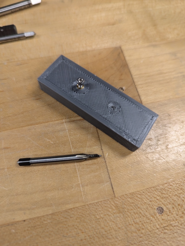
Tapped Plastic Threads
As an alternative, you can use a tap bit to put the threading into the plastic directly. I used the machine in the workshop for the larger screws, but didn’t trust the alignment of the smallest bit. When looking at the rotating bit and feeling how it moves with my finger, I decided that it rotates off-axis quite a bit and I didn’t want to risk my precious 3D printed part. Having a hole made by a wobbly bit didn’t seem like the best idea. So, instead I opted for a manual tool that Alfonso gave me access to. Clearly he shouldn’t have. It didn’t take me long to break the bit. I add pictures as evidence of my crimes below. The bit is much more fragile than I anticipated and after putting it a centimeter or so into the plastic, it breaks very easily. So, that ruined that printed block a little bit as it now has a piece of metal stuck in it, but it was a good learning experience. The holes for the larger screws worked out ok, though. I’m grateful for the opportunity to fail and make mistakes in a safe environment.
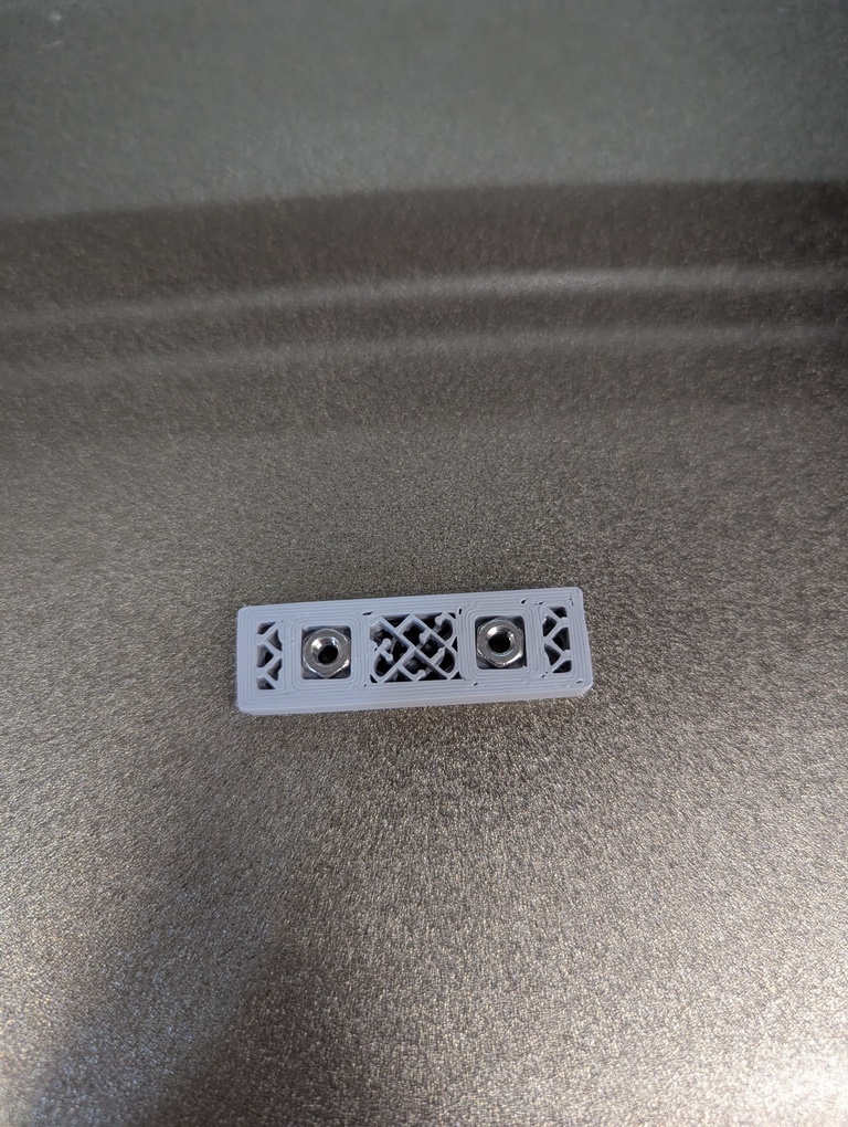
Embedded Nuts
While working on the tapped plastic threading, Neil came into the workshop and suggested making a horizontal slit to slide a nut in. We briefly chatted about an alternative solution where you put a pause instruction into the gcode for the printer. That allows you to put a nut into the part while it’s still being assembled, and have the printer then cover the nut. I had seen people do it with magnets before and decided that I want to try the process. The images below illustrate the process once you have the design file and are ready to print.
HowTo
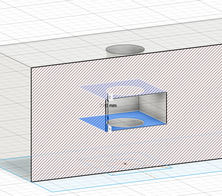
Fabricating the block with embedded nuts gave me an opportunity to learn how to use the Section Analysis tool in Fusion. I made the hole for the nut in my design (and parametrized the nut height which came in handy later), but I also wanted to verify that it has the right height. Using the Measure tool directly didn’t work because the hole is within the volume and covered by surfaces. The screenshot in the gallery below shows how the Section Analysis tool shows a cross section that will then allow you to measure between two surfaces.
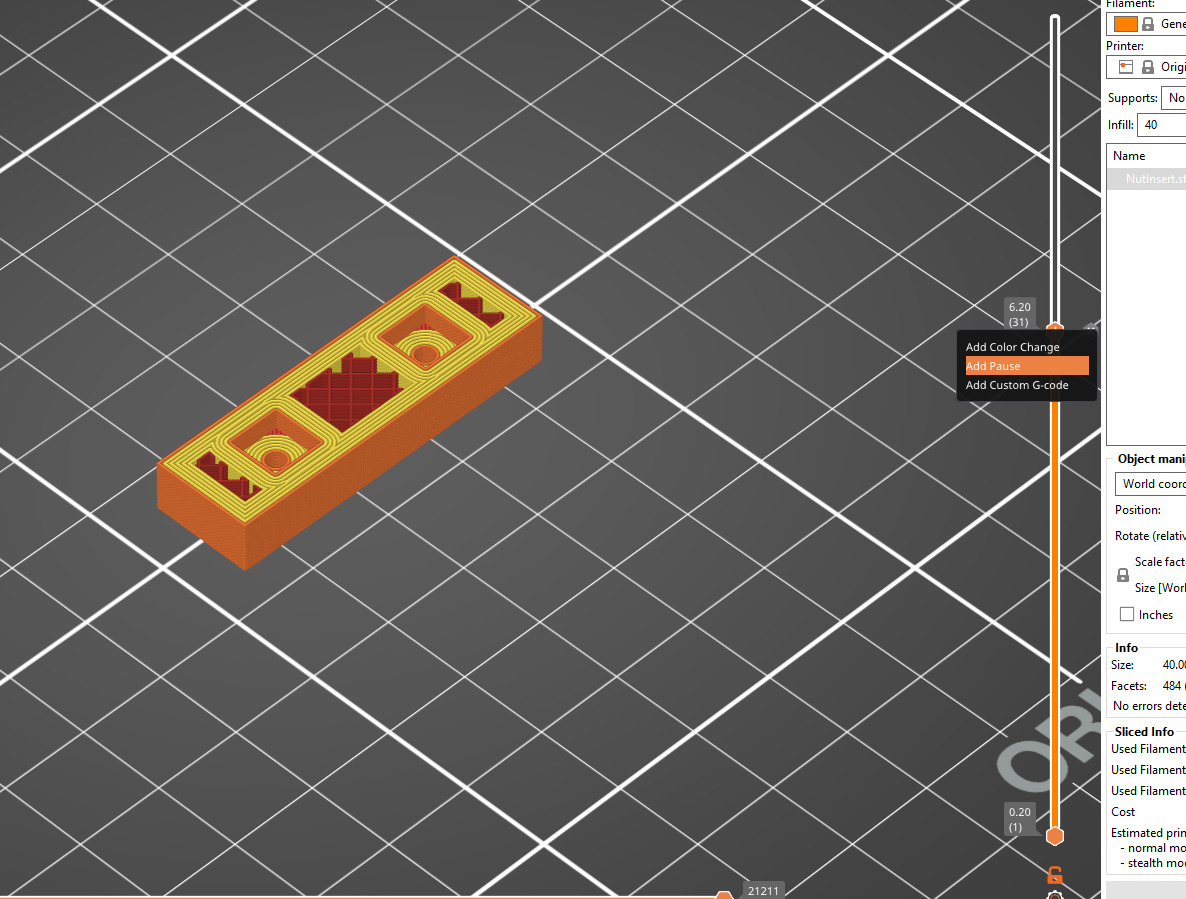
The next screenshot shows how to put the pause instruction into the gcode. Using Prusa’s slicing software, the vertical slider lets you skip through machine paths. Stop it where you think you’ll want to drop in the nut, right click the slider handle and click Add Pause. It’ll ask you for a message to display on the printer when it pauses.
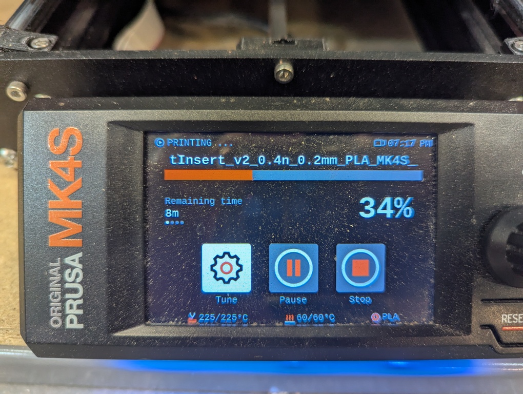
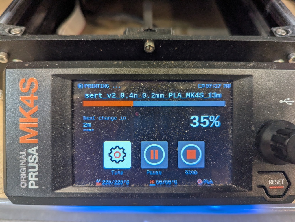
The remaining photos in the gallery below show a nifty feature of the printer. It cycles through a few messages while it prints. It’ll show you how much longer the print will take in total, but also how much longer until the next pause which is when you as the user will need to step in, drop in the nut in this case, and then explicitly resume the print.
Screw This! - Destruction
Now, the purpose of producing these blocks with 3 ways to attach screws was to identify which one can take the most force before the screw breaks loose. Alfonso suggested this when we talked about heat set inserts and I was eager to try. He spent a lot of time with me on these experiments and I’m very grateful. Thank you!
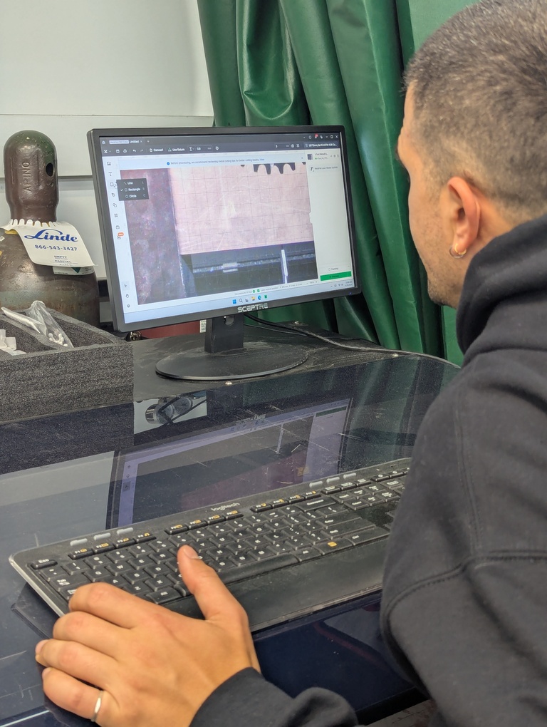
Alfonso made a little rig in xtool’s “design” software directly on the machine. Below you can see him while whipping it up in no time. I have recorded the machining process as well. Video below!
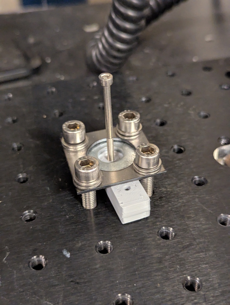
Below you can see how we used the rig to attach the plastic block to the machine that performed the uniaxial tension tests for us. Since the blocks were slightly to big for the rig, I had a chance to use the sander in the workshop.
Here are videos of measuring the forces in the following order:
- Embedded nut (m3)
- Heat Set Insert (m3)
- Tap (m3)
- Heat Set Insert (m2)
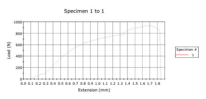
Results
Results are below and in the same order. (I need to make my own graphs from the raw data to make this prettier).
To summarize the results:
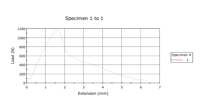
- Pulling the embedded nut (m3) out of the block requires the most force.
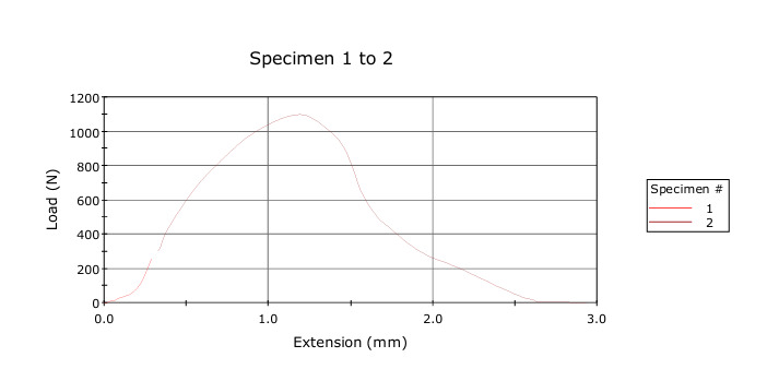
- The heat set insert (m3) is a very close second. This was surprising to me.
- The smaller heat set insert (m2) held on for a long time and required almost as much force as the m3 variant.
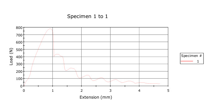
- The tap is the weakest of the bunch (as expected) but produces an interesting pattern where presumable the nature of the threads create a non-linear force response.
Embedded nut (m3)
Heat Set Insert (m3)
Tap (m3)
Heat Set Insert (m2)
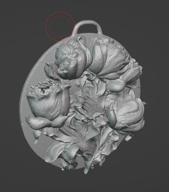
AI Workflows
Eitan and I also looked into AI workflows this week. He is doing some interesting work with musical instruments and based on that, we also briefly explored creating jewellery with flowers. We created an image in Midjourney that we then brought into Meshy to obtain a 3D mesh. I brought the resulting mesh into blender and added a little hook so that the object, when printed, could be worn on a necklace. See the image below. Unfortunately, we weren’t able to figure out the printer we wanted to use for this object. While it showed its IP, the software for managing print jobs couldn’t find it on the network. Something to explore more in the future!
3D Scanning
I had to keep it pretty simple for the scanning portion of the week. I did a scan of my project in a previous week, but wanted to also use Scaniverse to scan a mesh (the previous scan was 3DGS). Below is the result. I was trying to scan my thermos and while it looks like it reproduced the textures and (static) lighting fairly well, the mesh isn’t the best. I created this by walking around the object 3 times, recording it at different heights and angles.
Conclusion
I really enjoyed this week - specifically doing the heat set inserts and working with Alfonso on the tension tests. For my final project, I definitely want to use the heat set inserts even though I don’t anticipate large loads. I just really like how they look and I want to make my final project look as neat as possible. That includes mounting the PCB(s) in the housing.
As part of this week I have also ordered components from DigiKey that I want to start playing with: ESP32s, batteries and sockets for the display’s ribbon connector.