group assignment:
• measure the power consumption of an output device
individual assignment:
• add an output device to a microcontroller board you've designed,
  and program it to do something
Group Assignment
For the group assignment, we met in the Electronics Lab in the basement and looked at the power consumption of an output device. Ben and Ceci explained how to use the volt meter for that purpose. We used a program that Sun wrote to cycle through different amplitudes and frequencies and then measured the power consumption of a speaker for each of these configurations. The documentation can be found here.
Individual Assignment
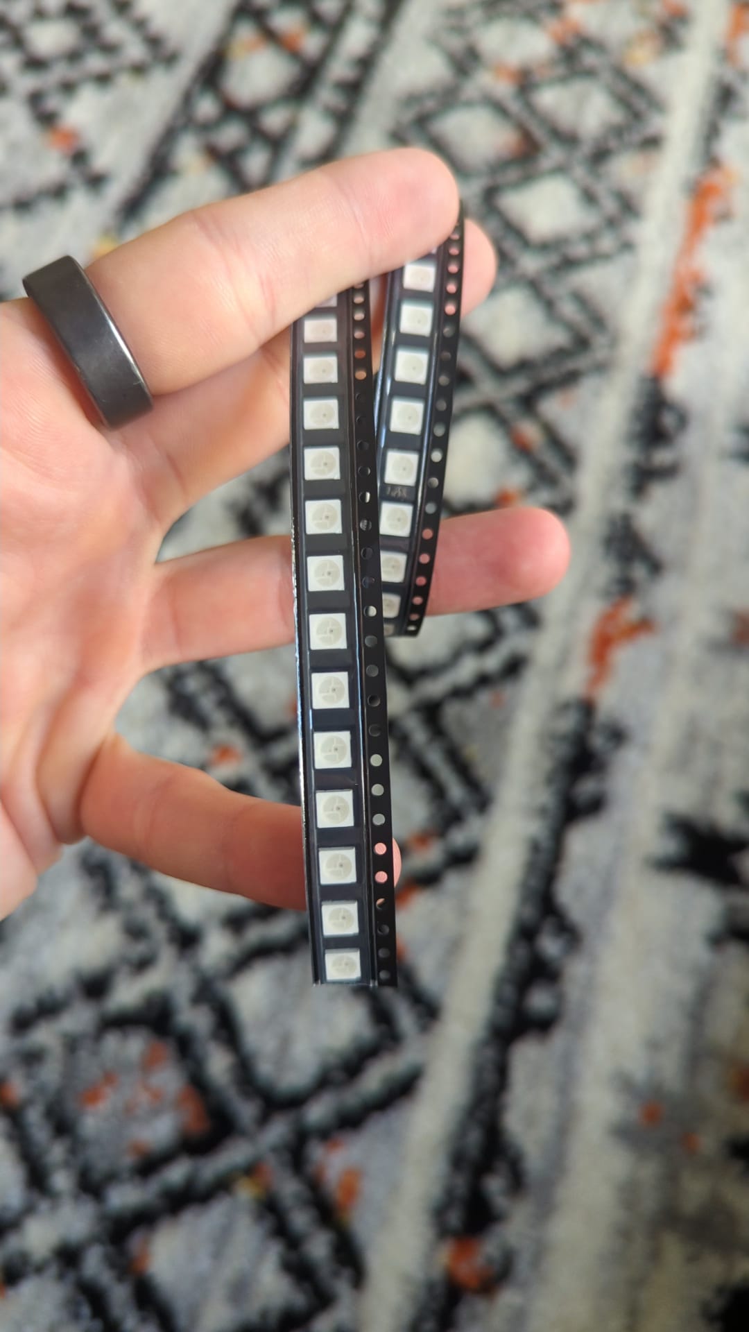
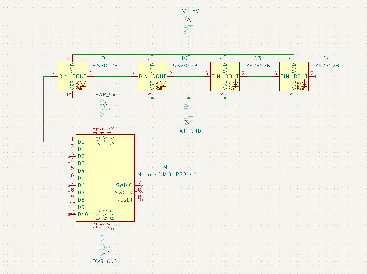
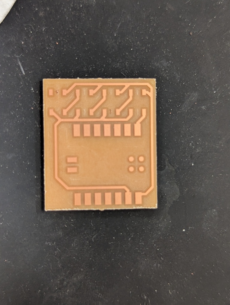
For this week’s assignment, I’m keeping it very simple. I’m designing a board that uses the RP2040 Xiao microcontroller to control 4 WS2812B LEDs. I have a couple of these still kicking around from an old AliExpress order. I have actually never used these specific ones and since they have the leads mostly hidden at the bottom, it’ll be a good exercise to solder them onto the board. I have never used paste and hot air before.
PCB design
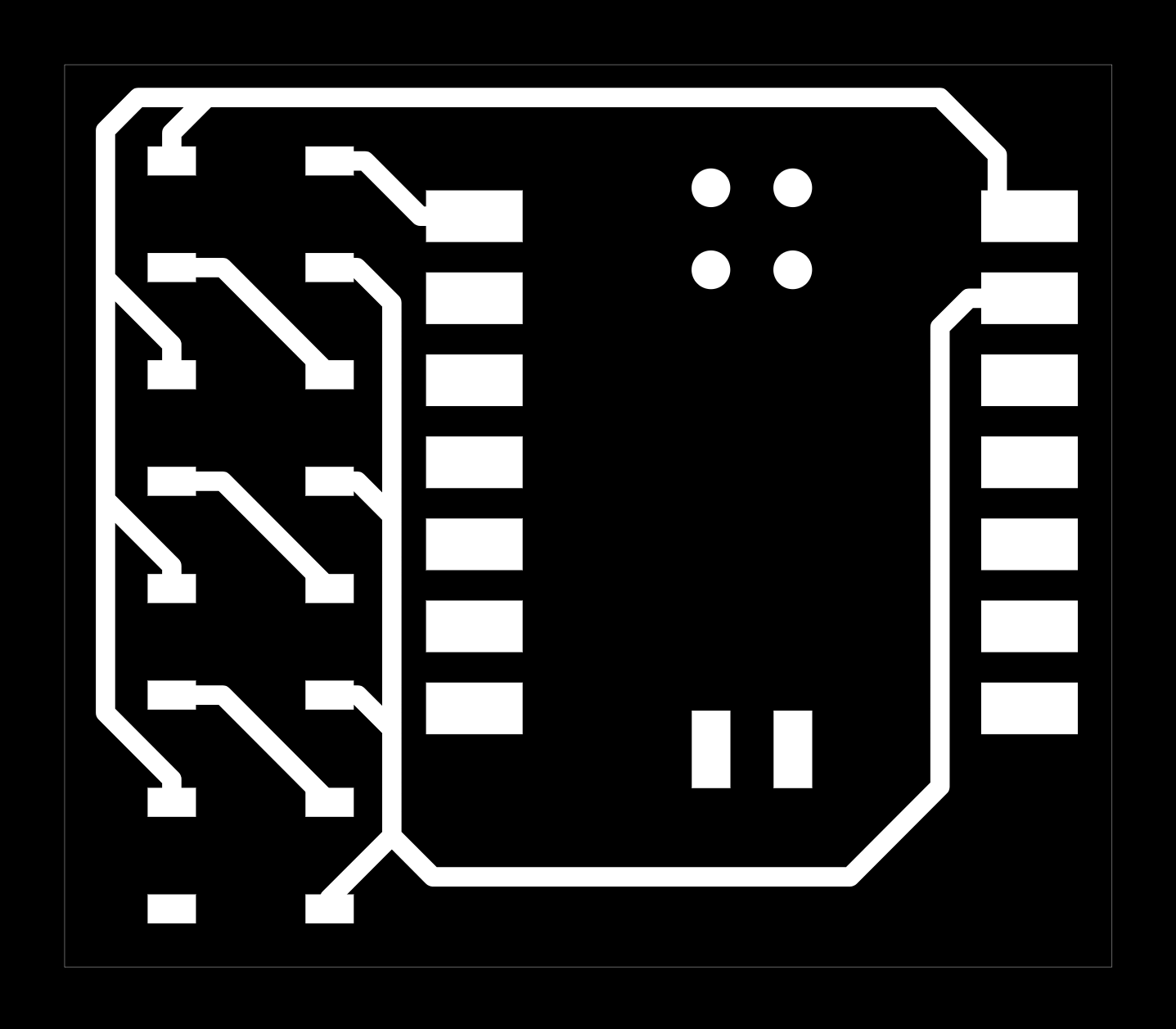
The schematic for the board is straight-forward. The thing to know about these particular LEDs is that you chain them by connecting the data out of the first to the data in of the second and so forth. You can then address these via their index in the chain in code when you assign colors.
Soldering
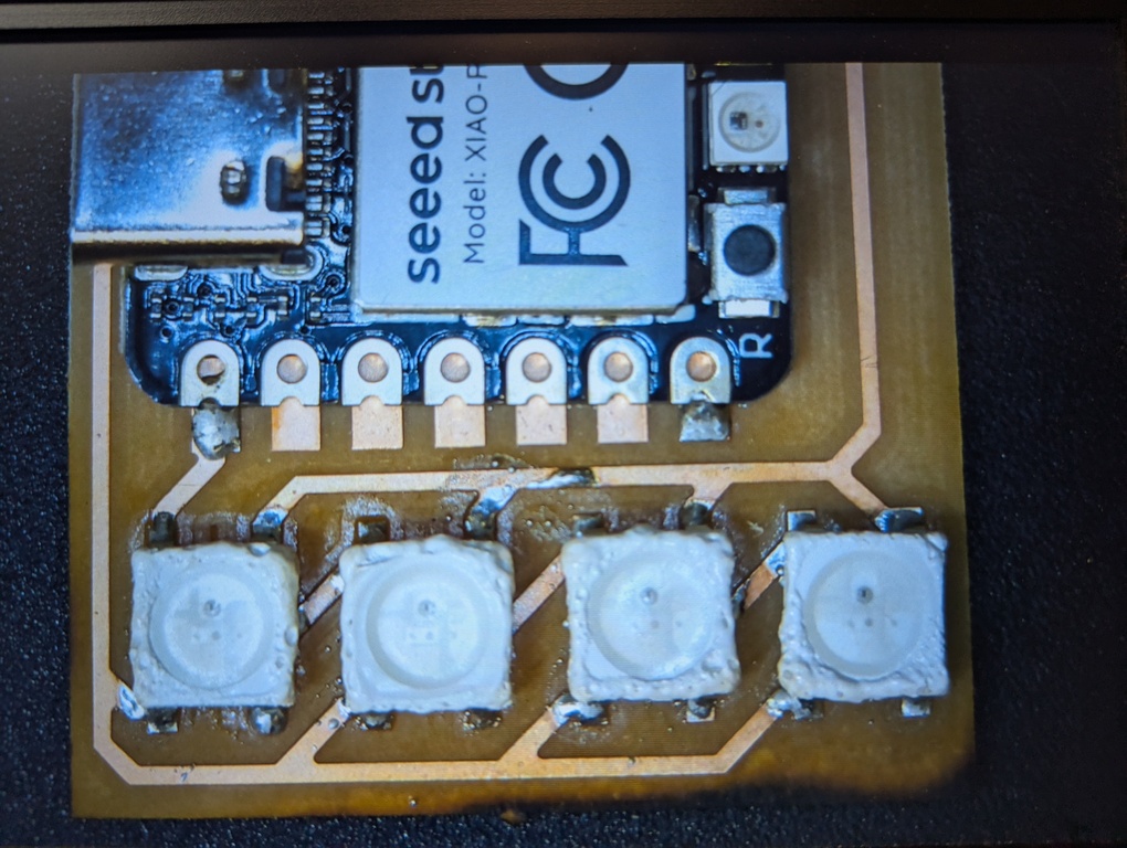
I had never used hot air and paste before. Luckily it’s not that complicated and worked really well. I soldered the XIAO by hand, but then applied solder paste to the 4 pads of each LED. I then placed the LEDs and started to apply the hot air. For LED placement, note that these LEDs have a little triangular indicator in one corner of the housing. That’s the GND pin!
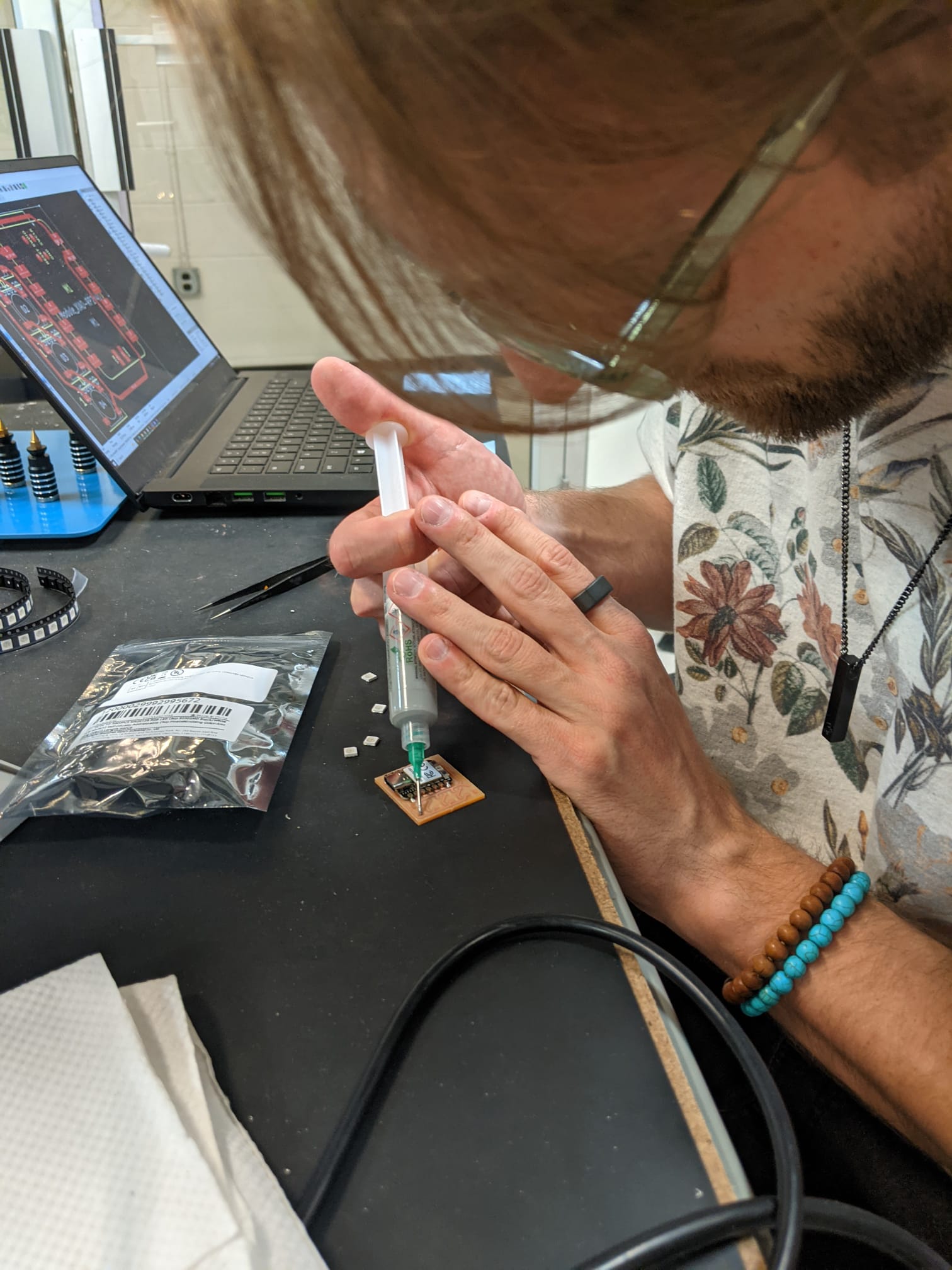
Learning: I think I need to apply the hot air in circular motions a bit more. As you can see below, the housing of the LEDs is a little burned and I think that’s because I applied the hot air to certain spots for too long instead of uniformly heating up the entire area. The board itself is a little scorched, as well. I have actually tried to use hot air again for some progress on my final project and felt like I got the hang of it a bit more.
Code
Here’s the code for the board. It’s written in MicroPython. For the RP2040 boards, I usually install MicroPython via Thonny. Just hold down the B button on the board, connect it to USB, select the board in the bottom right of the Thonny UI and have it install the latest MicroPython.
For these LEDs, using the neopixel library is very convenient and as you can see, the resulting code is not very complicated.
Code
import machine, neopixel
np = neopixel.NeoPixel(machine.Pin(26), 4)

np[0] = (255, 0, 0)
np[1] = (0, 255, 0)
np[2] = (0, 0, 255)
np[3] = (0, 0, 255)

np.write()
Result
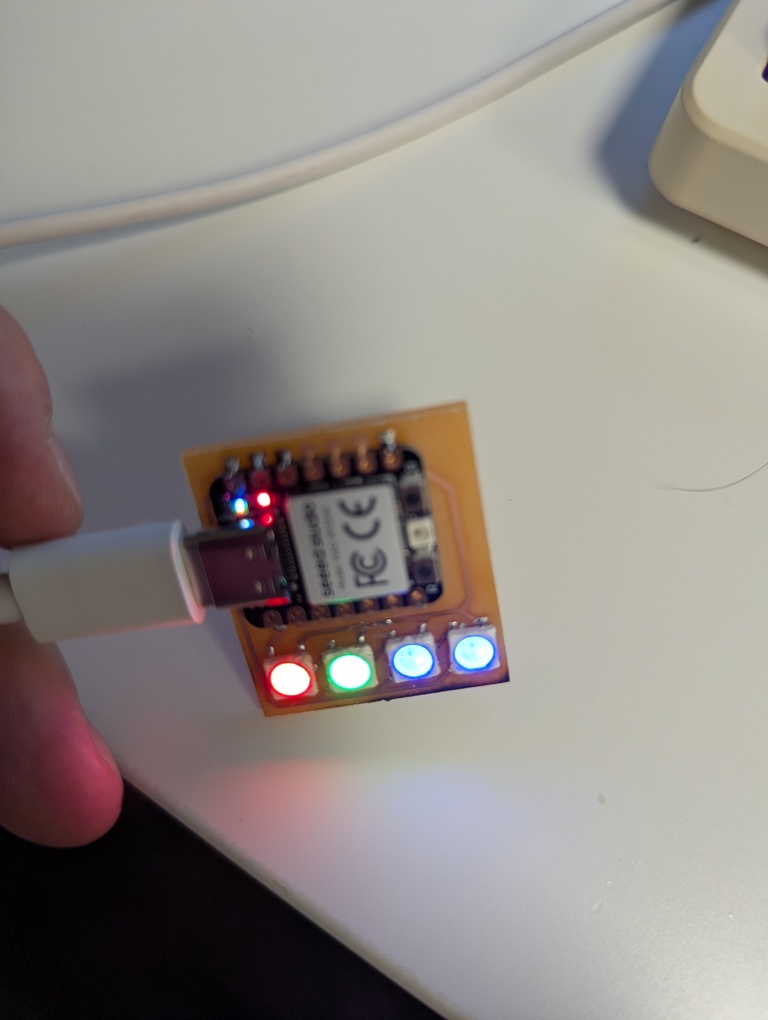
That’s it for this week! It was fun to use solder paste and hot air for the first time and I can see myself using this workflow more often. I’ll have to get better at it to not burn components, but it worked well for a first attempt.