Parametric construction kit: hands
My inspiration for this project was a kinetic sculpture I made a while ago modelled after my own left hand:
Sketchy sketchy + fusion fun times
First I did some sketches to get a sense of what pieces I would be making and generally what they would look like.
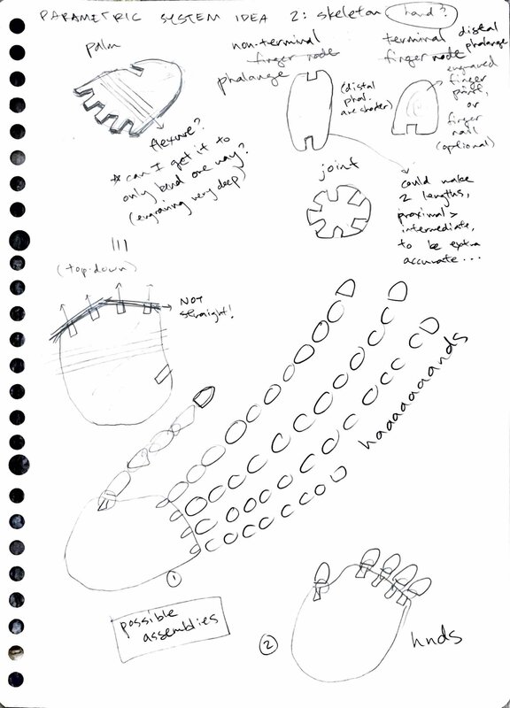
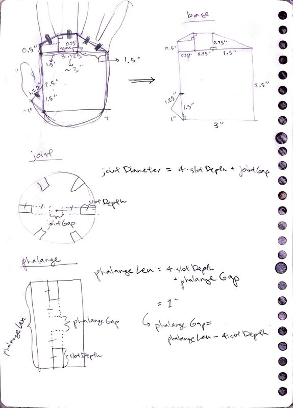
Then, I was ready to move into CAD software (I’m using Fusion 360)! I received wise advice from my friend Ben: decompose each shape into basic geometric objects first to make dimensioning easier, then add the curves and nice touches later. So, after measuring my left hand I drew out these sketches for the simplified forms of the palm, joint, and phalange (finger segment):
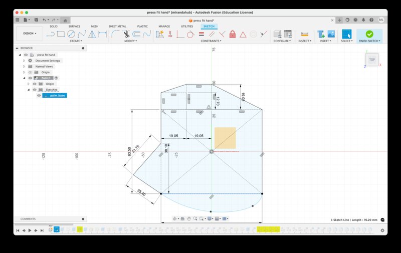
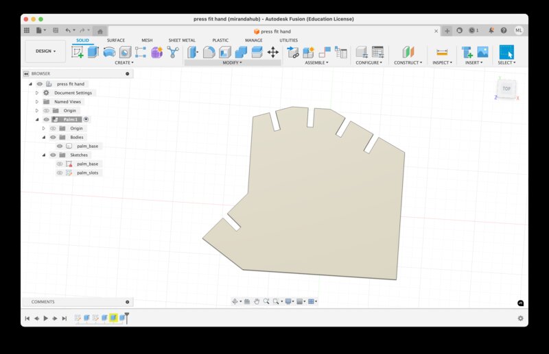
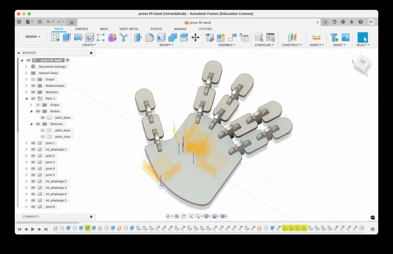
I implemented these into a sketch for the base palm (ignore the curve at the bottom, I added that later but forgot to take a screengrab at this point so I captured this after all was done).
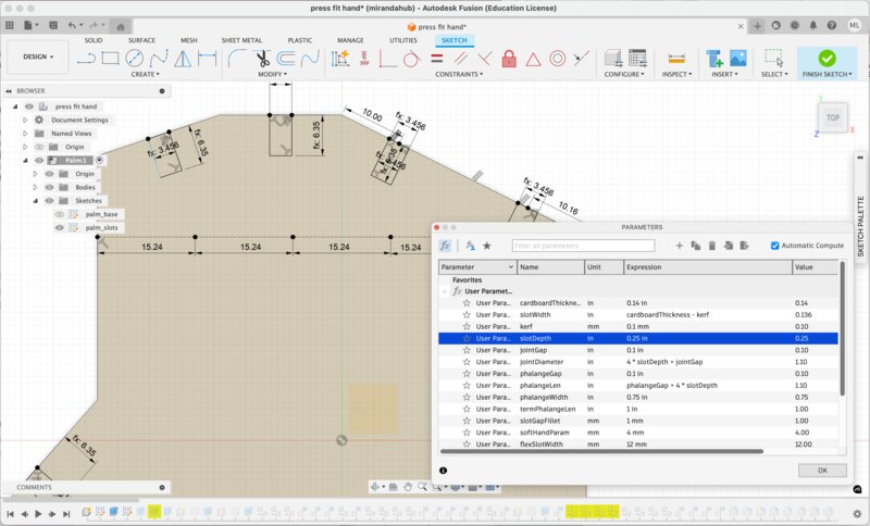
In another sketch, I parametrized the slot depth and width and used these to add slots to the extruded palm. I accounted for the kerf by subtracting the approximate kerf value from my initial (desired) slot width.
Finally I had a nice geometric palm to start with:
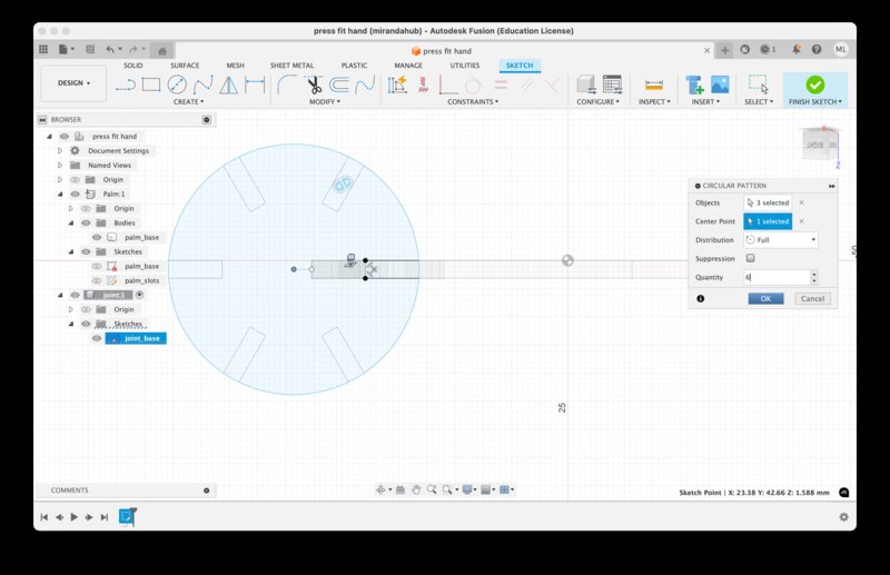
Next, I modelled the joint by similarly beginning with the very simple sketch I had made (in this case, a circle). I drew this sketch off of one of the inner faces of the slot in the palm to avoid having to assemble it later. Then I added one slot and used the circular pattern tool to make 6 evenly distributed slots around the circle.
After the joint I made the (intermediate) phalange, which is just a rectangle with two slots. Here I made a construction line across the middle of the rectangle and mirrored my slot across.
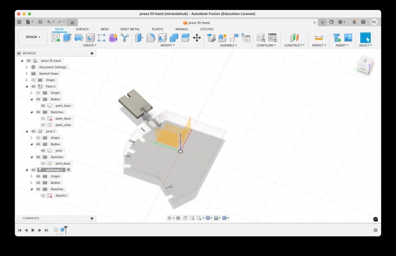
The terminal phalanges (with only one slot, e.g. the “fingertip”) were trivial to make, just a rectangle with one slot. In keeping with anatomical accuracy I made them slightly shorter than the intermediate phalanges. I then copy-pasted my components like crazy and used the Assemble functionality to put the pieces together. For each interface between a joint and a phalange I had to add three face-to-face constraints (one for each of X, Y, Z) to ensure the slots were fully slotted together.
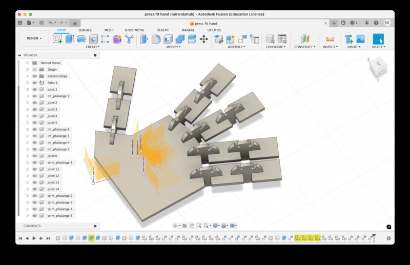
(I realize now that I modelled the hand with one fewer joint in each of the pointer - pinky fingers, oops.)
Spiral design: laser cutting & learning as I go
In the name of Rapid Prototyping I cut and assembled this basic structure on the XTOOL P2 using 87% power and 37 mm/s speed, just to sanity check.
Mostly, everything looked good! I had a small hiccup where since my cardboard was bowed, though I had set the focus height of the laser to my measured material thickness, it still began to pull the cardboard piece around, so I had to stop the cut and manually quick-measure the highest point of the material, which ended up being more than twice the thickness of the material. Also, my joints were way too loose. I had measured my cardboard to be aroudn 0.16 inches thick so I’d set my cardboardThickness parameter to 0.16 inches in fusion, but everything was falling apart. So, I ran a small test to see what material thickness value would give me the joint clearance I was looking for:
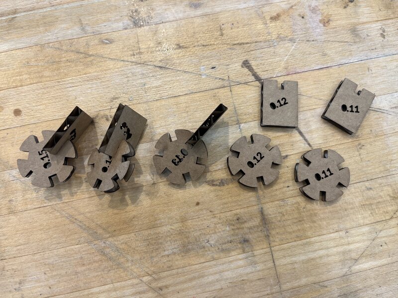
I decided to go with 0.14”, since even after I deformed the cardboard as I tried to slot the slots together the joints still held well.
Smoothing edges, bending the palm
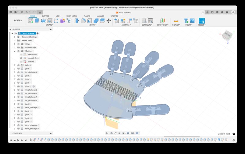
Of course, hands are soft. It was important to me that I make the hand more organic-looking, by smoothing out all the sharp corners from my base sketch. I added filleting to opening of the slots as well, and used the same fillet tool to smooth any corners. I also added a curved line to the bottom of the palm base. When all that was done, my model looked like this:
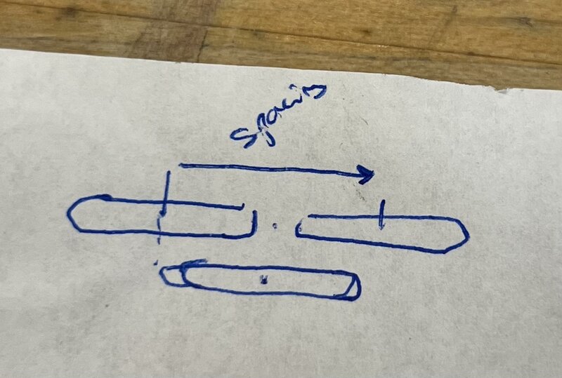
Next, I wanted to implement flexure across the palm. I was noodling with some online flexure patterns when Alfonso happened to walk by. He drew me a tiny drawing of the most fundamental flexure pattern, a grid of offset slots, and explained to me some of its more important properties (that the slots are positioned so there is a gap between them which is centered relative to the slot above it, that the spacing is sufficient to allow for this gap). He was even nice enough to draw it to scale, so I used approximate measurements from this very drawing to create my feature:
He showed me how to make the “molecule” of this flexure (two offset slots), extrude them into holes, and then use the rectangular patterning tool to pattern the features instead of the sketch objects. After some debugging I was able to use the pattern to make the slightly-diagonal row of flexure units I sought:
Hands, hnds, haaaaands
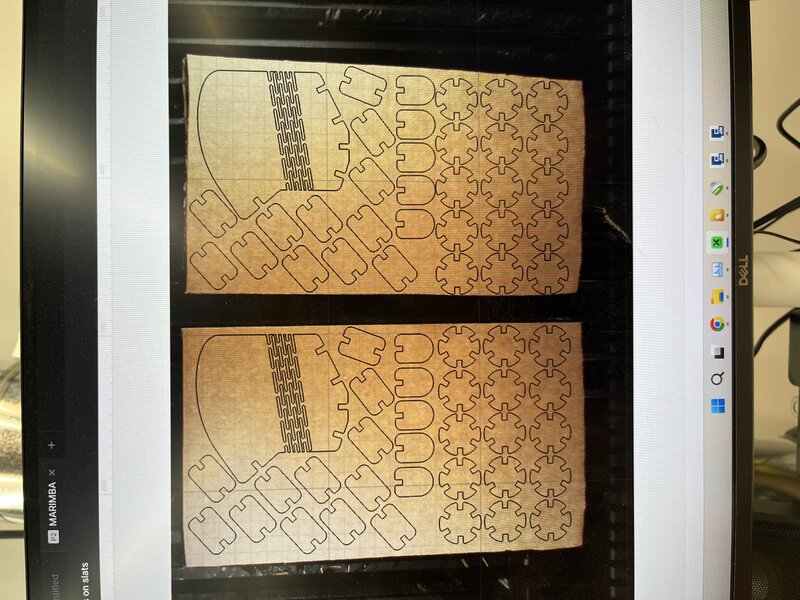
I laid out my .dxf files for printing on my last remaining bit of cardboard (I only used one sheet for this whole process!). I cut the cardboard into two pieces to reduce the bowing, but I still did the aimed measure anyways to avoid repeating my previous mistake.
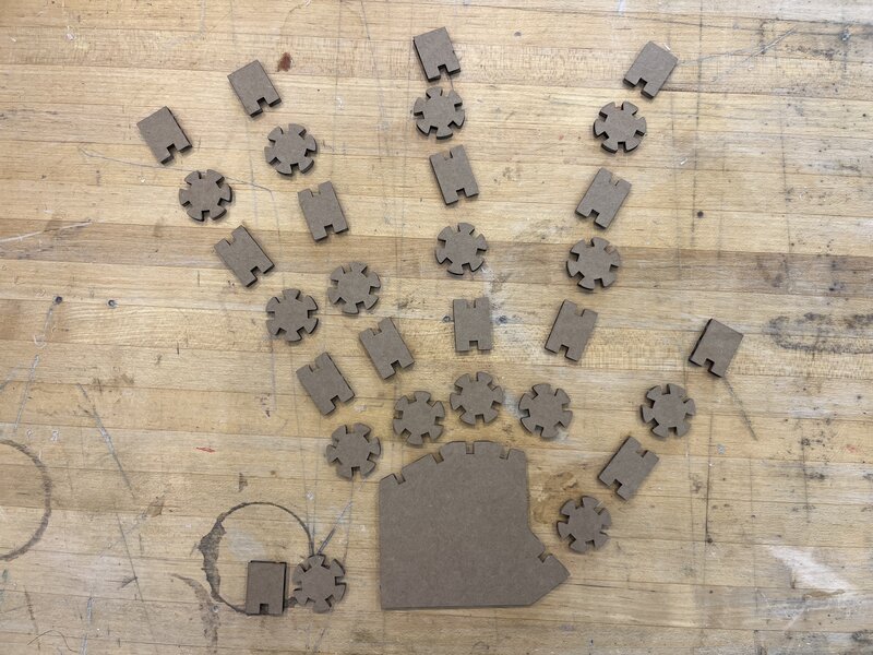
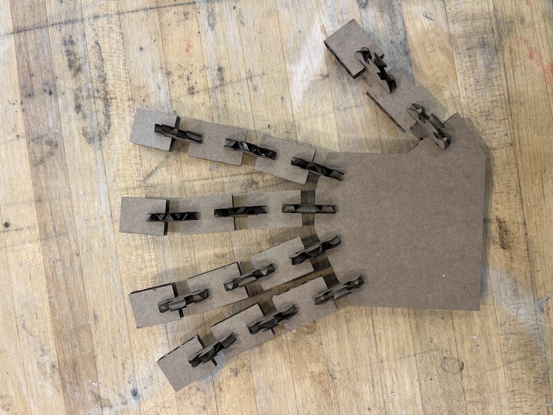
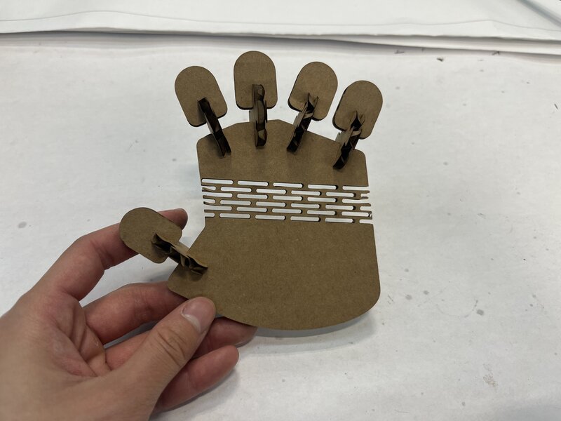
Finally, my weird idea came to life! Behold, hands:
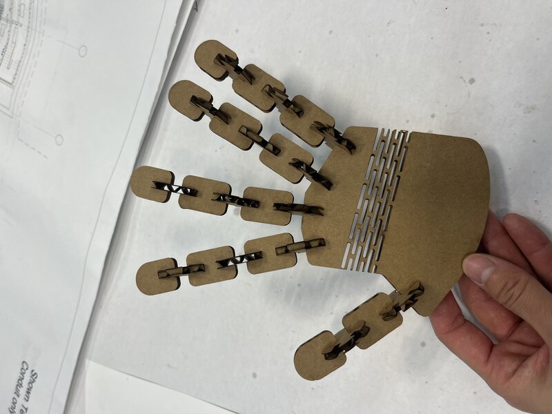
By slotting the phalanges into different slots on the joints, I could make poses, such as a peace sign:

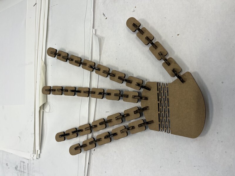
Behold, hnds:
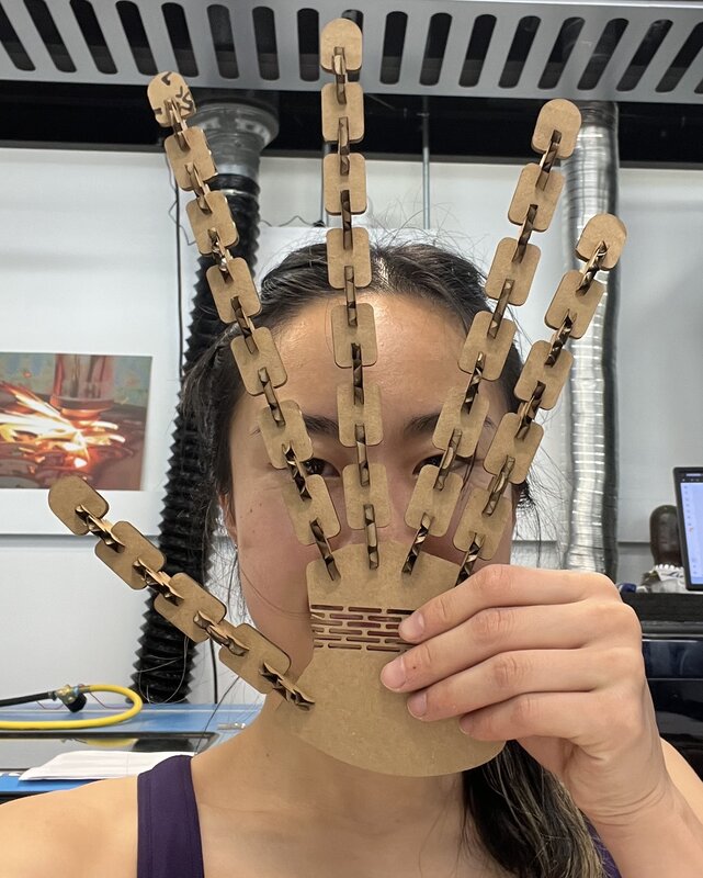
Behold, haaaaaaaaaaaaaaaaaands:
(My face, for scale)
After I finished this I realized it would have been fun to introduce flexure into the other joints as well. It wouldn’t be too hard to make a small piece with flexure with slots on both sides, but I decided to stop here.