Tiny DDR v0
I want to make a tiny Dance Dance Revolution machine. I am hoping to continue to develop this idea over the coming weeks, so this is by no means a finished product. For this week’s assignment I am merely dipping my toes into the world of embedded programming by scaffolding out some basic code that I can build on later. After spending 3.5 hours soldering all the components to my QPAD I was ready to begin the real journey.
Datasheet deep dive
First, I looked through the datasheet for the SAM D21 microcontroller I’m using. In particular I was looking to better understand how the microcontroller can be used to keep track of time (e.g., in milliseconds), as I anticipate I will need to use this to implement my game. In particular, the scoring for DDR is based on the number of milliseconds between the true timing of the beat and when the user pressed the correct arrow key, with narrower timing windows yielding higher scores.
I was a bit overwhelmed to discover a whole array of different clock-sounding modules: 14 Clock System, 15 GCLK - Generic Clock Controller, 30 TC – Timer/Counter, 19 RTC – Real-Time Counter, to name just a few. After a bit of AI-assisted investigation it seems like what I need is section 31, Timer/Counter for Control applications (TCC) peripheral. “The counter can be set to count events or clock pulses. The counter together with the compare/capture channels can be configured to time stamp input events…” Perfect!
Simulating Tiny DDR v0 with Wokwi
First, I adapted an existing Wokwi example to display an “up” arrow going from bottom to top of screen.
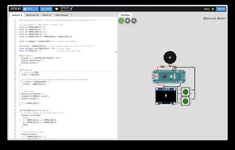
Regrettably, I accidentally deleted my git history of all of the following changes, but here were the features I implemented, in order: 1. added functionality to randomly generate up or down arrows from below the screen, and to use the same code as before to move the arrows from the bottom to the top of the screen. 2. implemented drawing of left / right arrows 3. made an Arrow struct which stores x, y, direction (up/down/left/right), a boolean for whether or not the arrow is active (visible on the screen) 4. initialized a fixed-size array of Arrows; added logic so that Arrow objects are marked inactive when they go off screen 5. made some tweaks and extended the arrow generation logic so arrows of all four directions are randomly generated and float from the bottom to the top of the screen; also distributed the arrows horizontally so they match the DDR layout a bit better (all left arrows in their own column on the left, then the column of down arrows, up, right)
I then added 2 more buttons to the Wokwi simulation to better mimic the layout of the QPAD. To visualize the button presses I updated my code to draw a rectangle at the bottom of the screen when a button of a certain direction is pressed. Here’s a video of that code in action:
Tiny DDR v0 on the QPAD
After installing the right board to my Arduino IDE and downloading the relevant libraries, I was able to get my prototype code running on the QPAD:
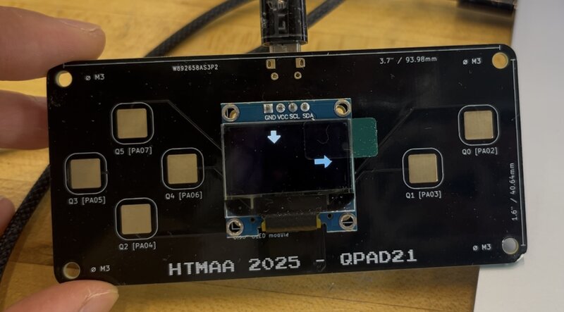
However, the button responses (the rectangles which were supposed to show up at the bottom of the screen) didn’t work! I thought this was because the pins were connected incorrectly (which they were) but the core issue is that the capacitive touch buttons don’t work quite as simply as the Wokwi-simulated button components – I found this helpful code snippet Quentin wrote and first uploaded it to my QPAD to verify I soldered properly. Then, I Frankensteined parts of that code snippet into my code to replace the button functionality with touch buttons – here is my updated code. I put this in a new branch because I will almost certainly not use capacitive touch buttons for the final version. Here’s a video of the same code I simulated, working properly with capacitive touch buttons: