Finally, the baby came out!!! I made it!!!
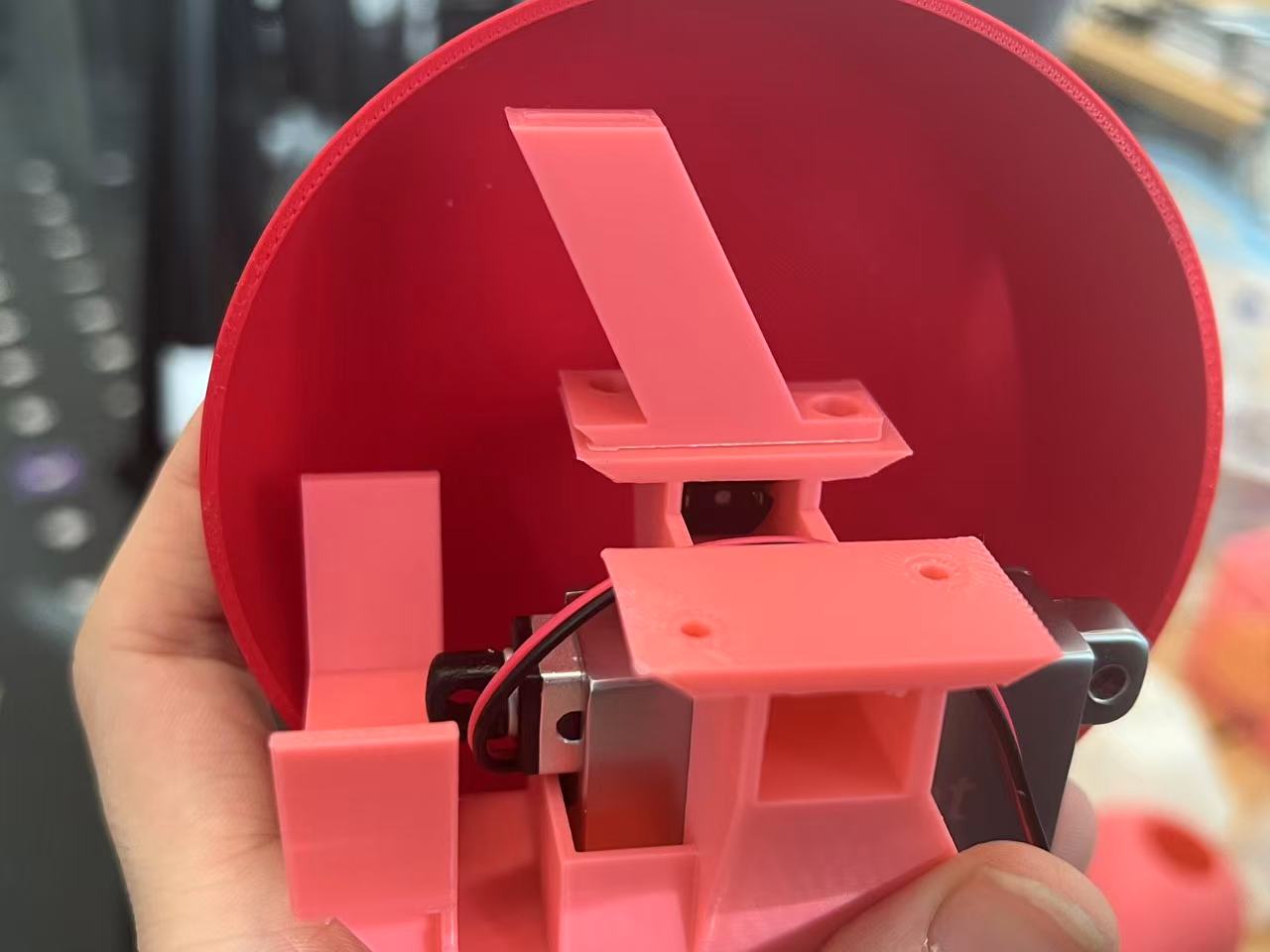
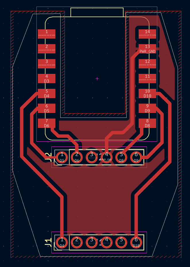
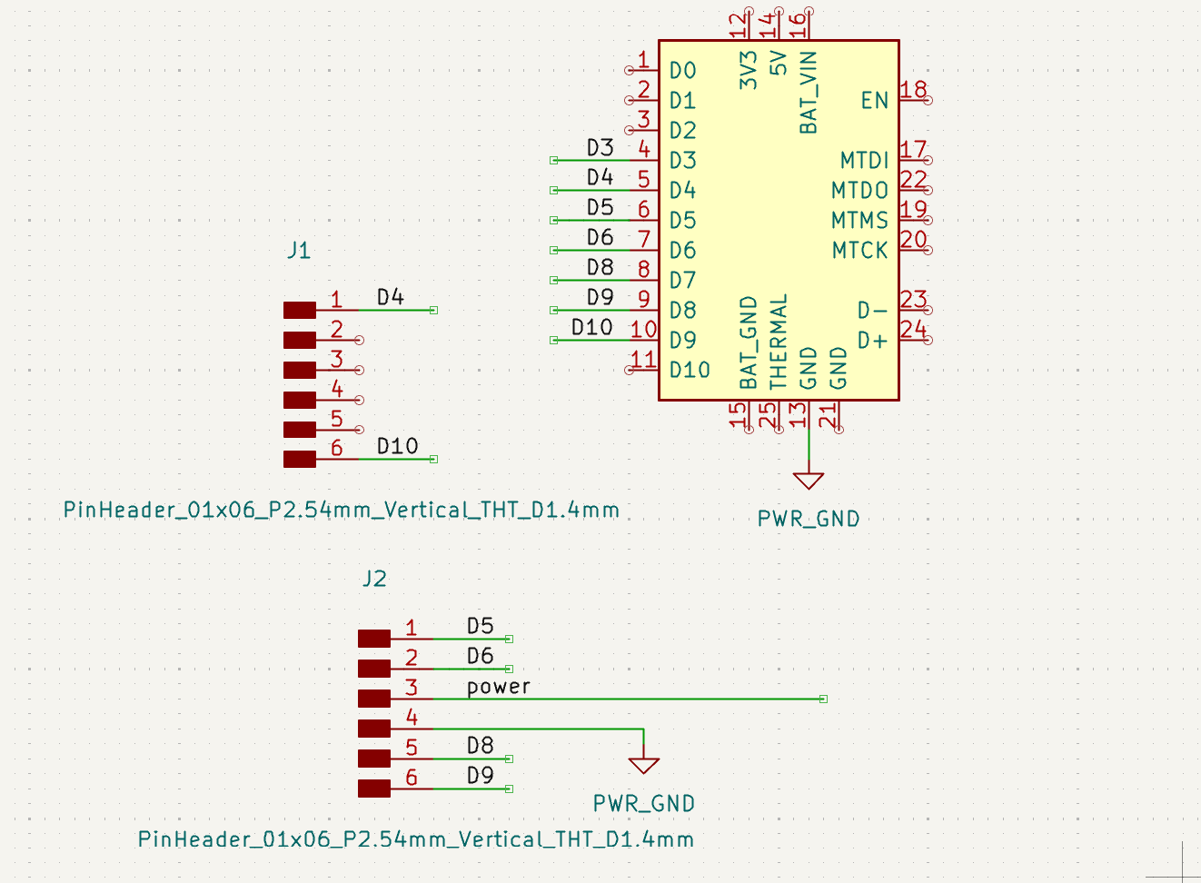
Here is the parent robot diagram showing how everything connects. It details the communication between the Commander and Receiver robots, the power distribution circuits, and how the water pumps and motors are integrated into the final design.
The birth of Robots
This is a pure art project so far, so don't ask me any practical use right now. I DUNNO! I try to think about the lives of robots by learning about the natural birth process.
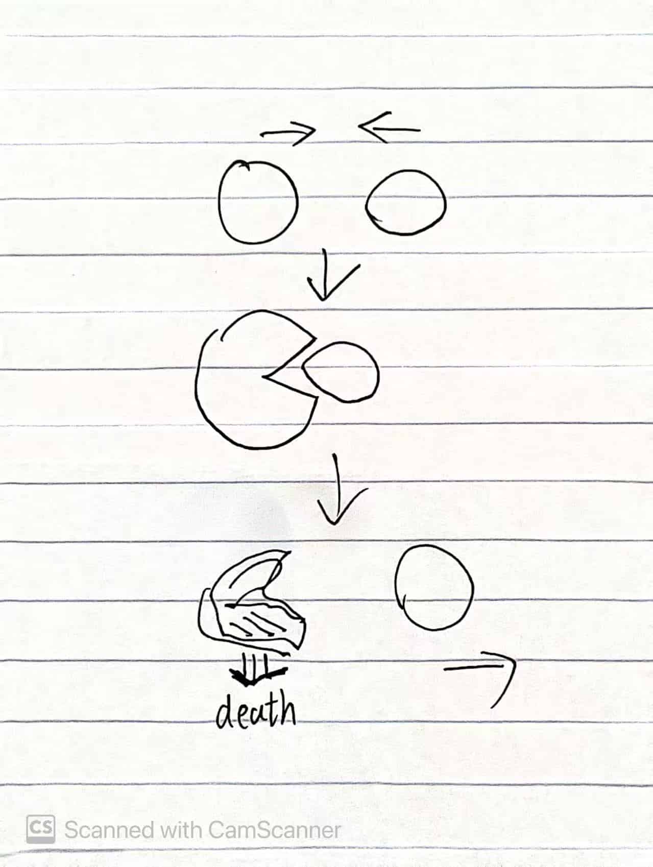
Right: Latest version where the parent robot stays alive after giving birth.
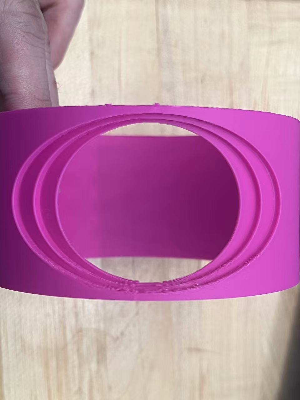
Previous Design
I initially aimed to explore multi-agent aquatic systems with sphere robots, creating water traces. However, similar existing projects led me to pivot towards simulating robot birth and death processes—a more personal and unique direction.
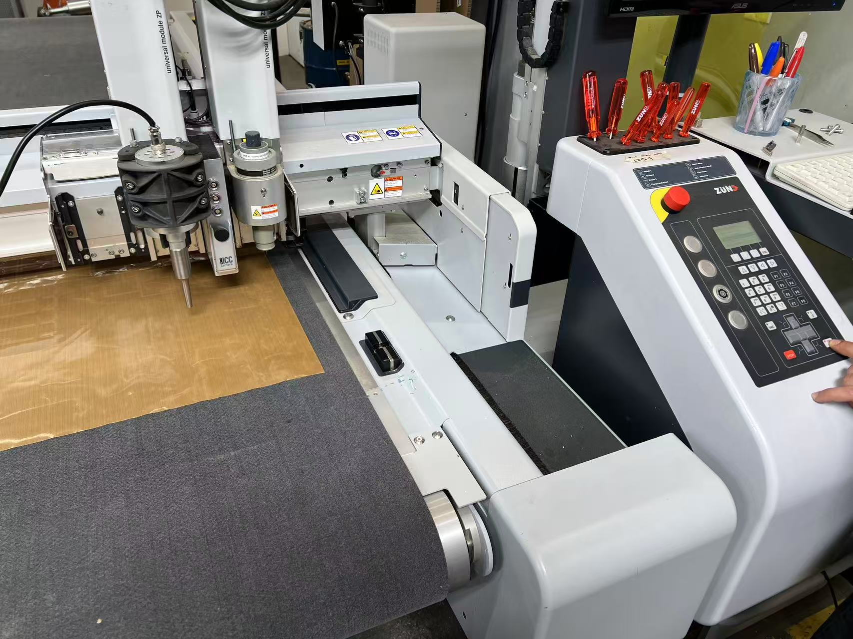
Preparation & System
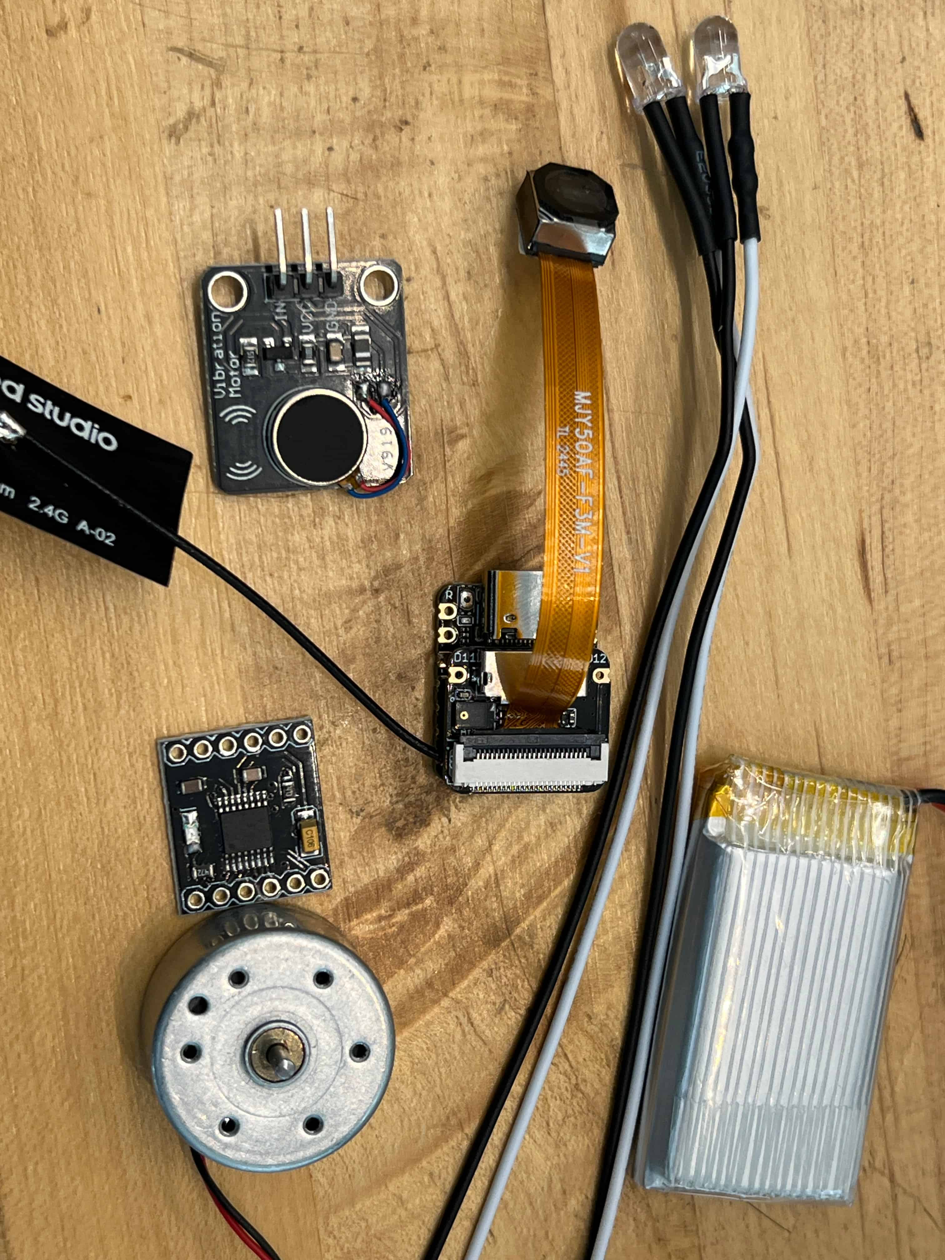
I prepared components (XIAO ESP32 S3, motors, batteries) and designed a custom PCB to fit the compact sphere mechanism. Early tests included a linear actuator for the birth push.
How to Push Baby Robot
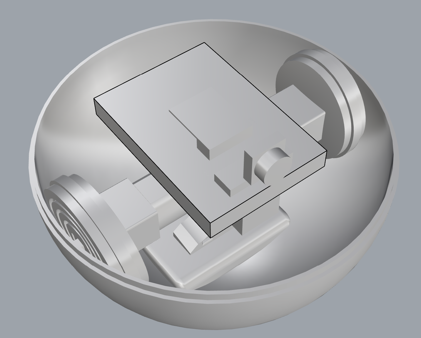
I explored a mechanical approach using a linear actuator to physically push the baby robot out. This prototype was largely completed and functional. The design featured wheels on the left and right sides for movement, creating a stable platform. The central mechanism used the linear actuator to push the small sphere (baby robot) out through an opening in the middle, without requiring any complex rotation of the body.
This is a testing video of the mechanism. The electronics here are very simple: I'm just using a Xiao microcontroller to control two basic DC motors directly.
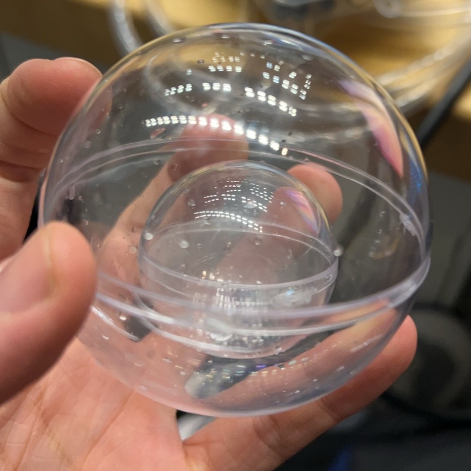
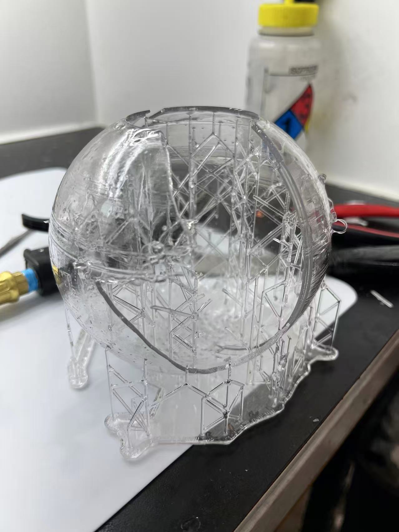
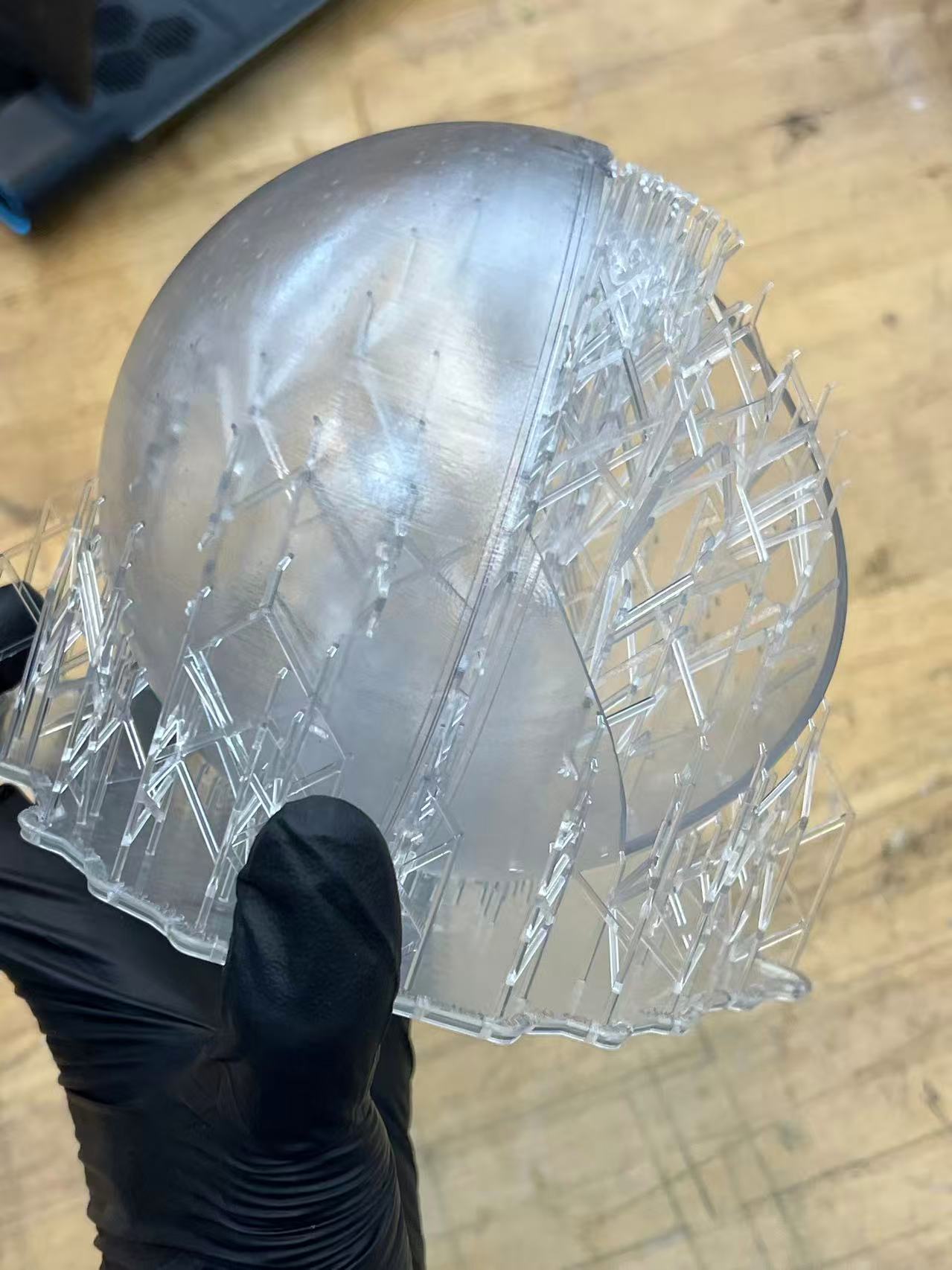
I also encountered failing cases with the shell fabrication. I attempted to print two separate transparent hemispheres using a Formlabs resin printer. Unfortunately, these prints failed completely, regardless of whether I oriented them upright or inverted, and despite the slicing software showing no errors.
Turning Point:
Change Direction Completely
While the linear actuator worked, I couldn't help but wonder: is there a more natural, organic, and interesting way to achieve this? I didn't want the robot to feel like a machine just ejecting a part. Later, I discovered a video demonstrating the use of pneumatics to control soft robot behaviors. This was a major inspiration for me, suggesting that air and inflation could be the key to a more biological-looking birth process.
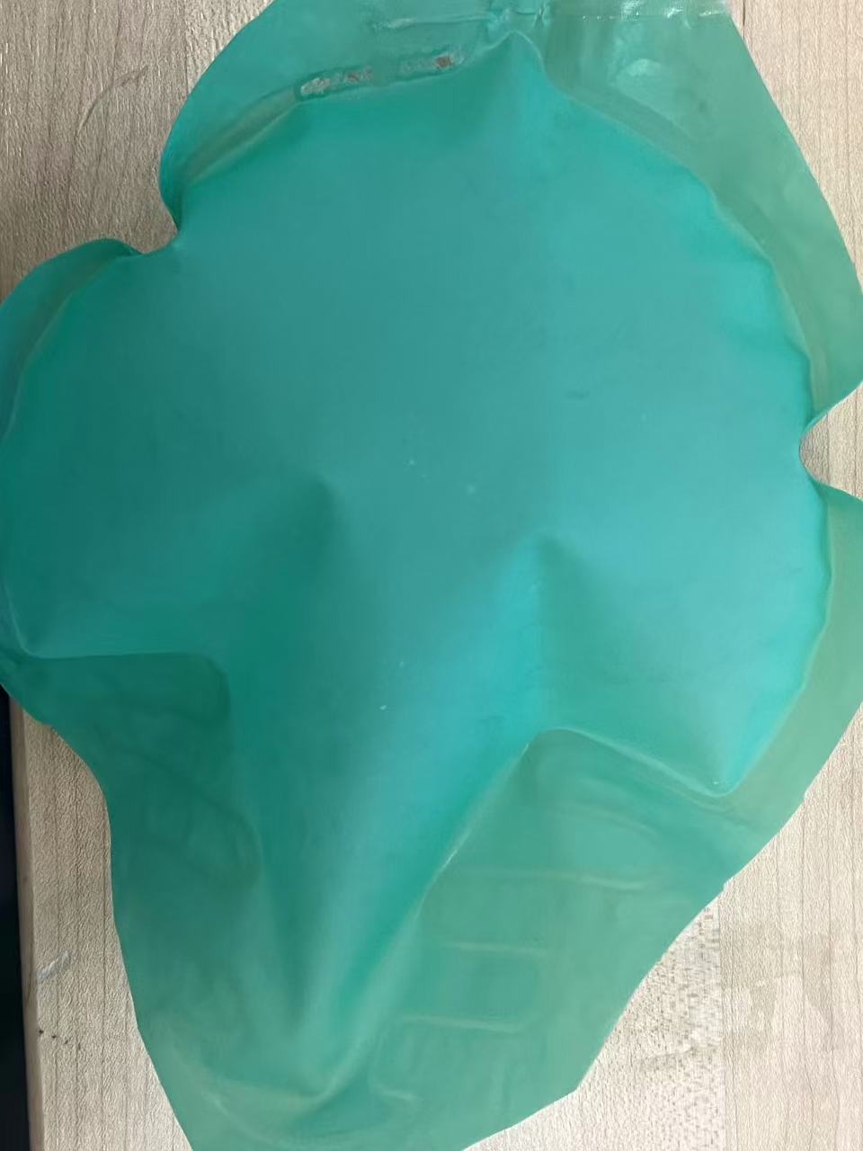
Inspired by this, I wanted to attempt using an inflatable structure to push the baby robot out. This approach aligns perfectly with my goal of creating a more organic and biological mechanism, reminiscent of actual birth processes. So, recalling my previous explorations in Week 15, I decided to revisit those techniques. With a "give it a try" attitude, I experimented with creating some 2D inflatable structures to see if they could generate the necessary pushing force.
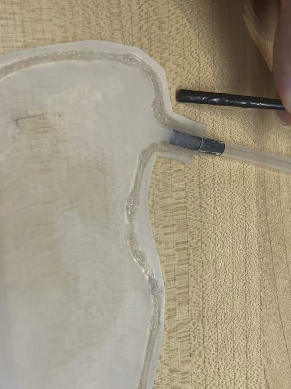
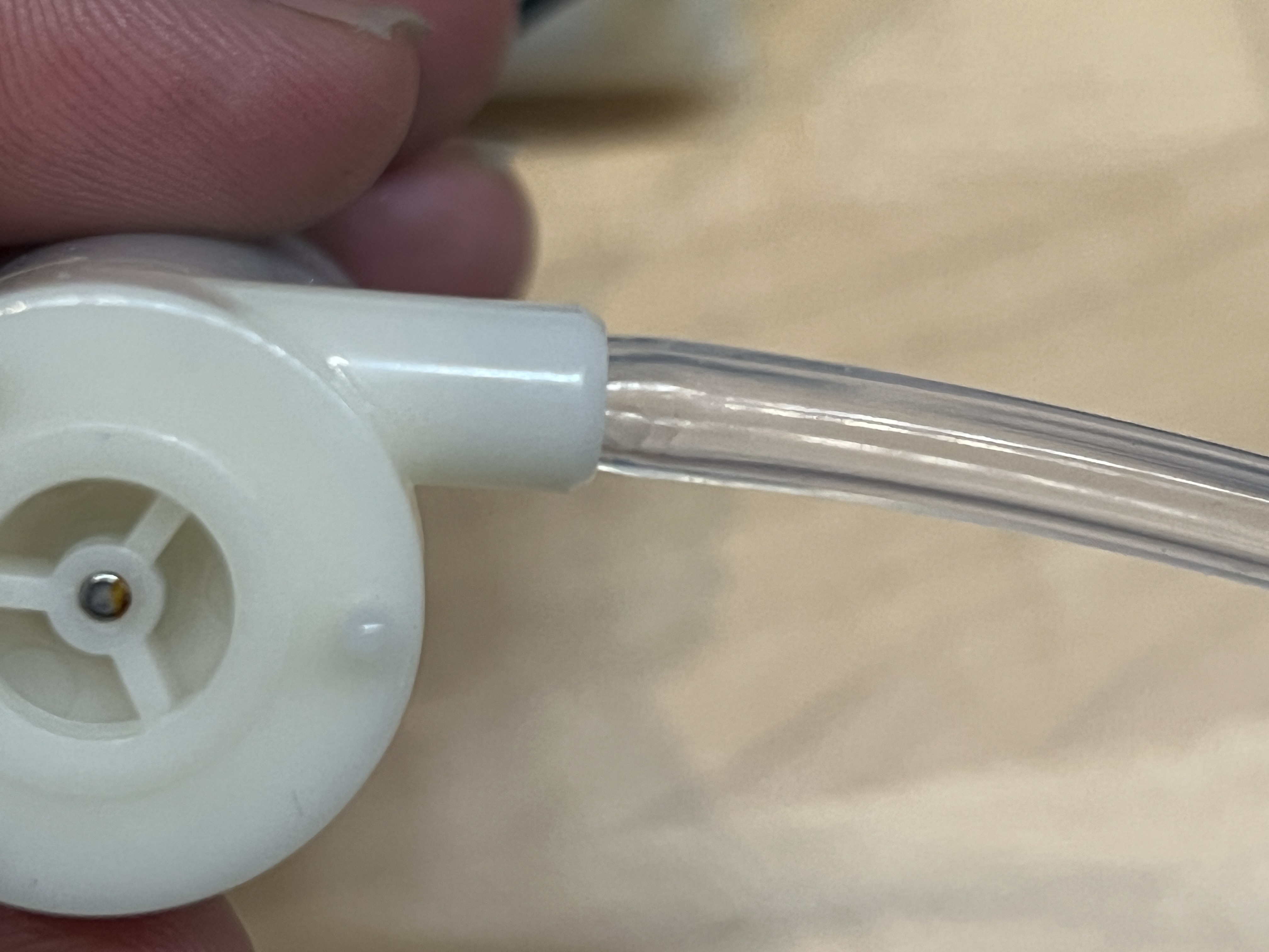
Initially, simply blowing air into the structure wasn't strong enough to push even slightly heavier objects. However, I remembered that I had purchased small water pumps. I realized I could connect a tube to the pump and pump water into the inflatable structure instead of air. I decided to test this by placing the inflatable mechanism inside my previous 3D-printed model and placing a small ball inside to see if it could be pushed out. The result was a success! The water pressure was sufficient to smoothly push the object out from the "belly" of the robot.
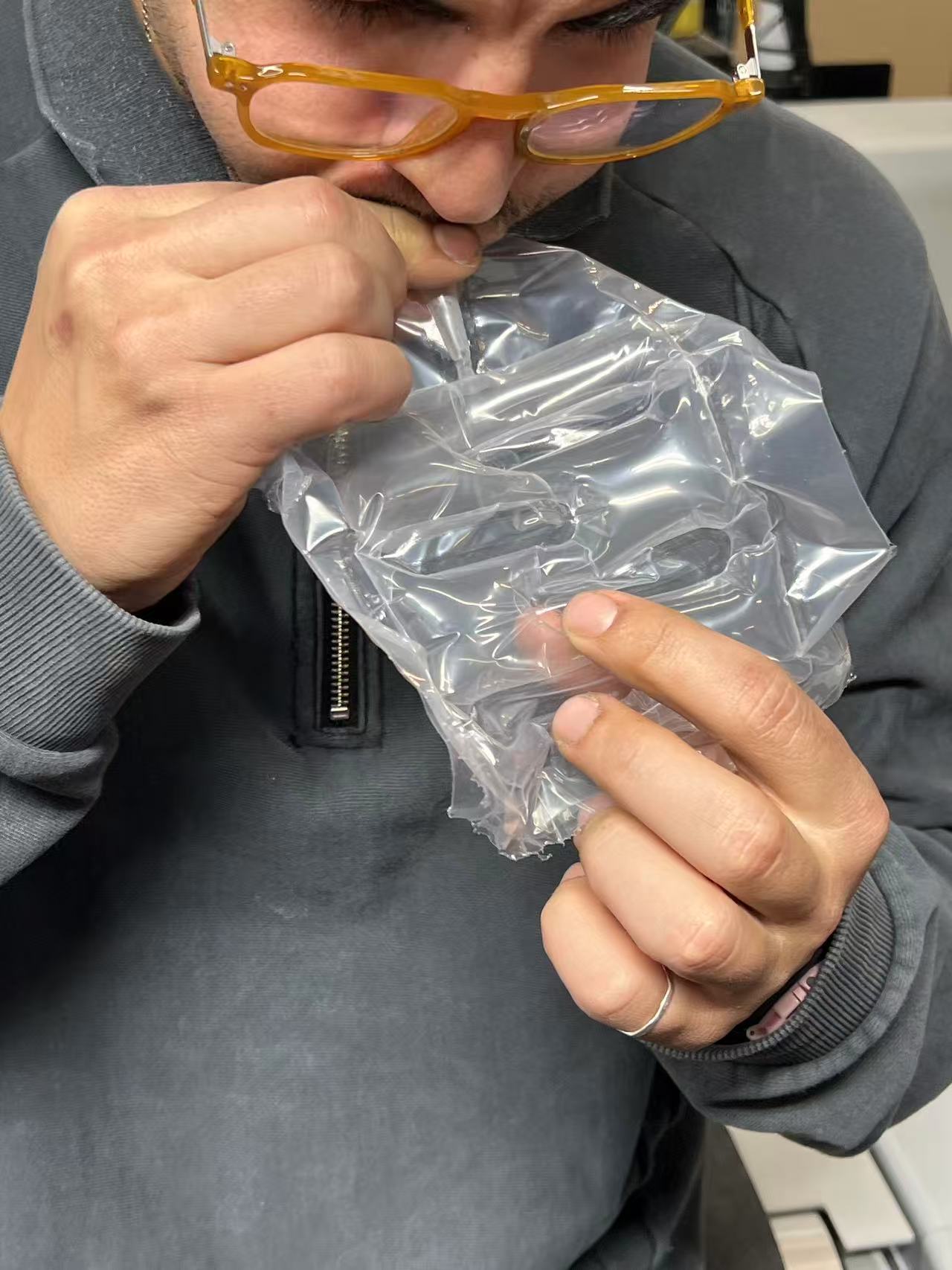
I experimented with various methods to connect the tube to the bubble, including using intermediate connectors, heat pressing, and direct insertion. Surprisingly, I discovered that the simplest method was the most effective for waterproofing: directly connecting the tube to the bubble. By using a tube slightly larger than the bubble's opening, the natural tension created a tight seal that effectively prevented leakage without needing complex bonding.
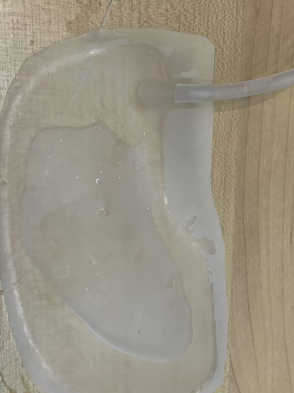
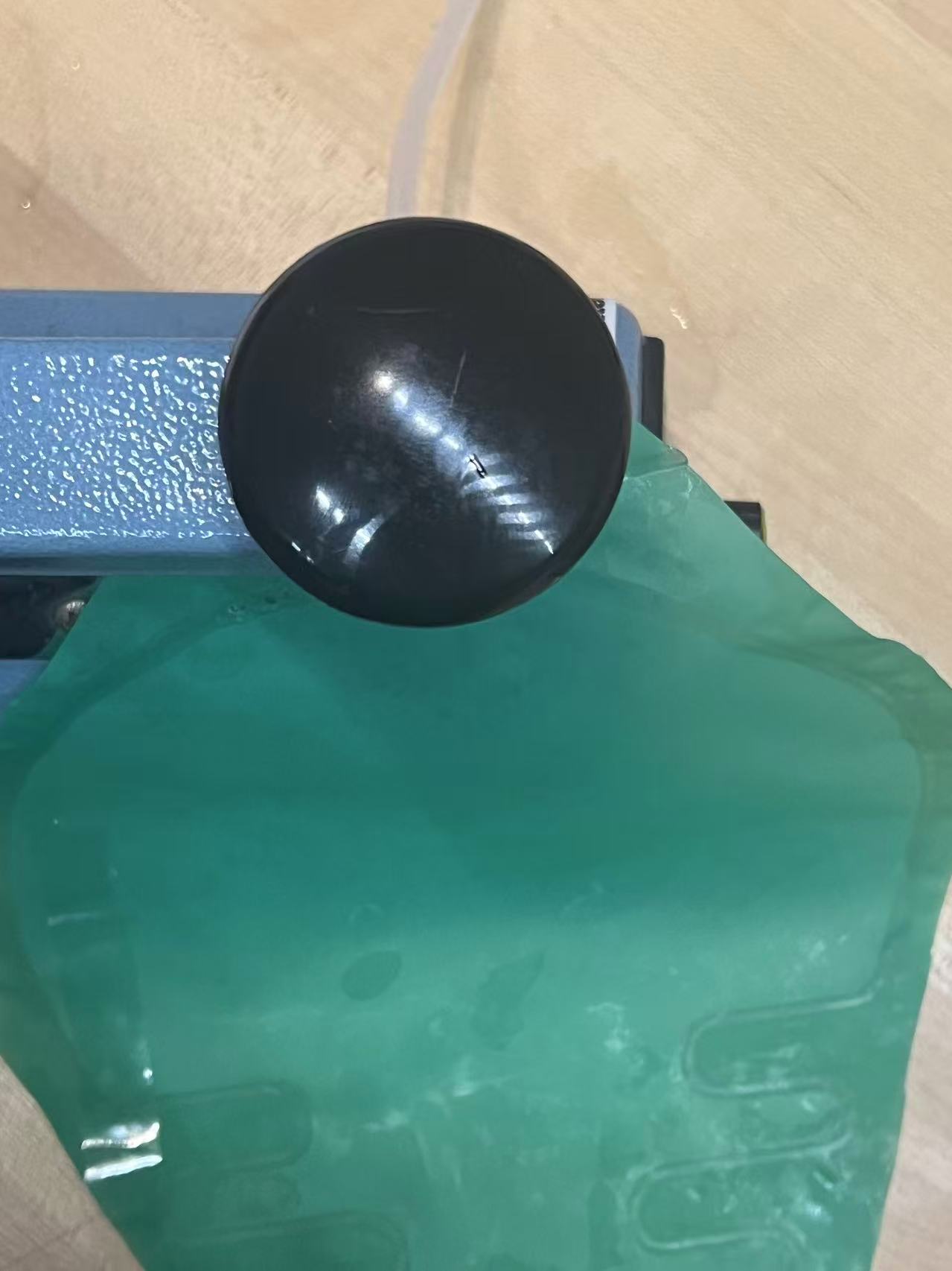
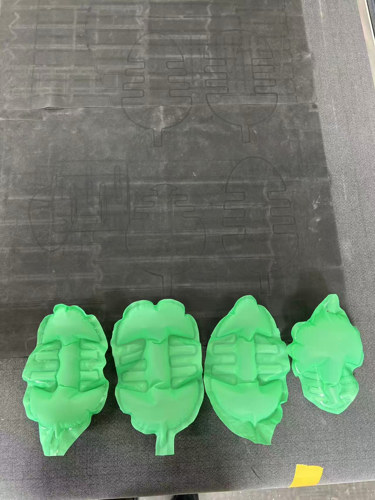
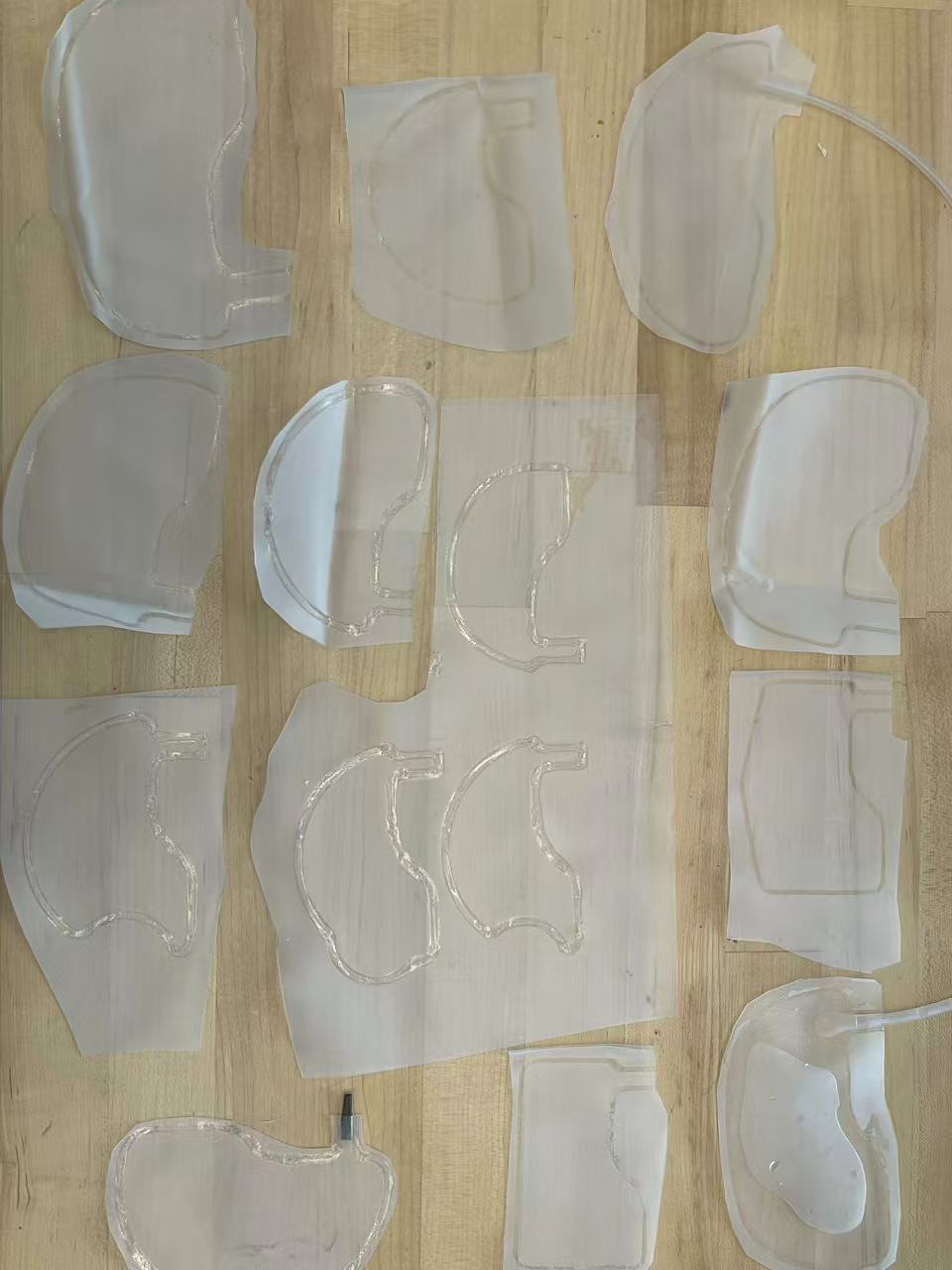
I also created inflatables of various sizes and shapes to test how different geometries affect the thrust force for later stages.
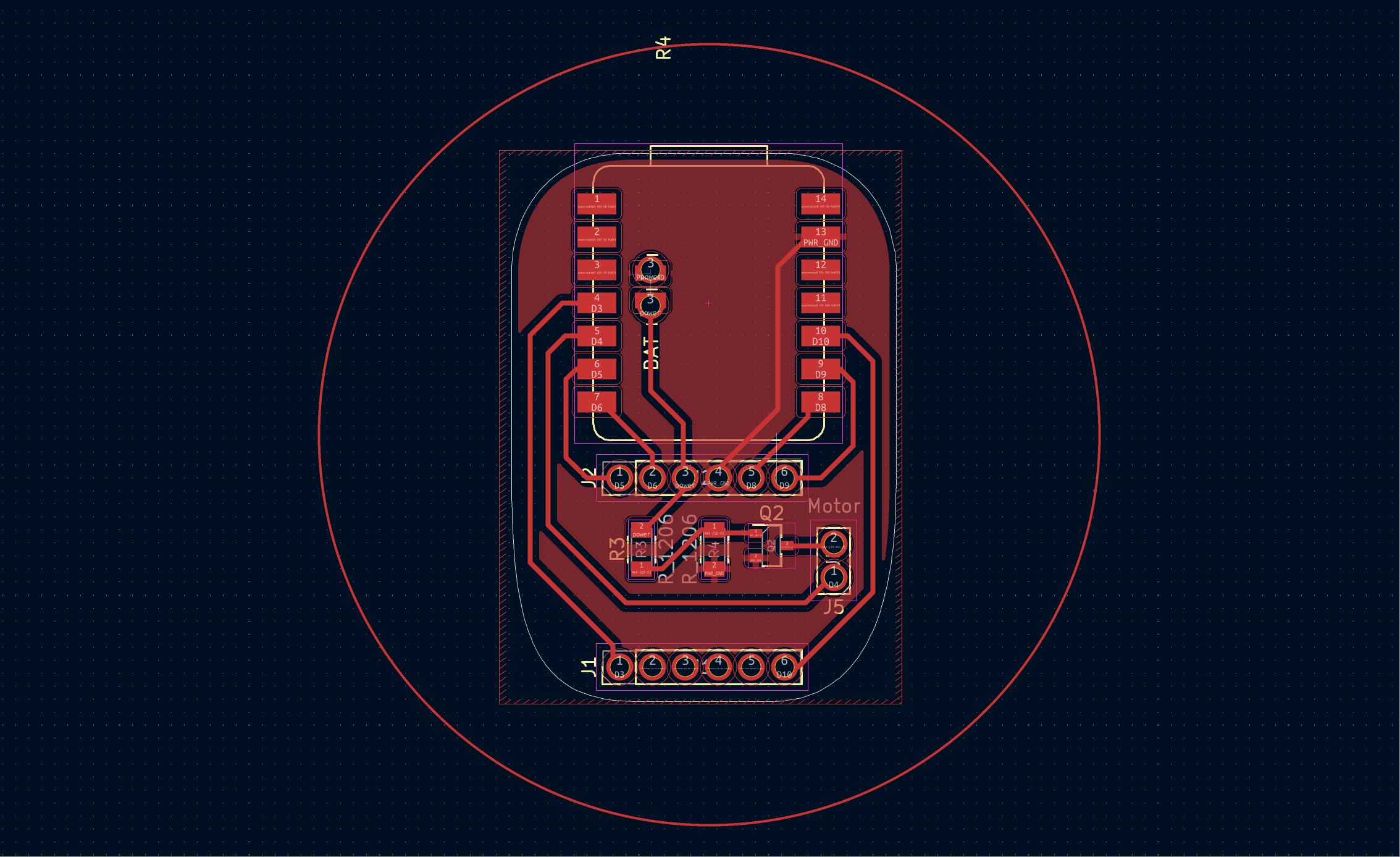
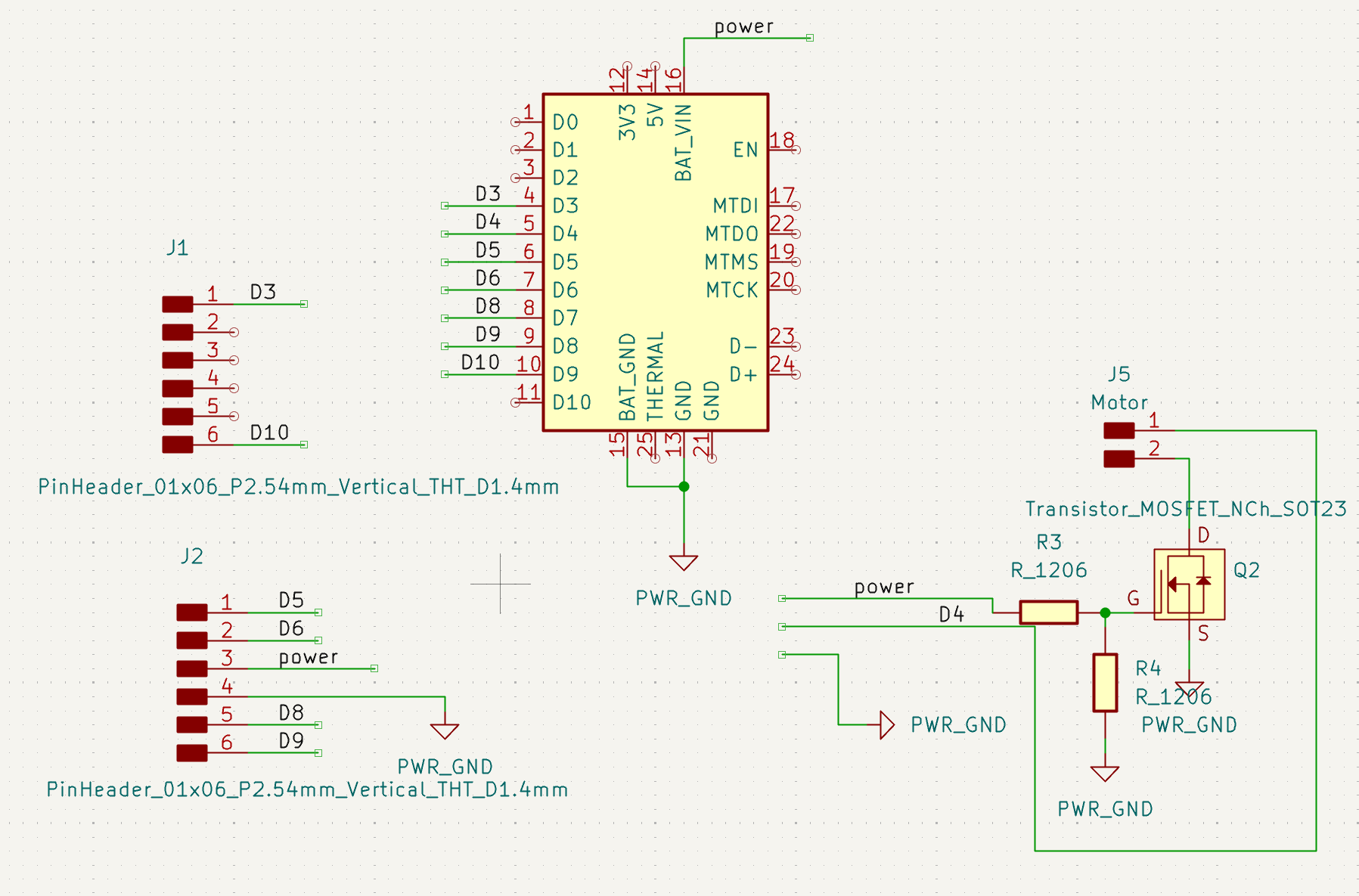
Electronic Design
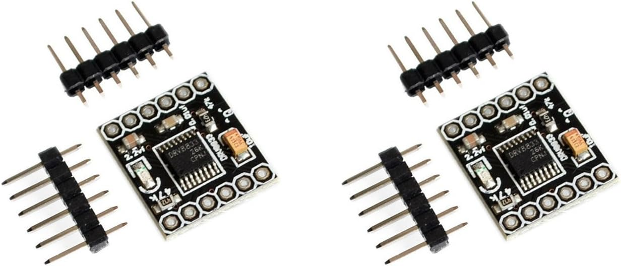
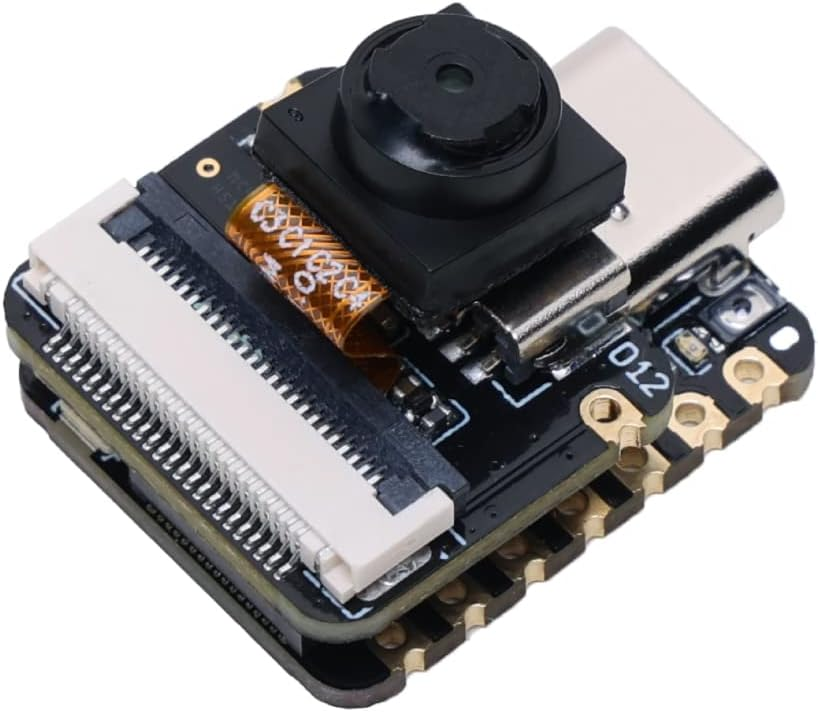
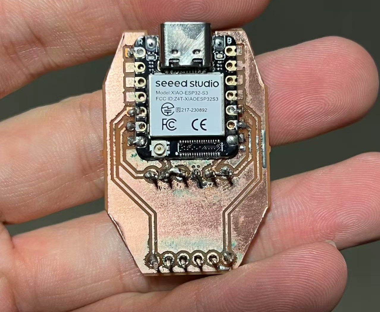
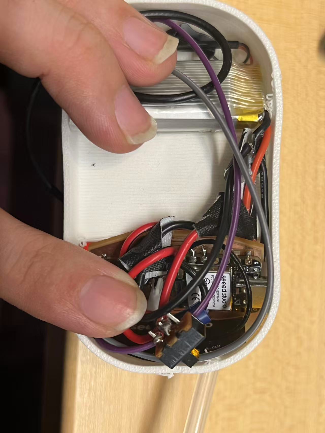
Given the complexity of the robot's shape and mechanism, I wanted to minimize potential bugs in the electronics. Applying the principle of Occam's Razor, I decided to simplify the design by removing all unnecessary components. The final setup consists only of a XIAO ESP32S3 and a DRV8833 1.5A 2-Channel DC Motor Drive Board, connected to a battery and a switch. I specifically chose the XIAO version with a camera interface, allowing the camera to function as a sensor. This approach significantly simplifies the EDA and reduces the likelihood of errors.
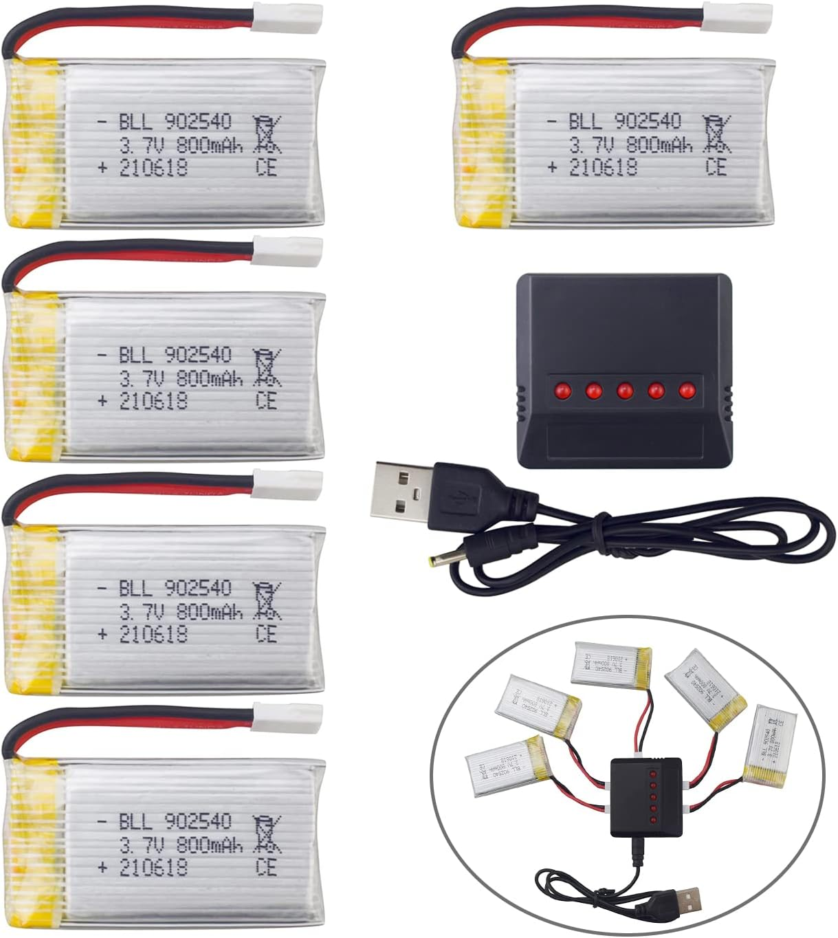
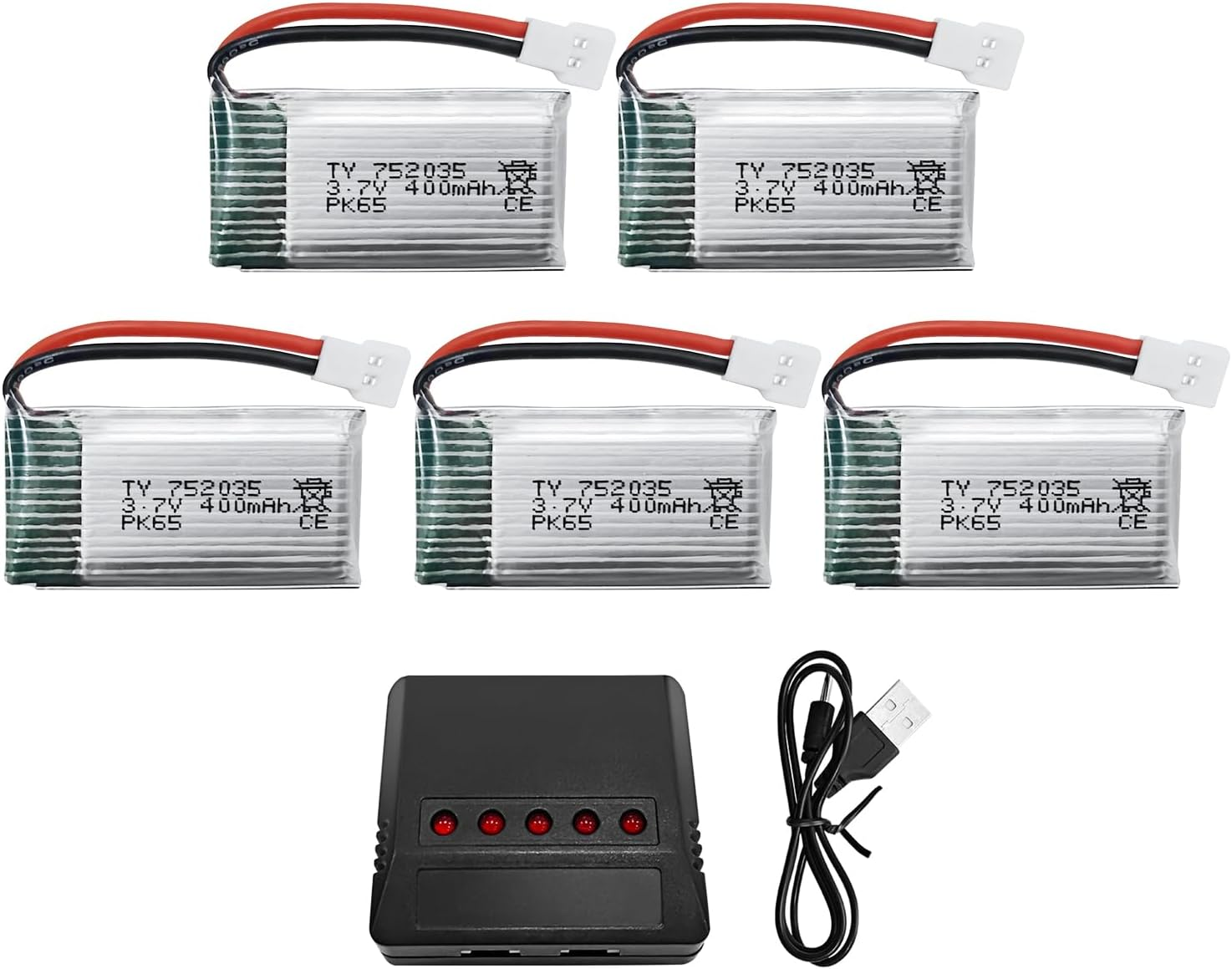
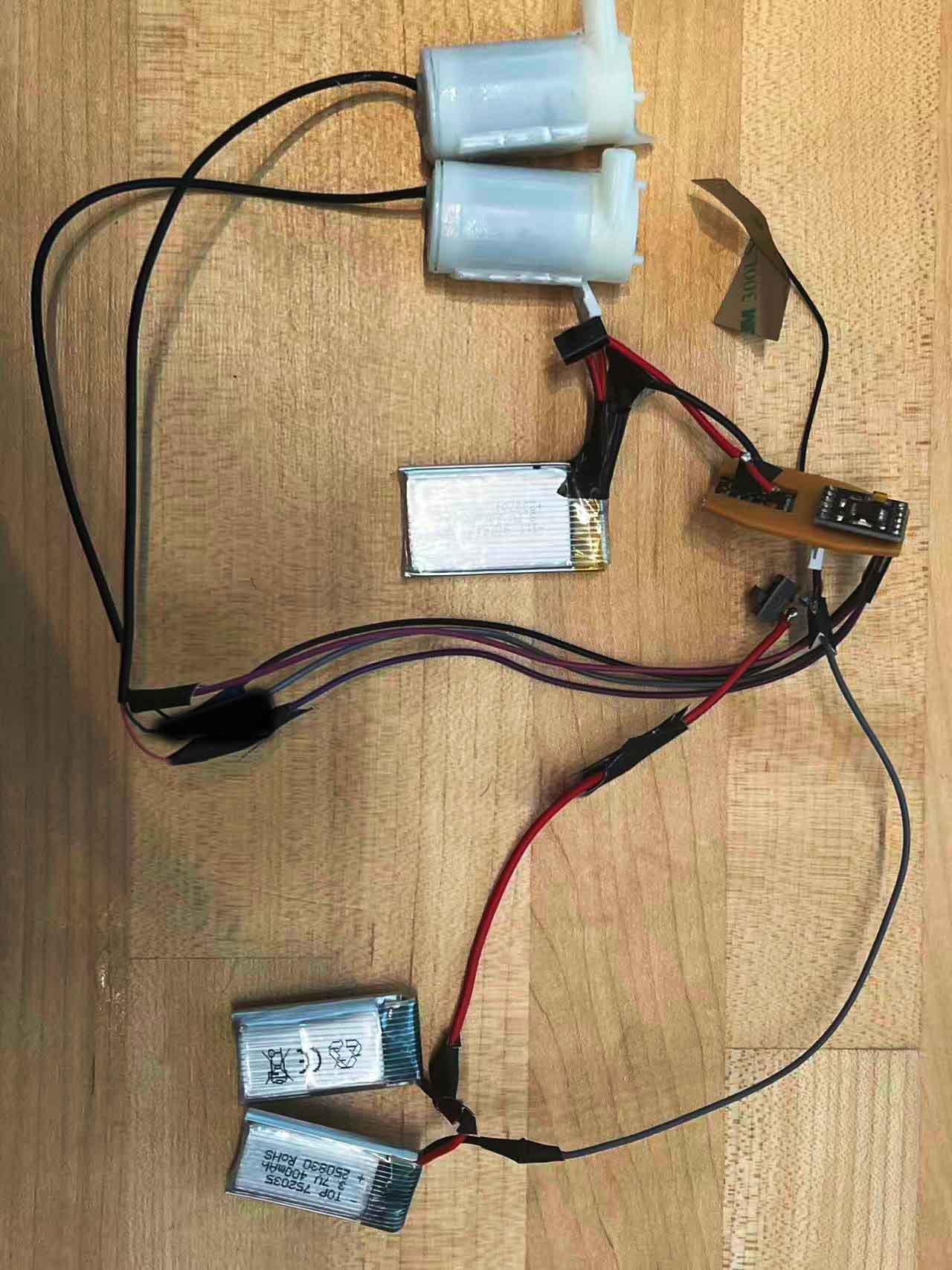
For the power supply, I chose two different 3.7V batteries. While they share the same voltage, the 400mAh battery offers a higher discharge rate, making it ideal for the DC motor which requires a larger instantaneous current. The 800mAh battery, with its larger capacity, is better suited for the XIAO microcontroller, providing better endurance for continuous operation.
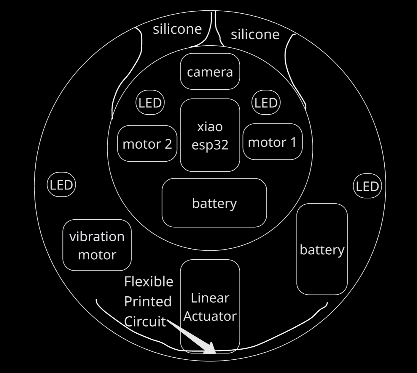
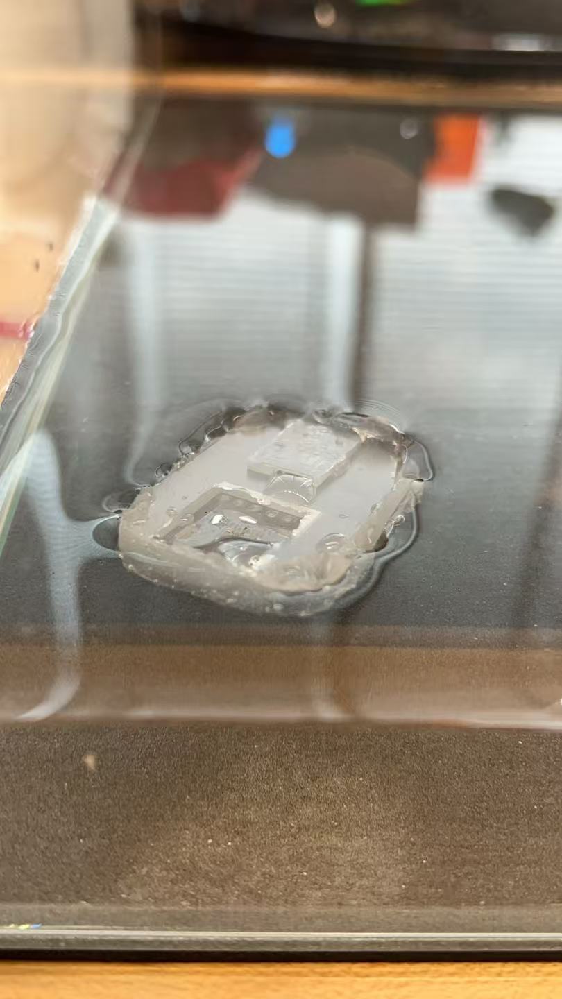
The fabricated PCB is extremely compact, making it well-suited for the mini robot. It routes power from the battery directly to the XIAO via a switch for easy control. The wiring connects to the positive and negative pads on the back of the XIAO; this specific requirement is the reason I designed the corresponding cutout in the housing structure.
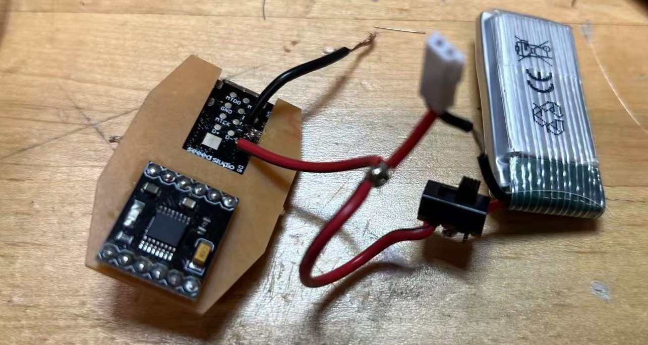
For the baby robot, due to the extremely limited internal space, I used a single small battery to power both the DC motor and the XIAO ESP32 simultaneously. I also incorporated a charging interface to ensure the battery could be easily recharged.
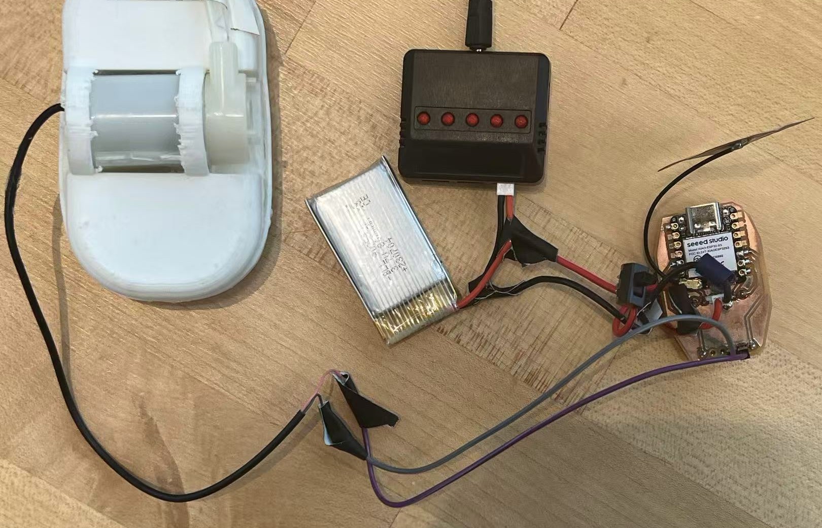
For the parent robot, the power requirements were more demanding. I used a dedicated 800mAh battery for the XIAO, as maintaining a stable WiFi connection consumes significant power. For the two DC water pumps, I connected two 400mAh 3.7V batteries in series to provide a higher voltage (7.4V), ensuring sufficient power and even allowing for some overclocking. The XIAO and the motor driver share a common ground reference.
Bill of Materials
What I Buy
- DRV8833 Motor Driver (x2)
- 3.7V LiPo Battery (400mAh & 800mAh)
- Slide Switches
- Mini DC Water Pumps
- DC Motors (Small)
- Silicone / Vinyl Tubing
What I Use from CBA Lab
- Seeed Studio XIAO ESP32S3 (x2)
- Inflatable Material (TPU)
- PCB Copper Board (FR1)
- 3D Printing Resin / Filament (PLA/Tough 2000)
- Wires & Heat Shrink
- Pin Headers (2.54mm)
- Solder
- Equipment Access (Roland Mill, Formlabs, Prusa)
Network
Connect WiFi and Controlled with Phone
Both robots are connected to the same "MLDEV" WiFi network. The system has two main parts:
🤖 ROBOT 1: The Commander (Parent Robot)
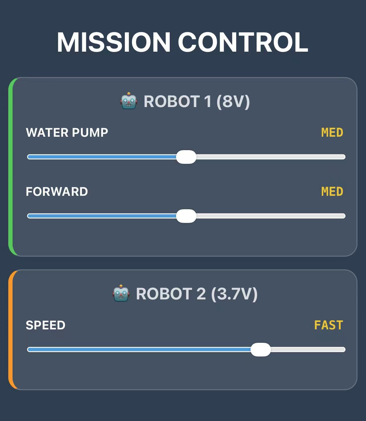
This robot acts as the boss. It creates a simple website that I can open on my phone to control everything.
How the Code Works:
- Control Panel: The robot hosts a webpage with sliders. When I move a slider on my phone, it instantly sends the new speed to the robot.
- Voltage Protection: My 8V battery is actually too strong for the 6V motors. To keep them safe, the code limits the maximum power to about 75%. Even if I go "Turbo," it holds back a bit to prevent burning out the motors.
- Remote Control: When I want to move Robot 2 (the baby), Robot 1 acts like a messenger. It takes my command and passes it over WiFi to Robot 2.
- Staying Awake: The motor driver tends to fall asleep if it's inactive for too long. The code keeps sending a tiny, invisible signal just to say "stay awake!"
Code: Robot 1 (Commander)
/*
 * ROBOT 1: COMMANDER NODE
 * Battery: 7.4V - 8V (Requires Voltage Limiting)
 * IP Address: 192.168.41.251
 * Function: Controls internal motors and sends commands to Robot 2 via HTTP.
 */

#include <WiFi.h>
#include <WebServer.h>

// --- Pin Definitions ---
const int IN1 = D5;
const int IN2 = D6;
const int IN3 = D7;
const int IN4 = D8;
const int SLEEP_PIN = D9;
const int FAULT = D4;

// --- Wi-Fi Credentials ---
const char* ssid = "MLDEV";
const char* password = "Aysyw2ch?";

// --- Static IP Configuration (.251) ---
IPAddress local_IP(192, 168, 41, 251);
IPAddress gateway(192, 168, 41, 1);
IPAddress subnet(255, 255, 255, 0);
IPAddress primaryDNS(18, 27, 72, 81);

WebServer server(80);

// --- PWM Settings ---
const int freq = 30000;
const int resolution = 8;

// --- Web Interface (Stored in Flash Memory) ---
const char index_html[] PROGMEM = R"rawliteral(
<!DOCTYPE html>
<html lang="en">
<head>
  <meta charset="UTF-8">
  <meta name="viewport" content="width=device-width, initial-scale=1">
  <title>Mission Control</title>
  <style>
    body { font-family: -apple-system, sans-serif; text-align: center; background: #2c3e50; color: white; padding: 10px; margin: 0;}
    h2 { margin-top: 0; font-size: 1.2rem; opacity: 0.8; }

    /* Card Styles */
    .robot-box {
      background: rgba(255,255,255,0.1);
      border-radius: 15px; padding: 15px; margin: 15px auto;
      max-width: 400px; border: 1px solid rgba(255,255,255,0.2);
    }
    .robot-1 { border-left: 5px solid #34c759; } /* Green for Robot 1 */
    .robot-2 { border-left: 5px solid #ff9500; } /* Orange for Robot 2 */

    .control-group { margin-bottom: 15px; }
    .label { display: flex; justify-content: space-between; font-weight: bold; font-size: 0.9rem; margin-bottom: 5px;}
    input[type=range] { width: 100%; height: 25px; accent-color: #3498db; }

    .status { font-family: monospace; font-weight: bold; color: #f1c40f; }
  </style>
</head>
<body>

  <h1>MISSION CONTROL</h1>

  <div class="robot-box robot-1">
    <h2>🤖 ROBOT 1 (8V)</h2>
    <div class="control-group">
      <div class="label"><span>WATER PUMP</span> <span id="r1_pump_txt" class="status">STOP</span></div>
      <input type="range" min="0" max="4" value="0" oninput="cmd(1, 'pump', this.value)">
    </div>
    <div class="control-group">
      <div class="label"><span>FORWARD</span> <span id="r1_move_txt" class="status">STOP</span></div>
      <input type="range" min="0" max="4" value="0" oninput="cmd(1, 'move', this.value)">
    </div>
  </div>

  <div class="robot-box robot-2">
    <h2>🤖 ROBOT 2 (3.7V)</h2>
    <div class="control-group">
      <div class="label"><span>SPEED</span> <span id="r2_speed_txt" class="status">STOP</span></div>
      <input type="range" min="0" max="4" value="0" oninput="cmd(2, 'speed', this.value)">
    </div>
  </div>

  <script>
    const gears = ["STOP", "SLOW", "MED", "FAST", "TURBO"];
    const ip2 = "http://192.168.41.252"; // Robot 2 IP

    function cmd(robot, type, val) {
      val = parseInt(val);

      // Update UI Text
      let id = "";
      if(robot === 1 && type === 'pump') id = "r1_pump_txt";
      if(robot === 1 && type === 'move') id = "r1_move_txt";
      if(robot === 2) id = "r2_speed_txt";
      document.getElementById(id).innerText = gears[val];

      // Send Command
      let url = "";
      if (robot === 1) {
        // Control Self
        url = "/set?motor=" + type + "&val=" + val;
      } else {
        // Control Robot 2 (Cross-Origin Request)
        url = ip2 + "/set?val=" + val;
      }

      // Send non-blocking request
      fetch(url).catch(err => console.log("Error:", err));
    }
  </script>
</body>
</html>
)rawliteral";

void handleRoot() { server.send(200, "text/html", index_html); }

void handleSet() {
  // Add CORS header just in case
  server.sendHeader("Access-Control-Allow-Origin", "*");

  if (server.hasArg("motor") && server.hasArg("val")) {
    String motor = server.arg("motor");
    int val = server.arg("val").toInt();
    int pwmValue = 0;

    // --- LOGIC: 8V Protection & Anti-Sleep ---
    switch(val) {
      case 0: pwmValue = 1; break;   // CRITICAL: Send 1 instead of 0 to keep driver awake
      case 1: pwmValue = 110; break;
      case 2: pwmValue = 140; break;
      case 3: pwmValue = 170; break;
      case 4: pwmValue = 195; break; // SAFETY: Limit to 195 (approx 6V) to prevent Brownout
      default: pwmValue = 1;
    }

    if (motor == "pump") {
      ledcWrite(IN1, pwmValue);
    } else if (motor == "move") {
      ledcWrite(IN3, pwmValue);
    }
    server.send(200, "text/plain", "OK");
  } else { server.send(400, "text/plain", "Bad Request"); }
}

void setup() {
  Serial.begin(115200);
  pinMode(IN1, OUTPUT); pinMode(IN2, OUTPUT);
  pinMode(IN3, OUTPUT); pinMode(IN4, OUTPUT);
  pinMode(SLEEP_PIN, OUTPUT); pinMode(FAULT, INPUT_PULLUP);
  pinMode(LED_BUILTIN, OUTPUT);

  // Initialize Pins
  digitalWrite(IN2, LOW);
  digitalWrite(IN4, LOW);
  digitalWrite(SLEEP_PIN, HIGH); // Wake up driver

  // Initialize PWM (Start at 1 to prevent sleep)
  ledcAttach(IN1, freq, resolution);
  ledcAttach(IN3, freq, resolution);
  ledcWrite(IN1, 1);
  ledcWrite(IN3, 1);

  // Network Setup
  WiFi.config(local_IP, gateway, subnet, primaryDNS);
  WiFi.begin(ssid, password);

  // LED Logic: Blink while connecting
  while (WiFi.status() != WL_CONNECTED) {
    digitalWrite(LED_BUILTIN, !digitalRead(LED_BUILTIN));
    delay(200);
  }

  // LED Logic: Solid ON when connected (Low = On for XIAO)
  digitalWrite(LED_BUILTIN, LOW);

  server.on("/", handleRoot);
  server.on("/set", handleSet);
  server.begin();
}

void loop() {
  server.handleClient();

  // Watchdog: Force SLEEP_PIN HIGH constantly
  digitalWrite(SLEEP_PIN, HIGH);
  delay(2);
}
🤖 ROBOT 2: The Receiver (Baby Robot)
This robot basically listens to whatever Robot 1 says.
How the Code Works:
- Permission to Talk (CORS): Web browsers are strict; they usually block websites from sending commands to different devices. The "CORS" code is just a way of telling the browser, "It's okay, let Robot 1 talk to me."
- Full Power: Since this robot runs on a smaller battery, it needs all the juice it can get. Unlike Robot 1, I let the motors run at 100% power here to make sure they have enough strength to push the water.
- Simple Instructions: It doesn't "think" much. It just waits for a speed number (like 1, 2, 3...) and immediately sets the motor to that speed.
Code: Robot 2 (Receiver)
/*
 * ROBOT 2: RECEIVER NODE
 * Battery: 3.7V (Max Power Allowed)
 * IP Address: 192.168.41.252
 * Function: Receives commands via HTTP, allows Cross-Origin requests.
 */

#include <WiFi.h>
#include <WebServer.h>

// --- Pin Definitions ---
const int IN1 = D5; const int IN2 = D6;
const int IN3 = D7; const int IN4 = D8;
const int SLEEP_PIN = D9;
const int FAULT = D4;

// --- Wi-Fi Credentials ---
const char* ssid = "MLDEV";
const char* password = "Aysyw2ch?";

// --- Static IP Configuration (.252) ---
IPAddress local_IP(192, 168, 41, 252);
IPAddress gateway(192, 168, 41, 1);
IPAddress subnet(255, 255, 255, 0);
IPAddress primaryDNS(18, 27, 72, 81);

WebServer server(80);

const int freq = 30000;
const int resolution = 8;

void handleSet() {
  // --- CRITICAL: CORS Header ---
  // Allows Robot 1 (at .251) to control this robot
  server.sendHeader("Access-Control-Allow-Origin", "*");

  if (server.hasArg("val")) {
    int val = server.arg("val").toInt();
    int pwm = 0;

    // --- LOGIC: 3.7V Power Mapping ---
    // Since voltage is low, we need higher PWM values to move
    switch(val) {
      case 0: pwm = 1;   break; // Anti-Sleep (Keep signal alive)
      case 1: pwm = 150; break; // SLOW (Needs high PWM to start)
      case 2: pwm = 185; break; // MED
      case 3: pwm = 220; break; // FAST
      case 4: pwm = 255; break; // MAX (Full 3.7V power)
      default: pwm = 1;
    }

    // drive both ports synchronously
    ledcWrite(IN1, pwm);
    ledcWrite(IN3, pwm);

    server.send(200, "text/plain", "OK");
  } else {
    server.send(400, "text/plain", "Bad Request");
  }
}

void setup() {
  Serial.begin(115200);
  pinMode(IN1, OUTPUT); pinMode(IN2, OUTPUT);
  pinMode(IN3, OUTPUT); pinMode(IN4, OUTPUT);
  pinMode(SLEEP_PIN, OUTPUT); pinMode(FAULT, INPUT_PULLUP);
  pinMode(LED_BUILTIN, OUTPUT); // Yellow LED

  // Initialize Pins
  digitalWrite(IN2, LOW);
  digitalWrite(IN4, LOW);
  digitalWrite(SLEEP_PIN, HIGH); // Wake up driver

  // Initialize PWM
  ledcAttach(IN1, freq, resolution);
  ledcAttach(IN3, freq, resolution);
  ledcWrite(IN1, 1);
  ledcWrite(IN3, 1);

  // Network Setup
  WiFi.config(local_IP, gateway, subnet, primaryDNS);
  WiFi.begin(ssid, password);

  // LED Logic: Blink while connecting
  while (WiFi.status() != WL_CONNECTED) {
    digitalWrite(LED_BUILTIN, !digitalRead(LED_BUILTIN));
    delay(200);
  }

  // LED Logic: Solid ON when connected
  digitalWrite(LED_BUILTIN, LOW);

  // Start Server (No HTML needed here, just API)
  server.on("/set", handleSet);
  server.begin();
}

void loop() {
  server.handleClient();

  // Watchdog: Force SLEEP_PIN HIGH
  digitalWrite(SLEEP_PIN, HIGH);
  delay(2);
}
This is the actual video showing the system in action. You can see how I open the control website on my phone and swipe the sliders. The robots respond immediately! Whether it's the parent robot moving itself or sending a command to the baby robot, the connection is stable and the reaction is seamless.
Another Shift: Swim with Water Pump and Goodbye Wheels!!
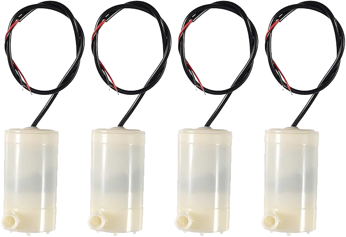
I also experimented with other water pumps. However, they proved to be either too noisy or too weak to effectively push the robots.
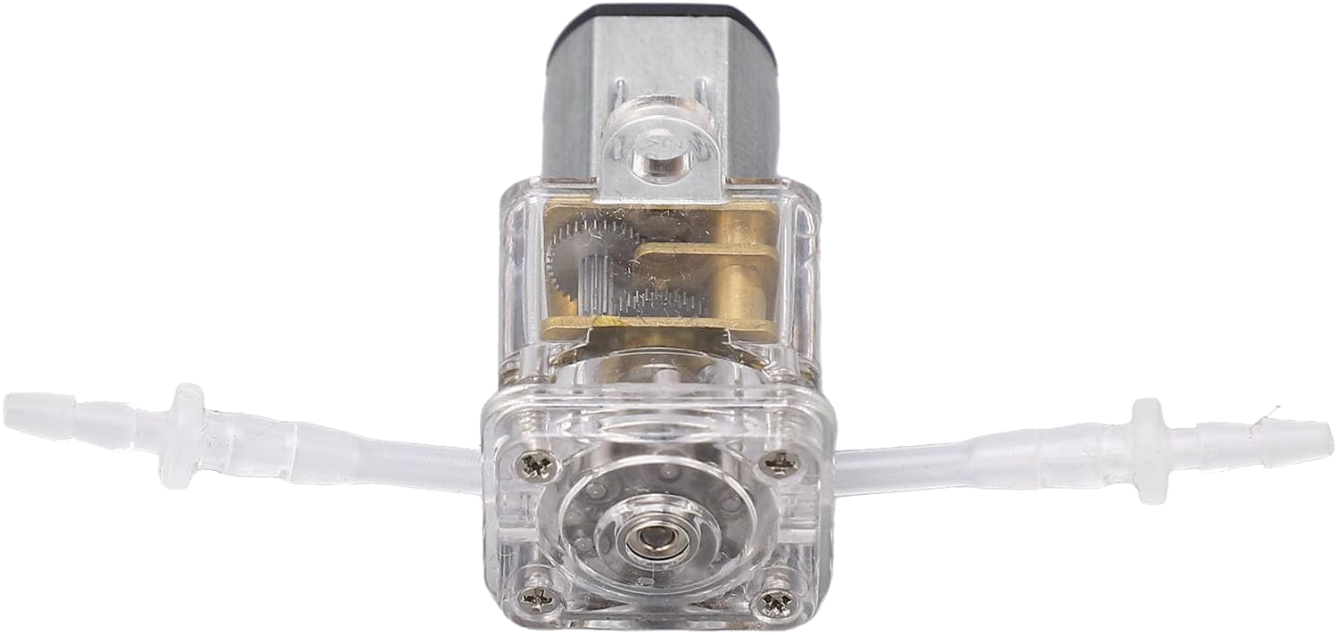
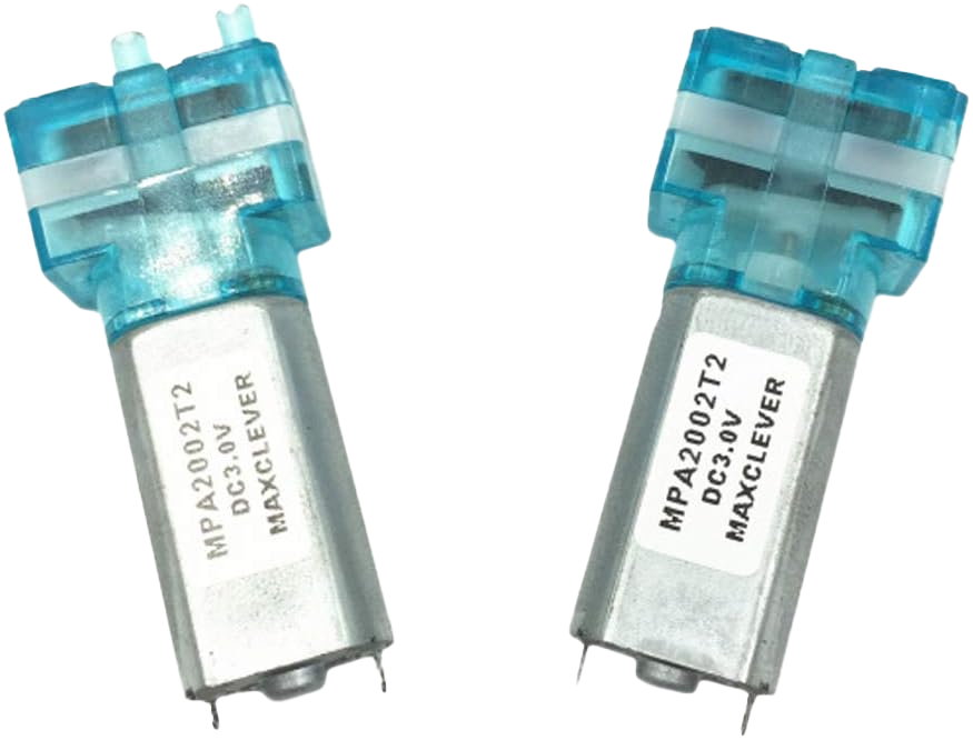
After extensive experimentation with wheel-based locomotion in water, I made a significant discovery that completely changed my approach: I found a mini water pump with unexpectedly powerful thrust capabilities. This led me to abandon the wheel concept entirely and embrace a fundamentally different propulsion method.
The Core Concept: Rather than relying on mechanical wheels to navigate through water, I decided to fully leverage the unique properties of water itself. By utilizing Newton's Third Law of Motion (action and reaction), the water pump can expel water with sufficient force to propel the robot forward. This approach is more elegant, more adaptive to aquatic environments, and opens up new possibilities for robot design and movement.
How It Works: The water pump creates a directional water jet with remarkable thrust. This creates an equal and opposite reaction force that propels the robot body forward through the water. This principle is similar to how aquatic animals move through water, making it a more biomimetic approach to underwater locomotion. The beauty of this method is that it doesn't require complex mechanical systems—just a powerful pump and fluid dynamics.
You can find more details about this water pump model here. This discovery marked a turning point in my project, shifting from mechanical complexity to fluid dynamics elegance.
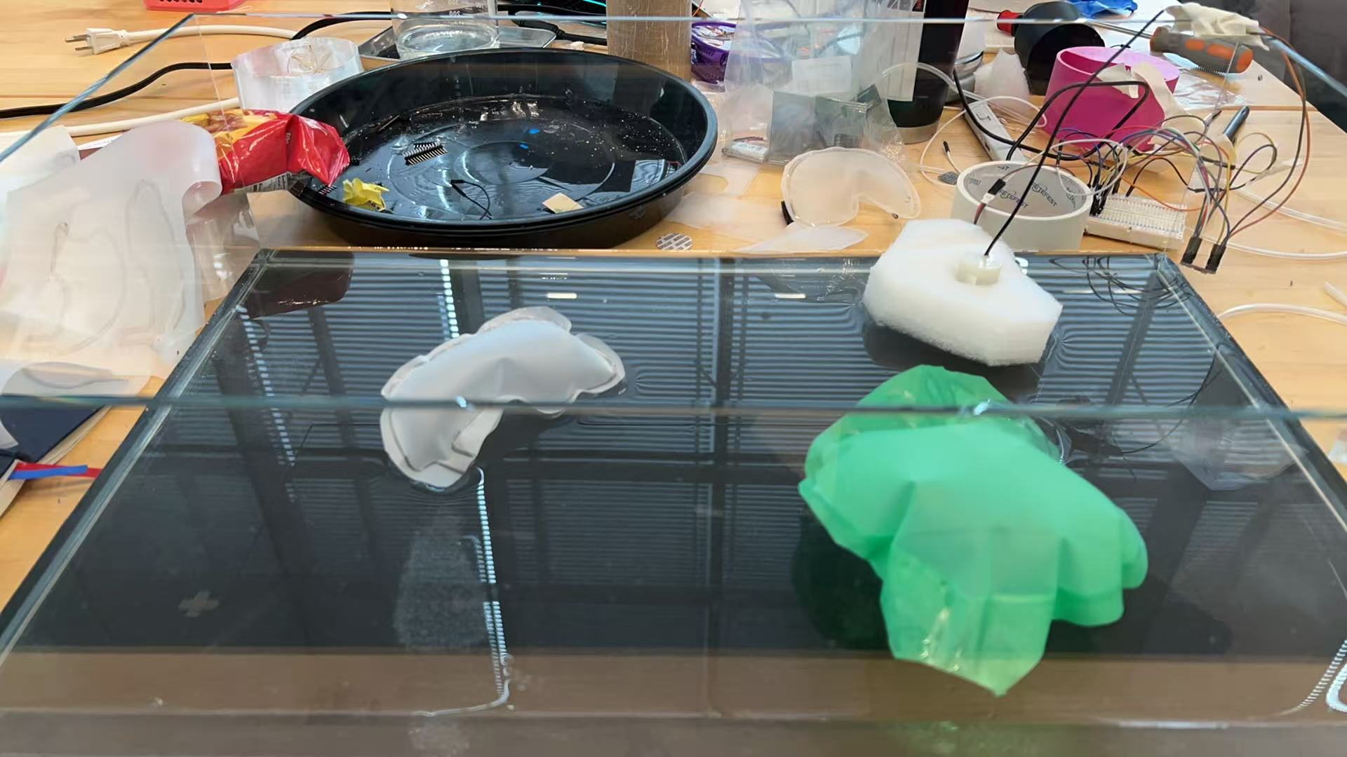
First Test: 3D Printed Shell
My first test involved using the water pump to drive my original 3D-printed shell. I quickly realized that the shell was far too heavy for this propulsion method. Instead of floating or gliding, it sank straight to the bottom. This created a significant amount of friction against the tank floor. The pump simply couldn't generate enough force to overcome this resistance, so the robot remained stuck and couldn't move forward.
Second Test: Sponge Prototype Experiment
Following the challenges with the heavy shell, I decided to simplify the design for the next test. I inserted the water pump directly into a piece of sponge. This lightweight setup floated effortlessly on the water's surface with almost no resistance. As a result, the pump was able to propel the sponge across the water with surprising ease, allowing it to move freely. This successful test confirmed that minimizing weight and friction is the key to achieving effective movement with this propulsion method.
Other Material Explorations
Before discovering the foaming material, I experimented with various other materials to achieve buoyancy, such as airbags and silicone. However, these attempts were less than ideal. They were difficult to customize into specific shapes, and it was challenging to securely integrate the water pump into them.
I also attempted to use PCTG material. Although it offers a nice semi-transparent look, its density is still higher than water. Even a slight addition of weight causes it to sink. This made me realize that relying solely on a boat-like hollow structure is unrealistic if I want to keep the parent robot compact. To achieve the desired size and buoyancy, I must prioritize lightweight materials.
Material Discovery: Foaming 3D Print
While I was considering what material could replace the sponge, my friend Yuxiang gave me a great suggestion. He mentioned a foaming 3D printing filament that he had on hand. This material is designed to be extremely lightweight, which means that even solid printed parts can easily float on the water surface.
With the guidance from the video and Gemini, I was able to achieve the ideal printing results. The material successfully foamed during the printing process to create a structure with a density lower than water. As expected, the final printed parts are lightweight and float perfectly on the water surface.
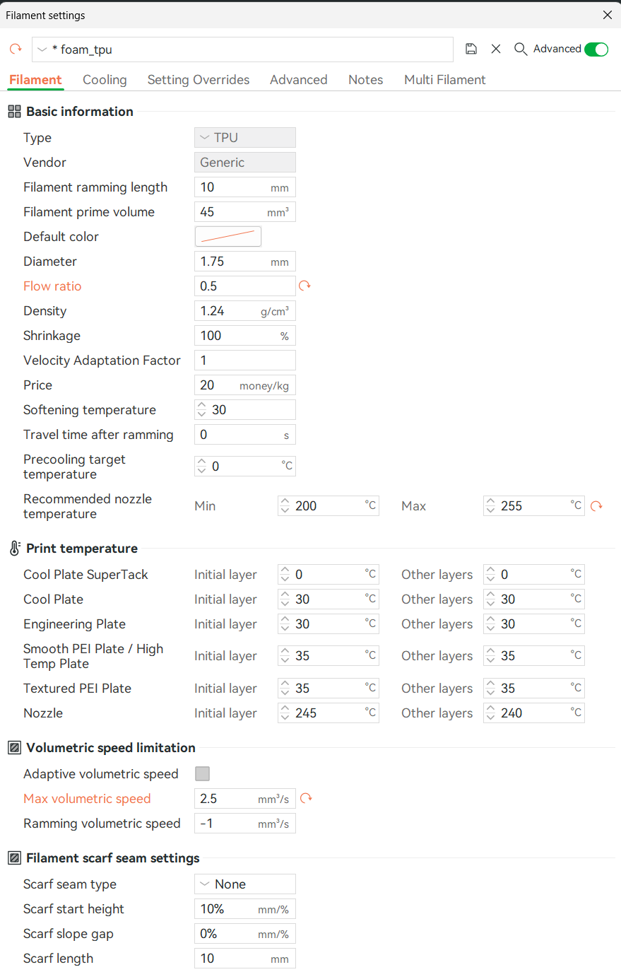
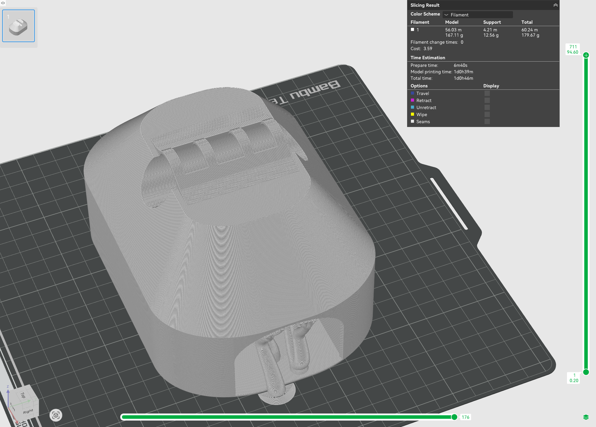
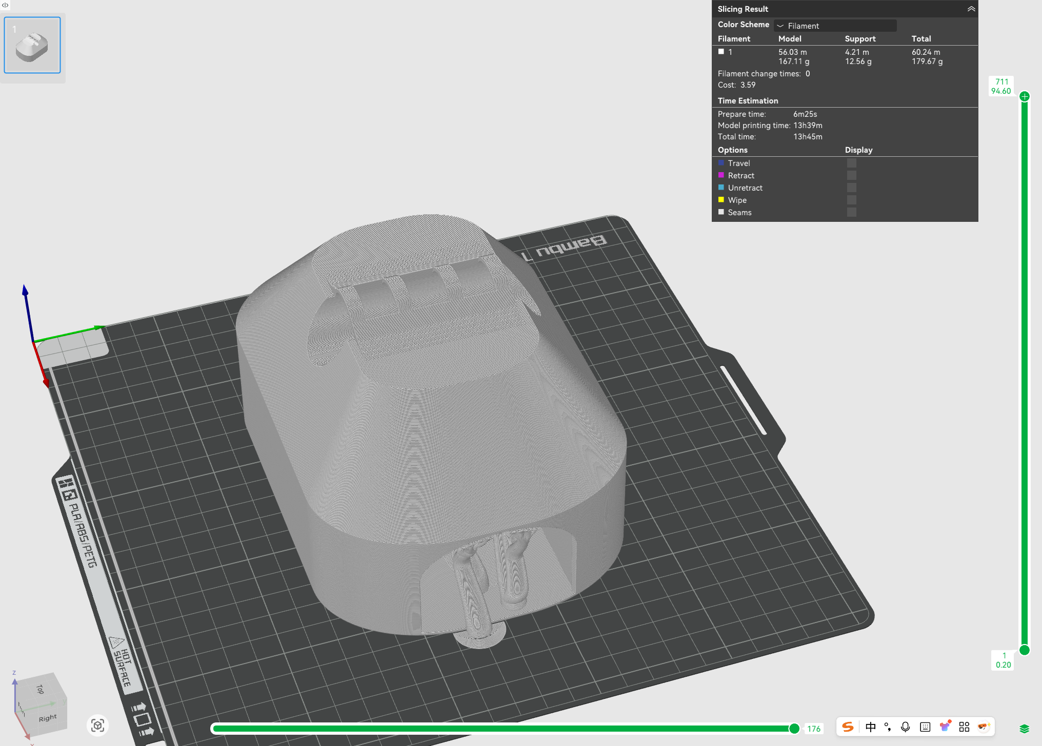
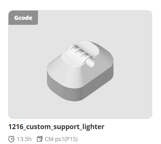
However, I encountered a significant issue: the printing time was excessively long. As shown in the slicer software, it would take at least a day to complete. This made me realize that I needed to explore different print settings to speed up the process.
Optimizing Print Settings
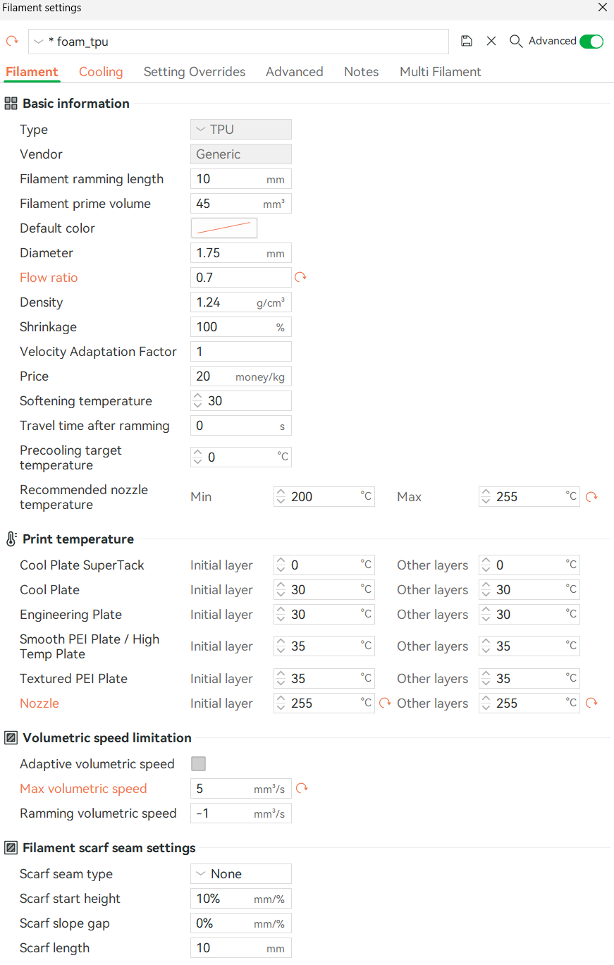
To address the printing time issue, I decided to increase the Max volumetric speed from 2.5 to 5. This adjustment effectively doubled the printing speed, successfully reducing the estimated print time from over a day to around 13 hours.
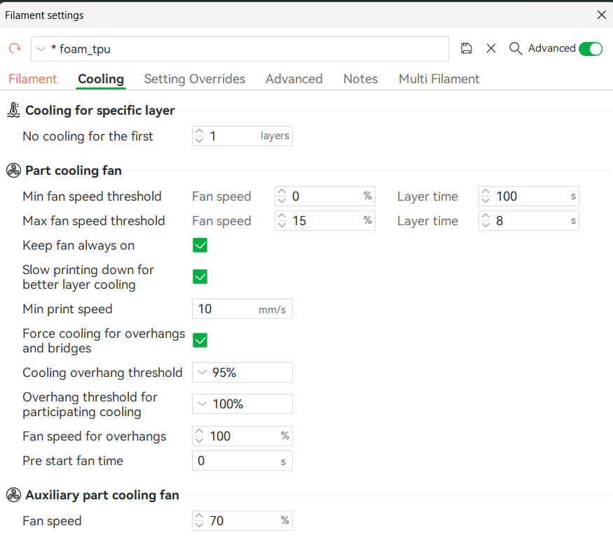
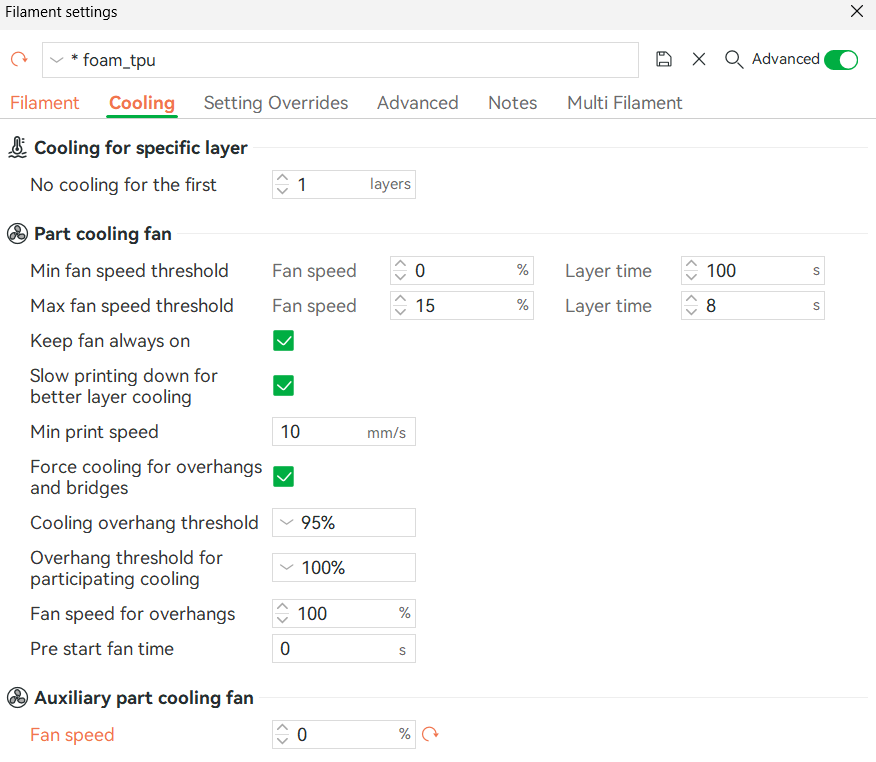
However, printing faster meant I had to adjust other settings to ensure the material would still foam properly. I increased the Nozzle Temperature significantly: the initial layer was raised from 245°C to 255°C, and other layers from 240°C to 255°C. To maintain this high temperature at the nozzle, I turned off the auxiliary part cooling fan.
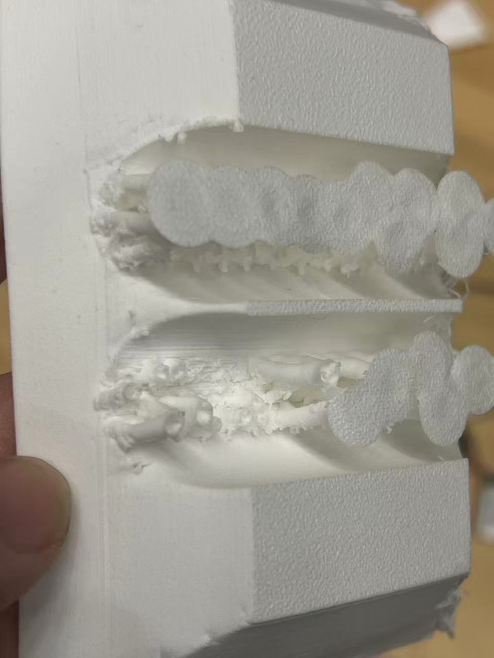
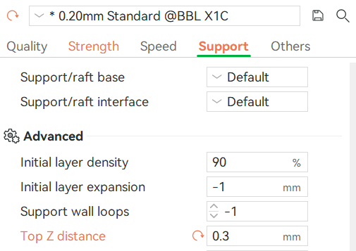
One critical detail to note is the Top Z distance for supports. It is essential to adjust this setting carefully. If the distance is too small, the supports will fuse too tightly with the printed part. I learned this the hard way when I found it nearly impossible to remove the support structures from one of my prints.
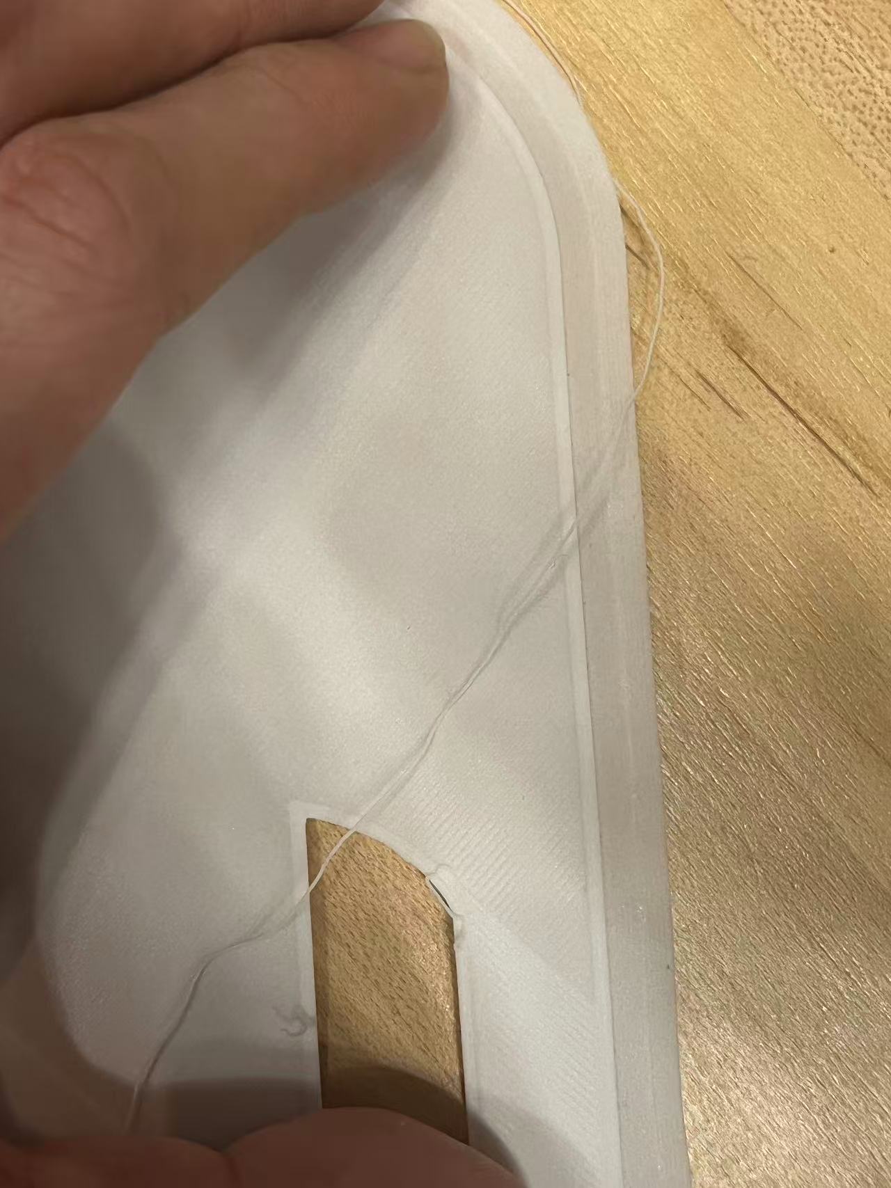
Another crucial observation is that this foaming material, much like TPU, requires minimal to no brim for bed adhesion. In my initial attempts, I set the Brim Type to 'Outer brim only' with a 10mm width. Unfortunately, this resulted in the brim fusing excessively to the part, making it extremely difficult to remove. For future prints, I recommend disabling the brim or using a much smaller width.
Another lesson learned involves the number of Wall Loops and the density of supports. Here is another failed example: because this foaming material is soft like TPU, it requires sufficient structural support during printing. In an attempt to speed up the print, I intentionally reduced the amount of support, but the result proved how critical adequate support is, especially for such flexible materials.
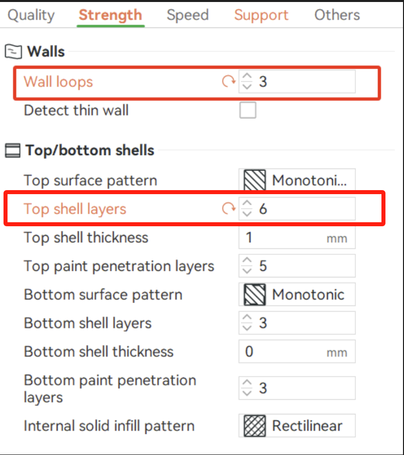
Besides structural integrity, waterproofing was a major concern. To ensure the object is watertight, I made specific adjustments unrelated to the general structure: I increased the Wall Loops to 3 (from the default 2) and the Top Shell Layers to 6 (from the default 5). These extra layers provide a more robust barrier against water ingress.
Finally, to prevent the Bambu P1S printer itself from overheating due to these high-temperature settings, I printed with the side panel open to allow for better heat dissipation.
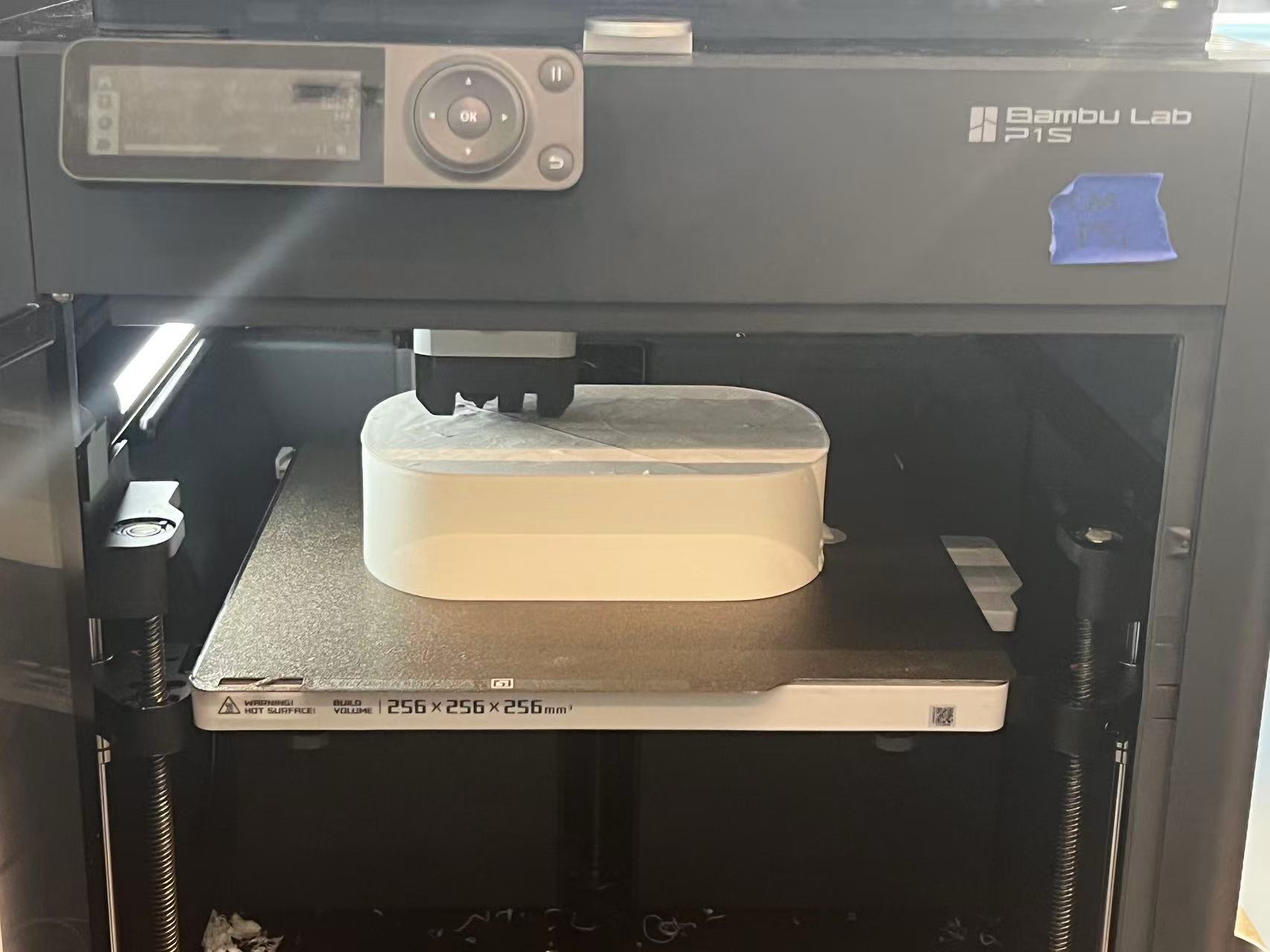
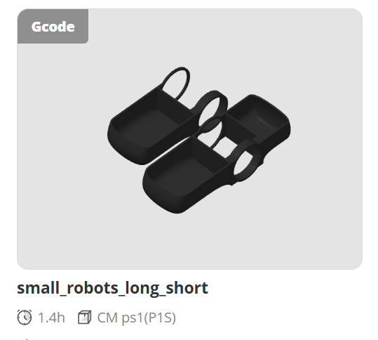
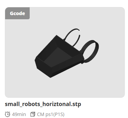
Baby Robot 3D Print
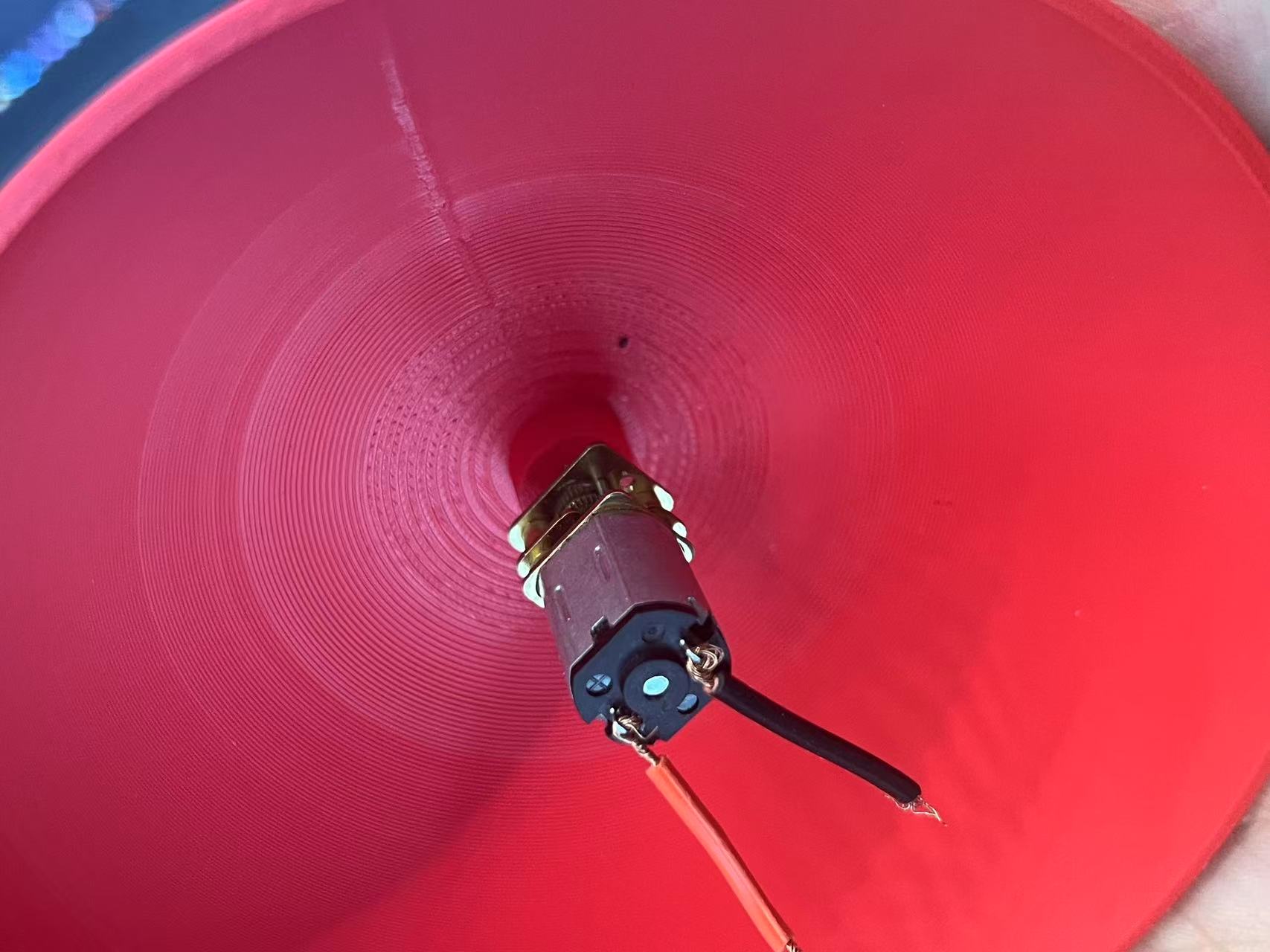
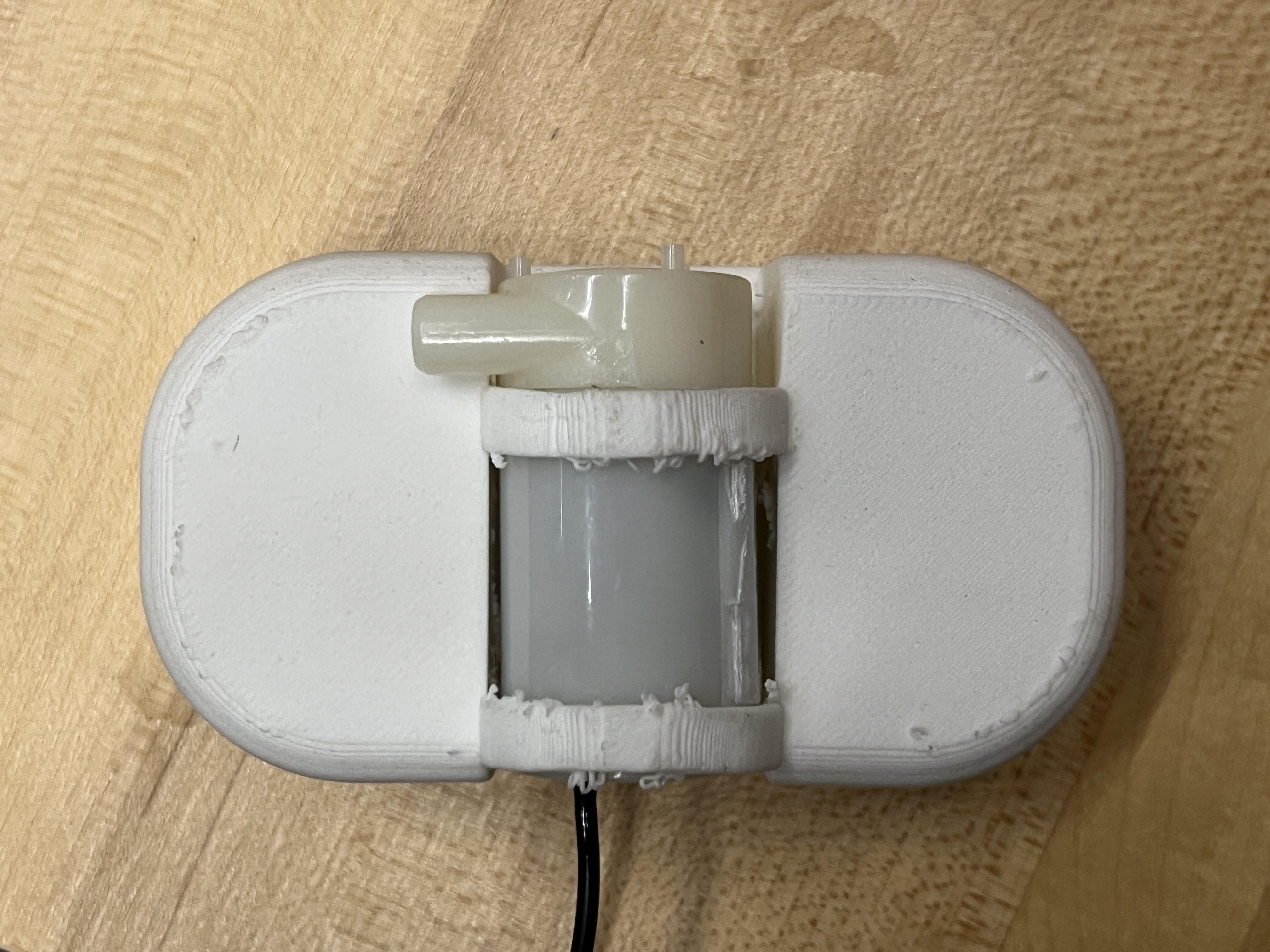
I explored the impact of the water pump's position on the robot's floating stability. I experimented with placing it on the side versus the center. The results showed that the center position is the most stable and prevents the robot from tipping over on the water surface.
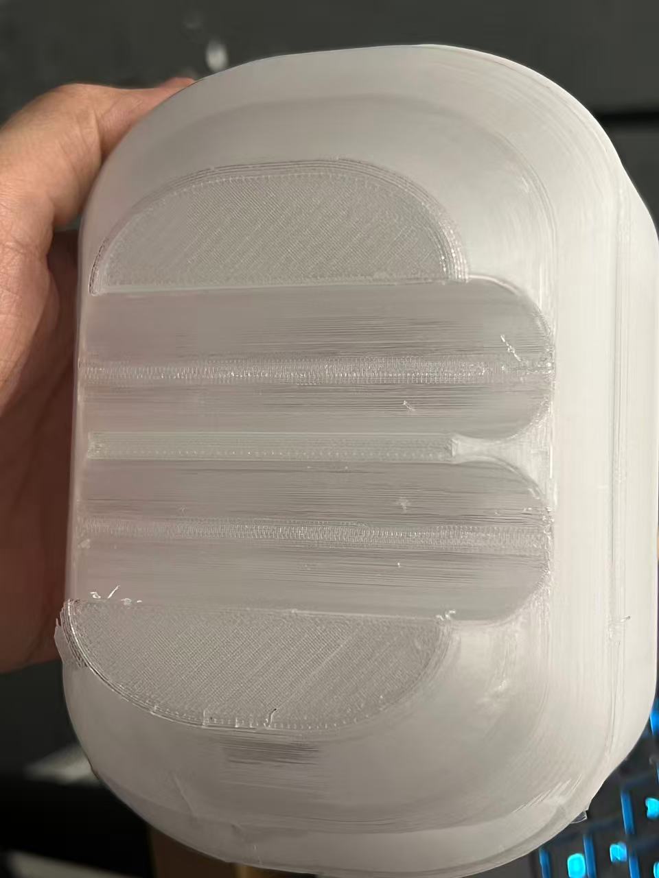
I also tested what kind of ring structure would best secure the water pump. I ultimately chose a closed ring design. Since the foaming material is relatively soft and has some shrinkage properties, a simple stiff closed ring holds the pump securely without needing an opening for flexibility, which would likely be required if printing with a rigid material like PLA.
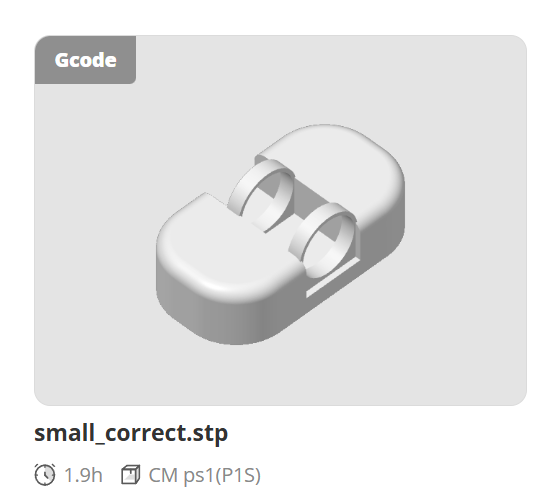
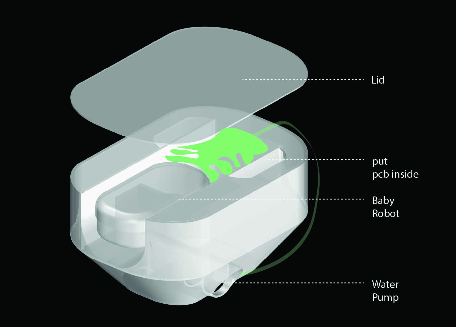
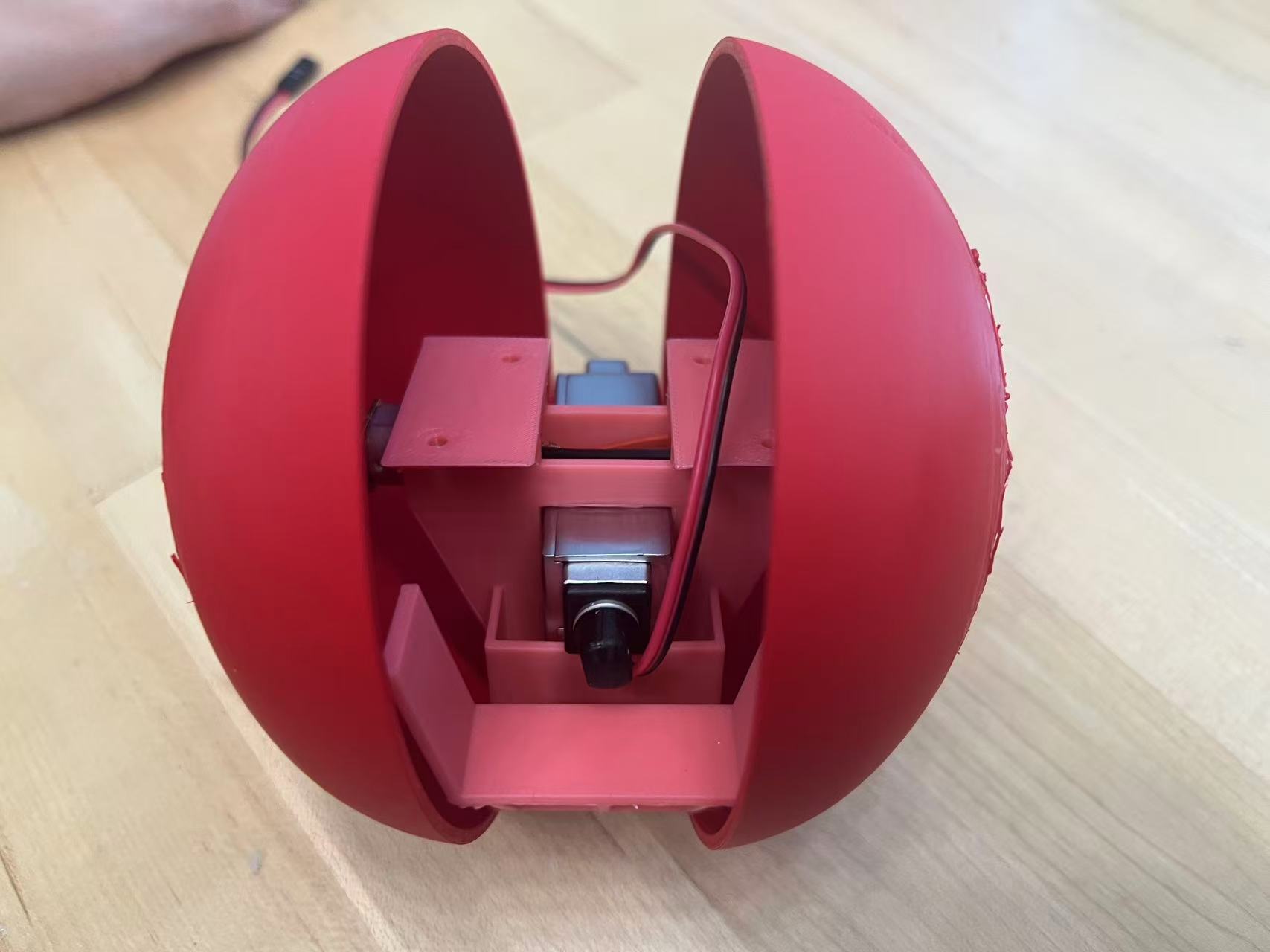
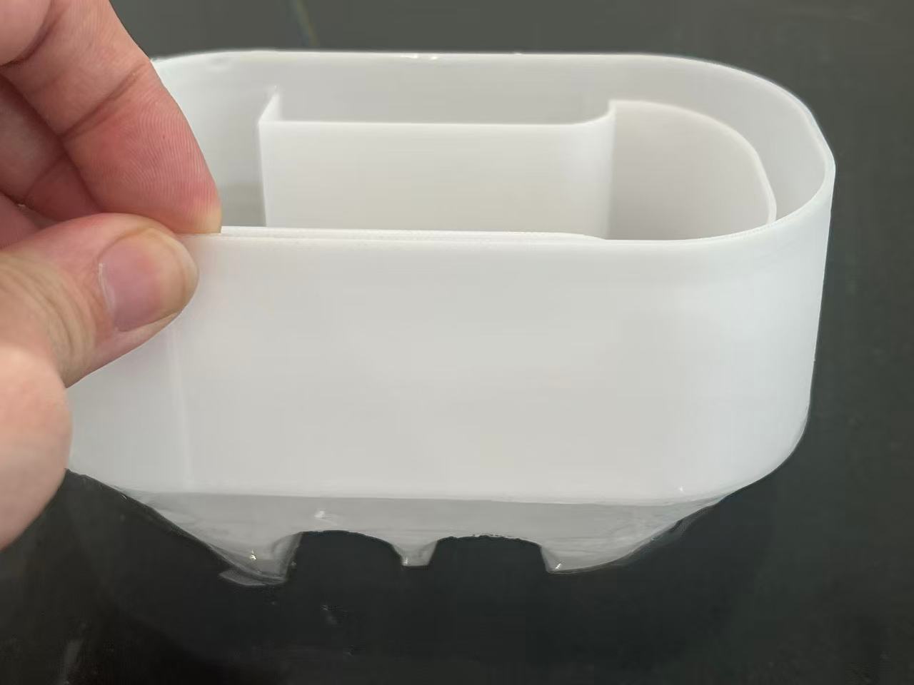
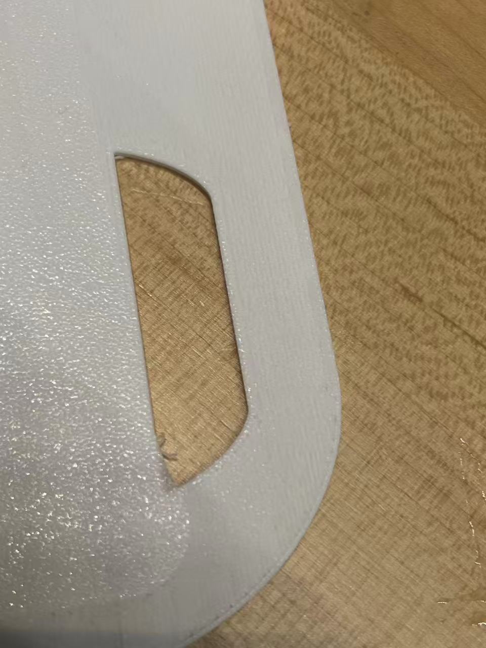
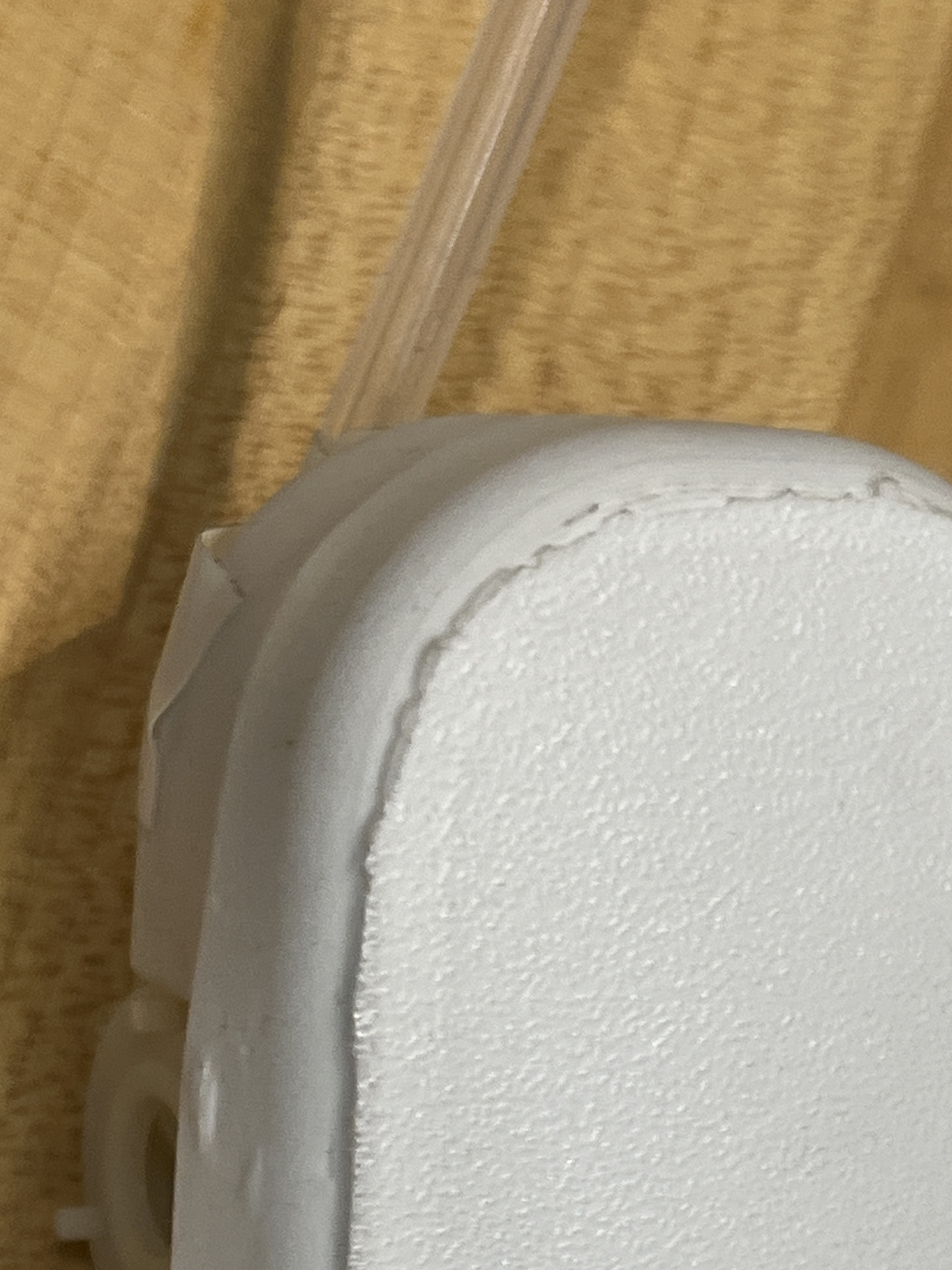
Regarding the dimensions, the baby robot has strict size constraints as it must fit comfortably inside the parent robot's body. The design features a central cutout specifically sized for the water pump. Two side recesses are carved out to tightly house the Xiao ESP32 (functioning as the controller/switch) and the battery. Despite these functional requirements, I aimed for a rounded, organic shape to maintain a "cute" and biological aesthetic.
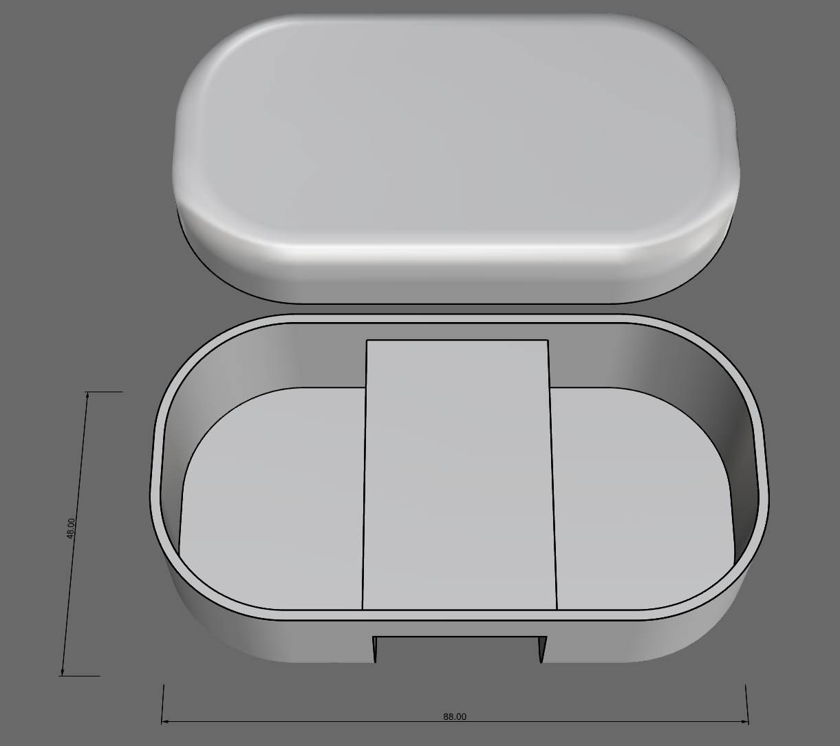
Another crucial design aspect was weight distribution. I split the electronics, placing them on opposite sides of the robot's interior. This balanced the weight, ensuring the robot would float evenly and stably on the water.
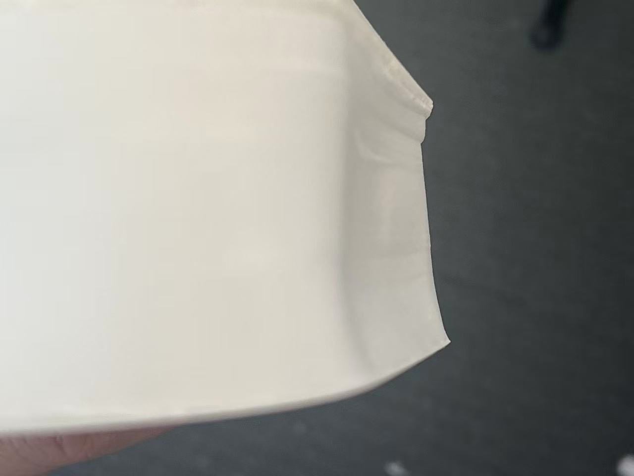
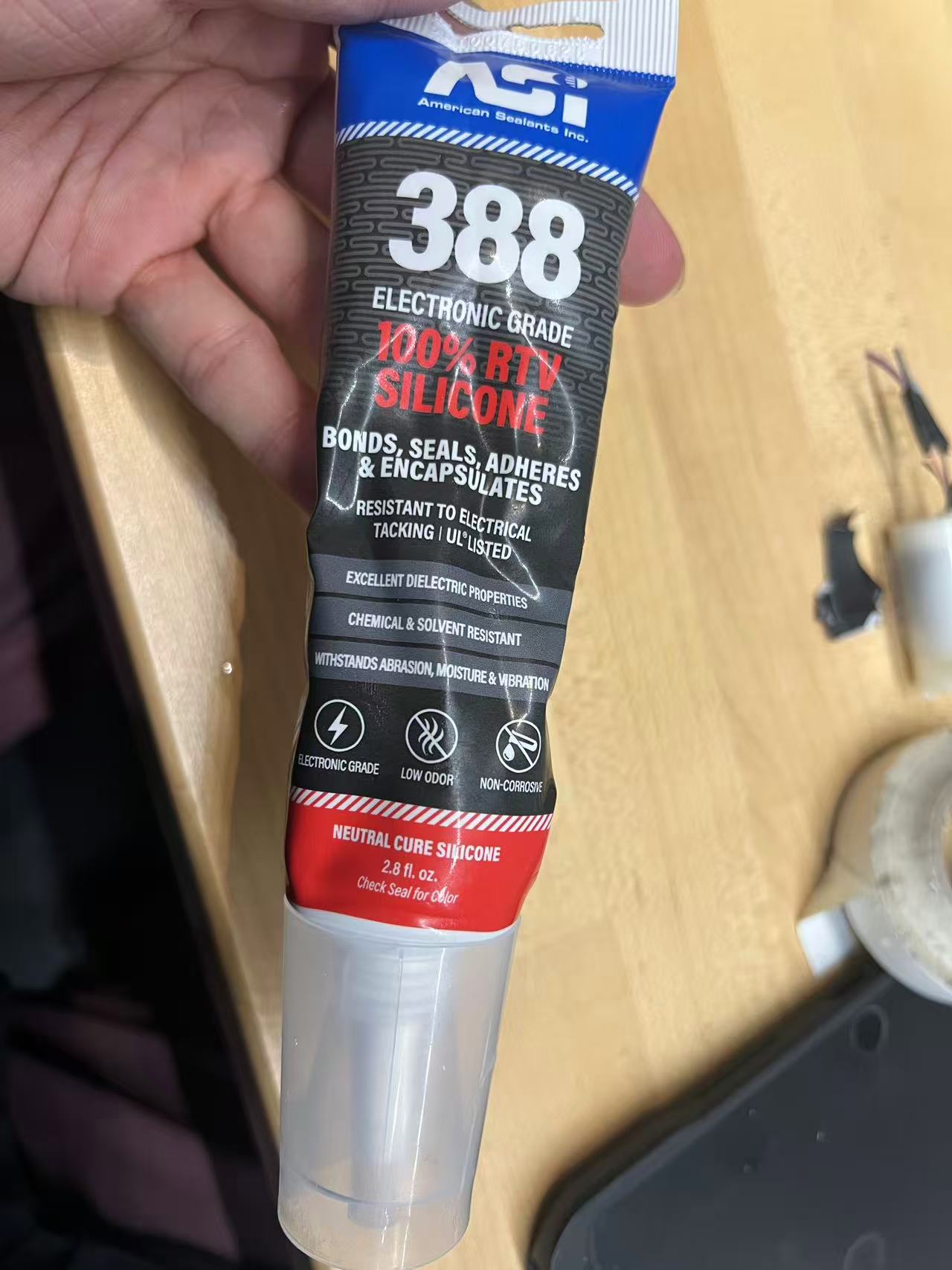
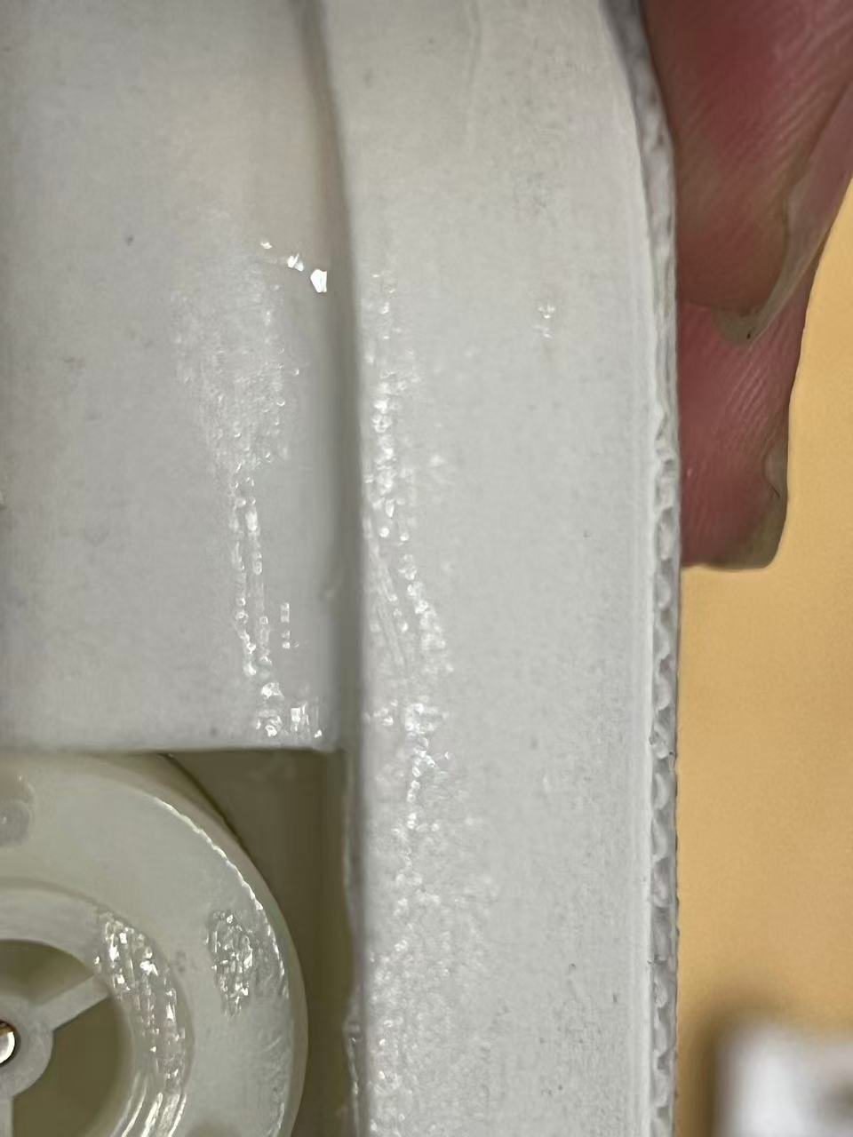
Since the foaming material is porous and the lid is a separate print, leakage prevention was vital. I applied waterproof glue around the lid's seam to seal it completely, ensuring no water could enter the electronics compartment.
I then conducted a full test combining the water pump, the printed case, and the electronics. The robot successfully floated and the motor worked! However, because it only had a single water outlet that wasn't perfectly aligned with the center of mass, it mostly spun in circles instead of moving straight.
The spinning happened because the water jet pushed from one side, but I couldn't move the pump because the robot's weight needs to stay balanced. My solution was to use a tube to guide the water flow. I taped a tube to the bottom to redirect the jet, which helped stop the spinning. It's a bit messy for now, but I plan to design and 3D print a proper part to hold the tube in place permanently.
Here is the test video after adding the tube. It works much better! The path isn't perfectly straight yet, but it's a huge improvement over just spinning in circles.
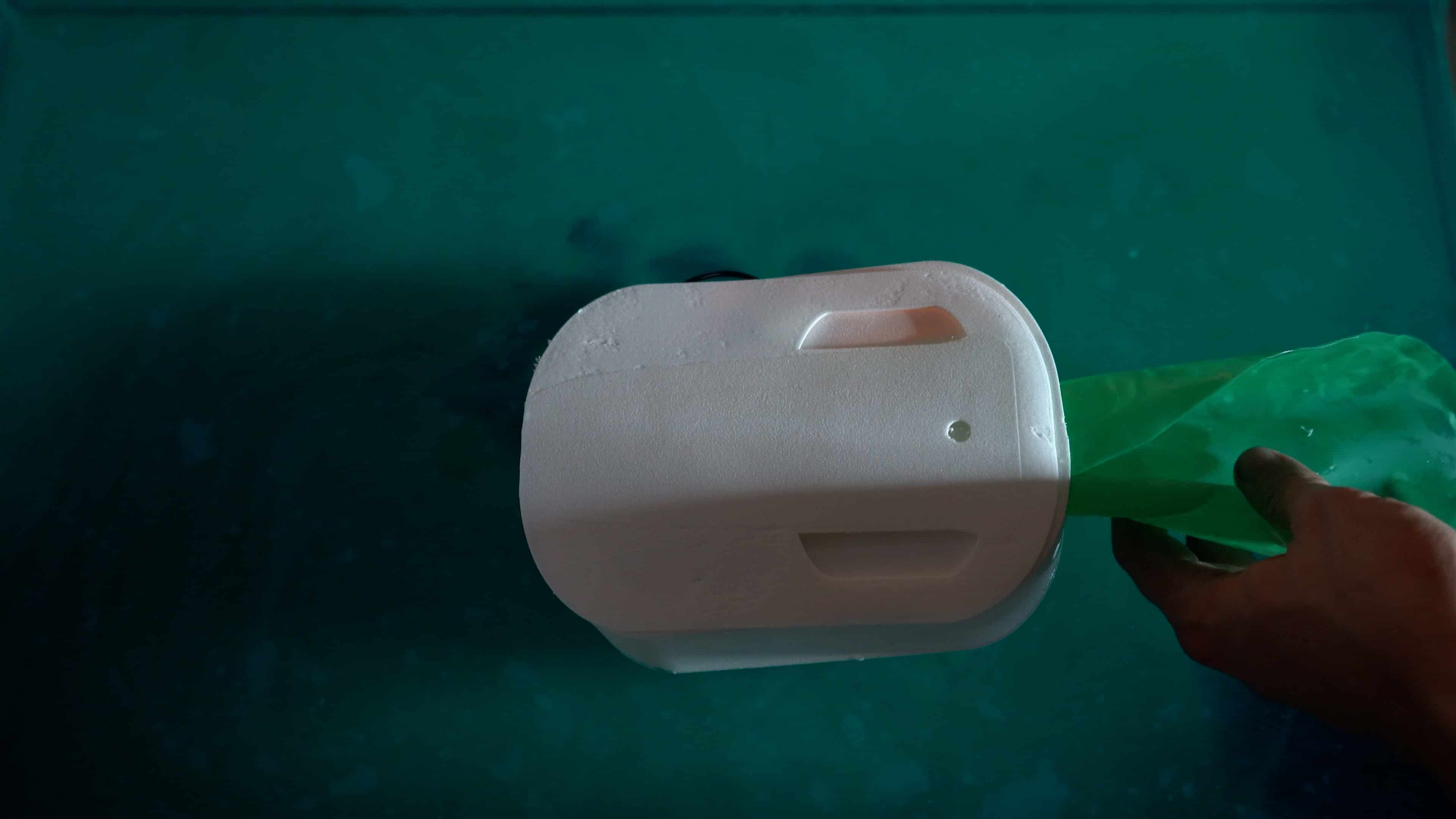
Final Assembly
For the final demonstration, I moved the entire setup to a glass fish tank to clearly visualize the process. The assembly involved carefully placing the electronics and the custom PCB into the parent robot's shell, followed by inserting the inflatable airbag mechanism. Once everything was sealed and submerged, I used the smartphone interface to wirelessly control the water pump, initiating the inflation and the birth sequence.
Fish Tank Link: Amazon