After Neil's lecture, the week began with an electronics recitation with Anthony followed by an electronics workshop with Quentin. After a soldering introduction, Quentin presented us with his QPAD boards that were imbued with touch sensing capabilities, much like a video game controller. Here is the QPAD board documentation (kindly written up by Quentin for our reference complete with schematics and sample code). From here I set up my station and got to soldering. It took a few tries to get the solder to melt properly, but other than that it went pretty smoothly. Some memorable tips from Quentin were to tin the pads before adding the components, to lock down components by soldering opposite corners first, and to address any shorts either using a copper braid or a solder sucker. The soft-tipped ones work best.
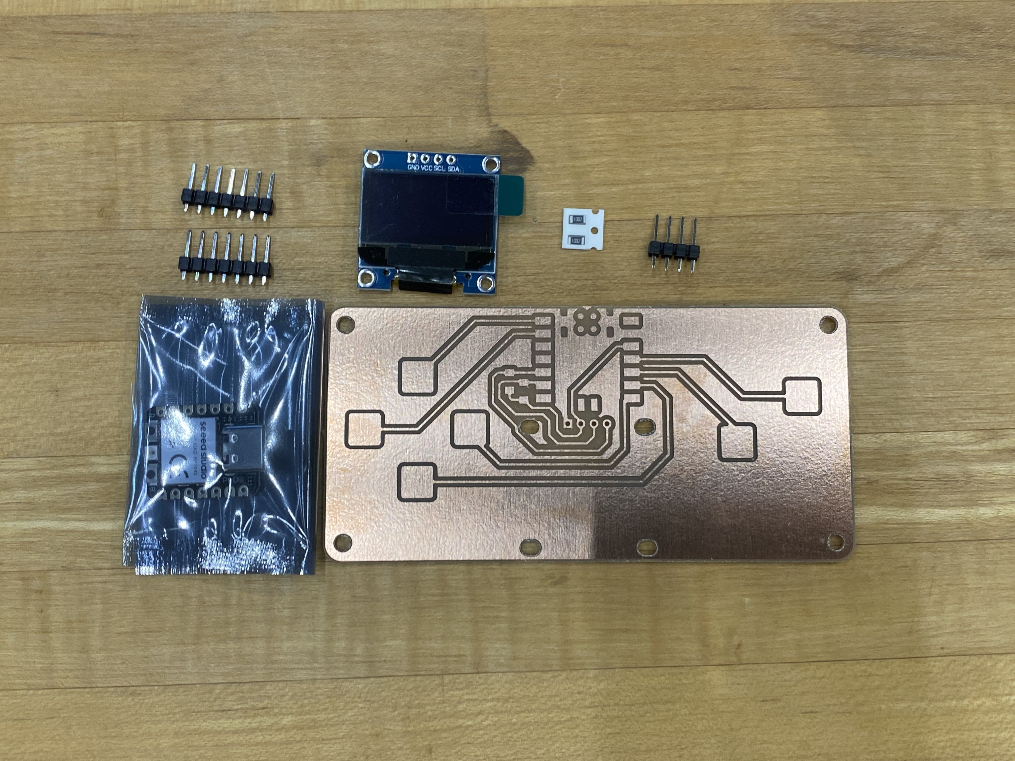
I started with these components: a Seeed Xiao RP2040, two 10k Ohm resistors, an OLED, a 1x4 header, and the QPAD-Xiao board itself.
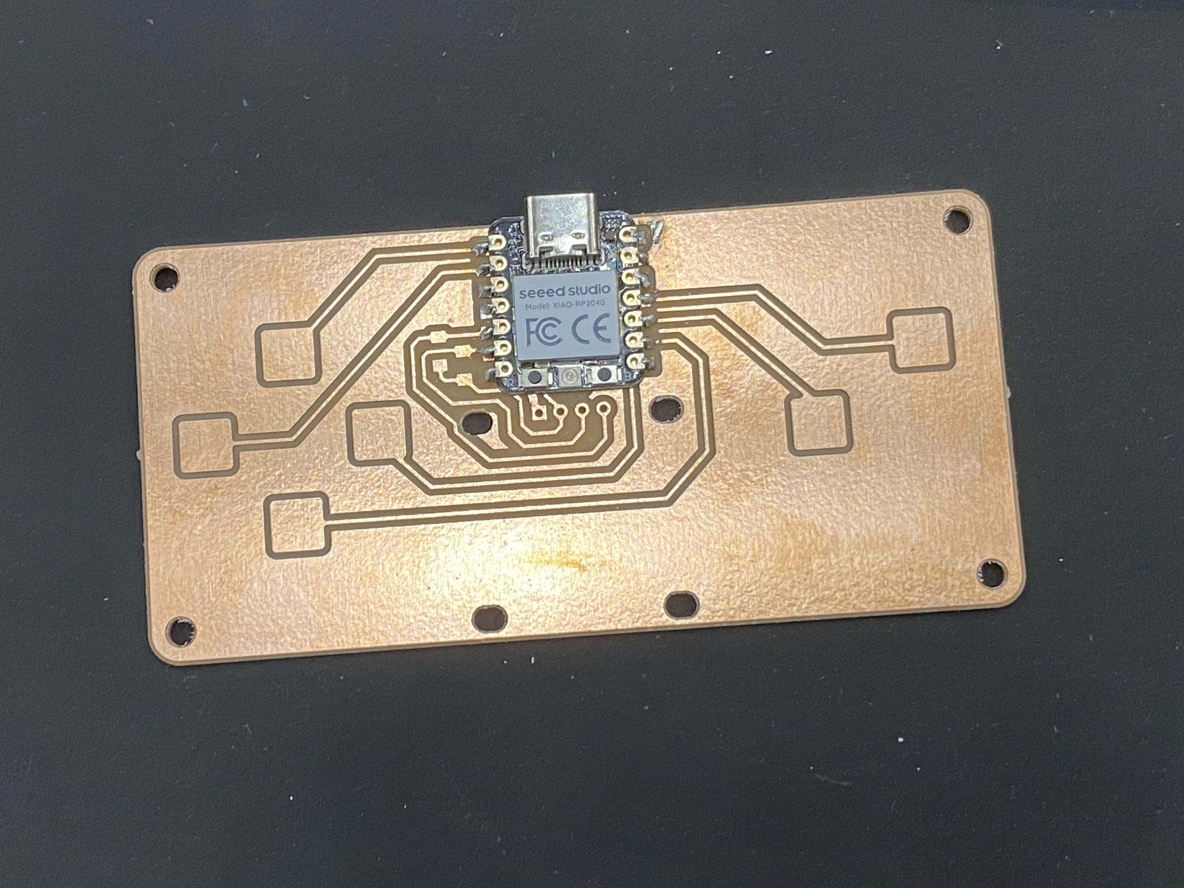
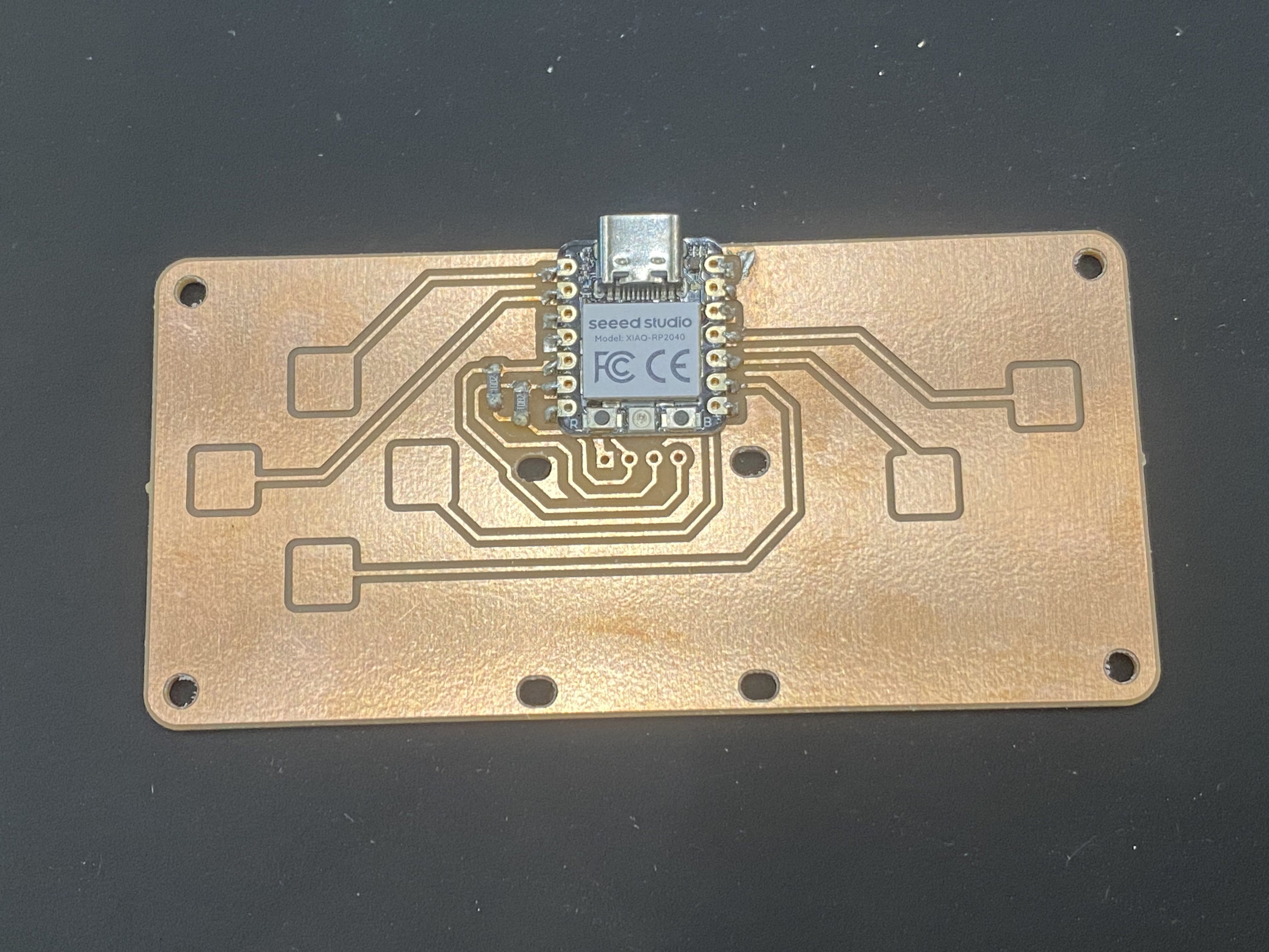
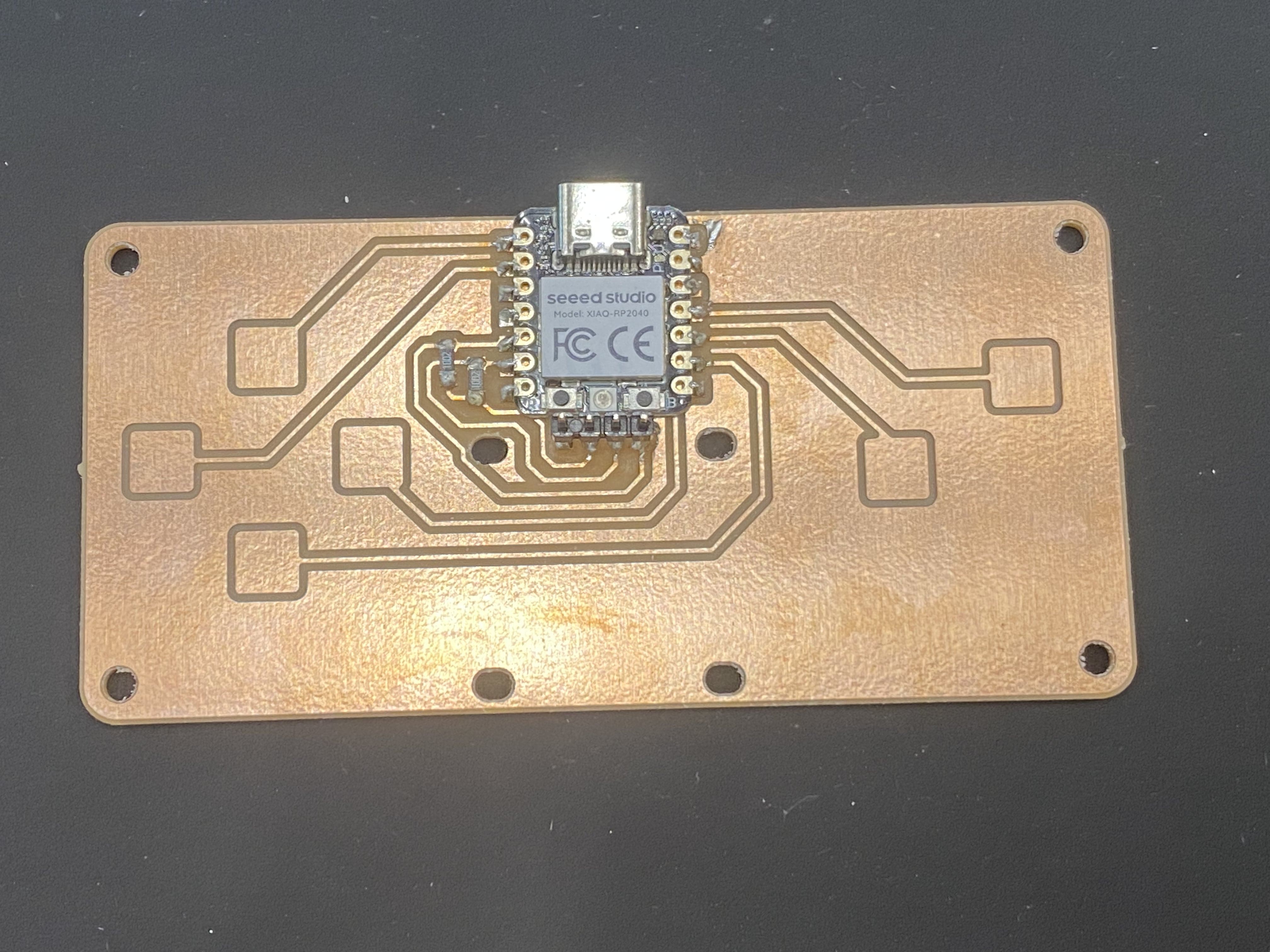
Then I soldered the Xiao, resistors, header, and screen. Along the way, I had to fix some shorts. Using a bit of flux and the soldering iron were sufficient here.
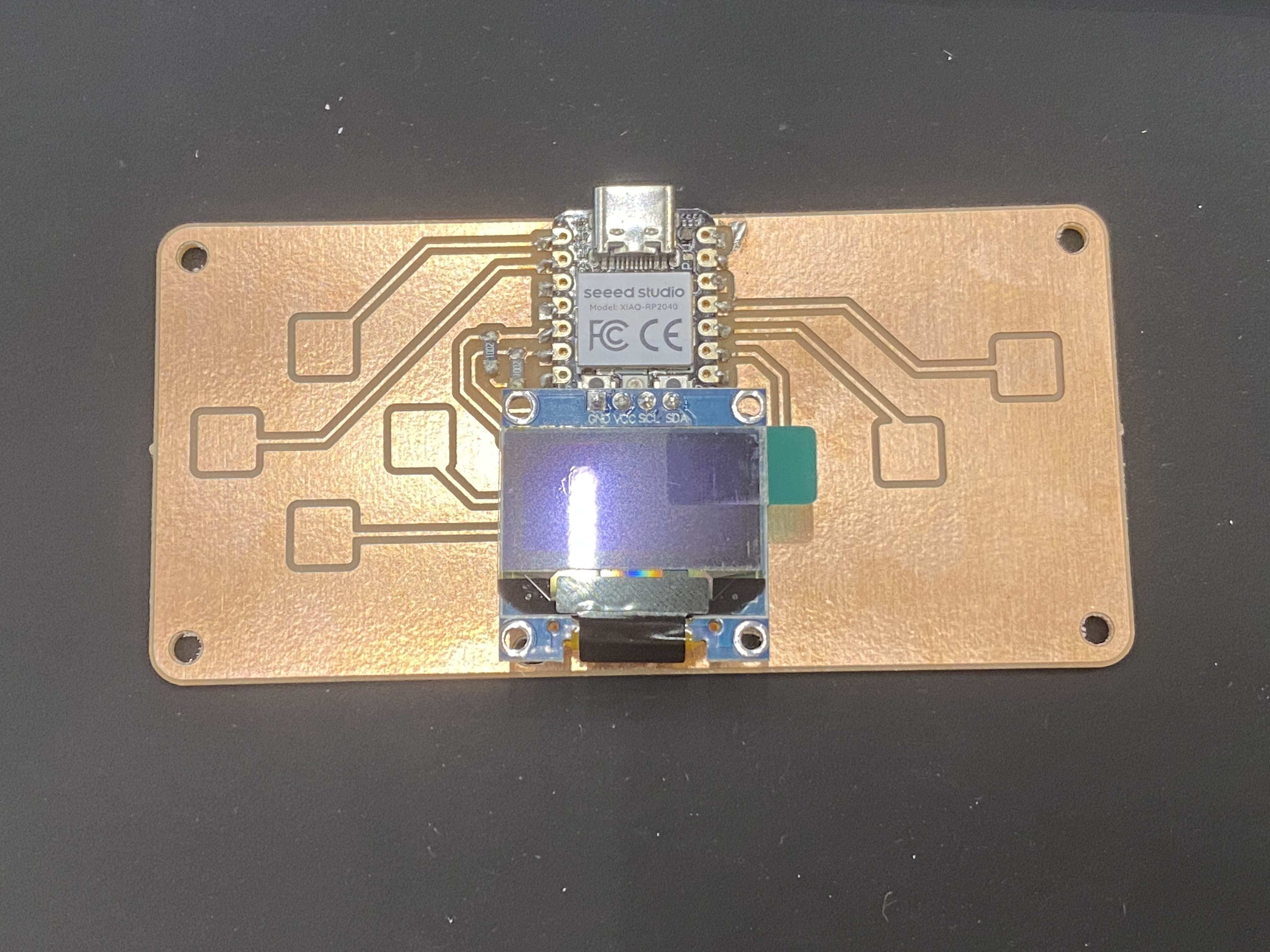
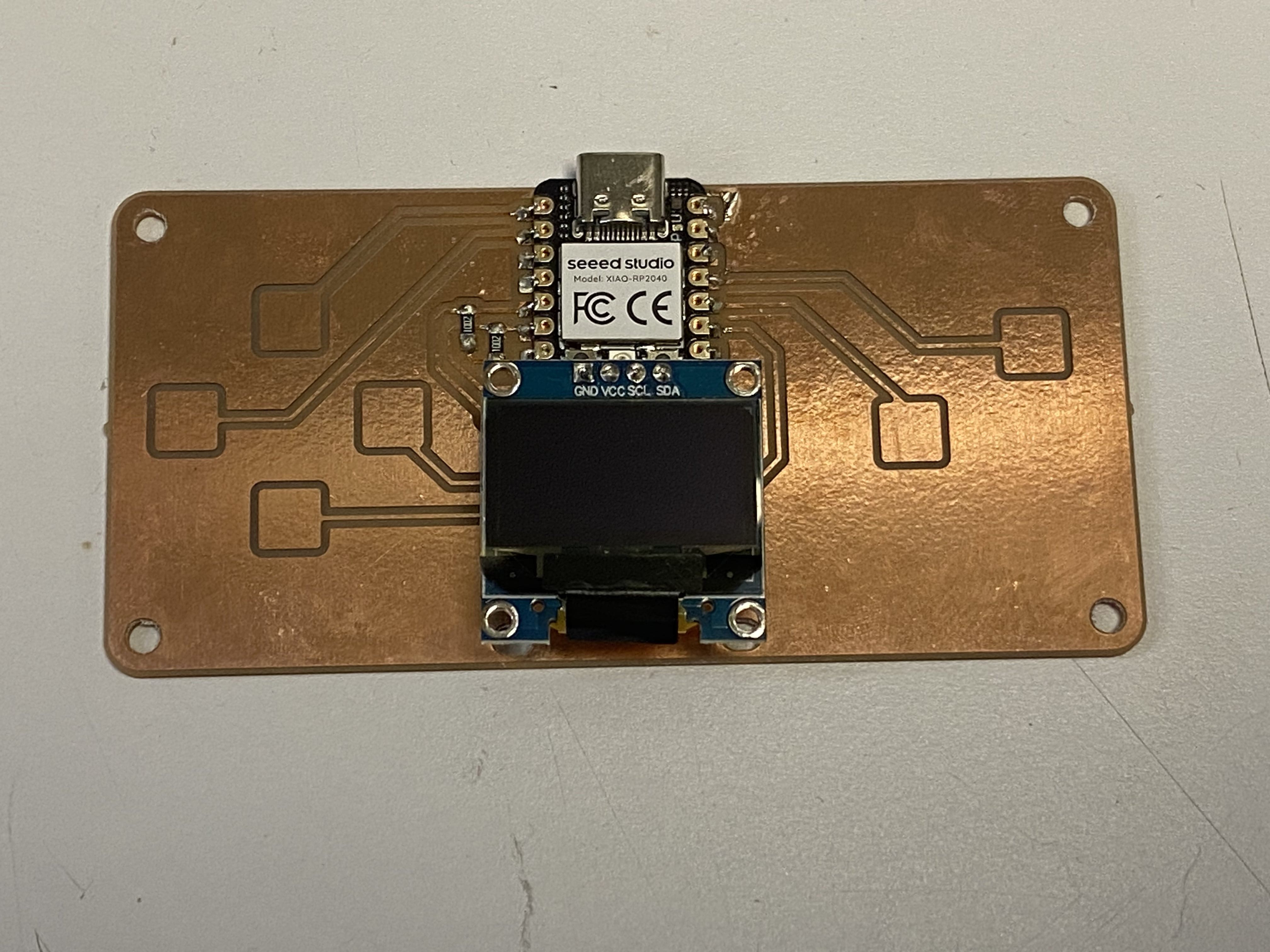
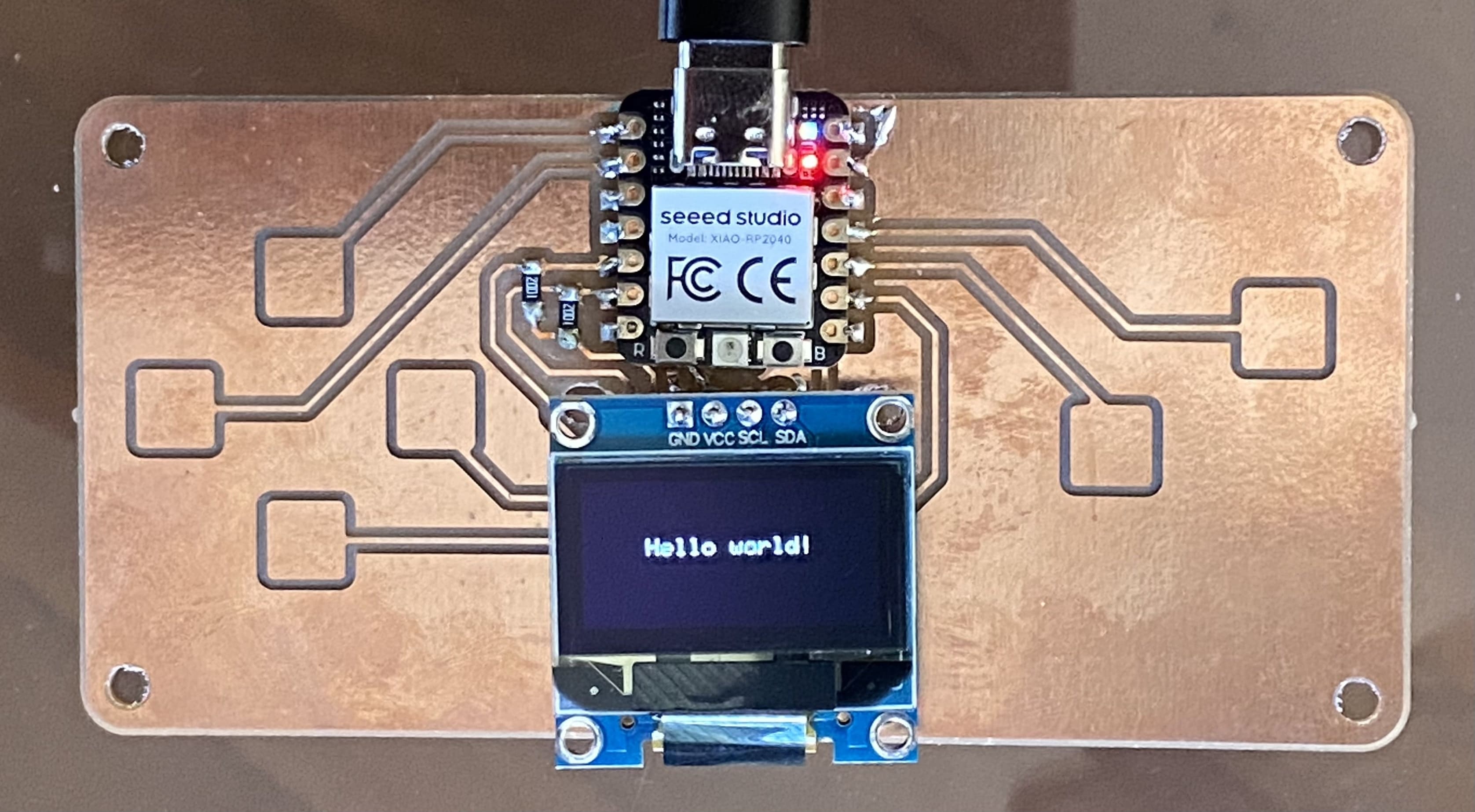
Here is my fully assembled board, with the screen protector removed. I was really happy with how it came out.
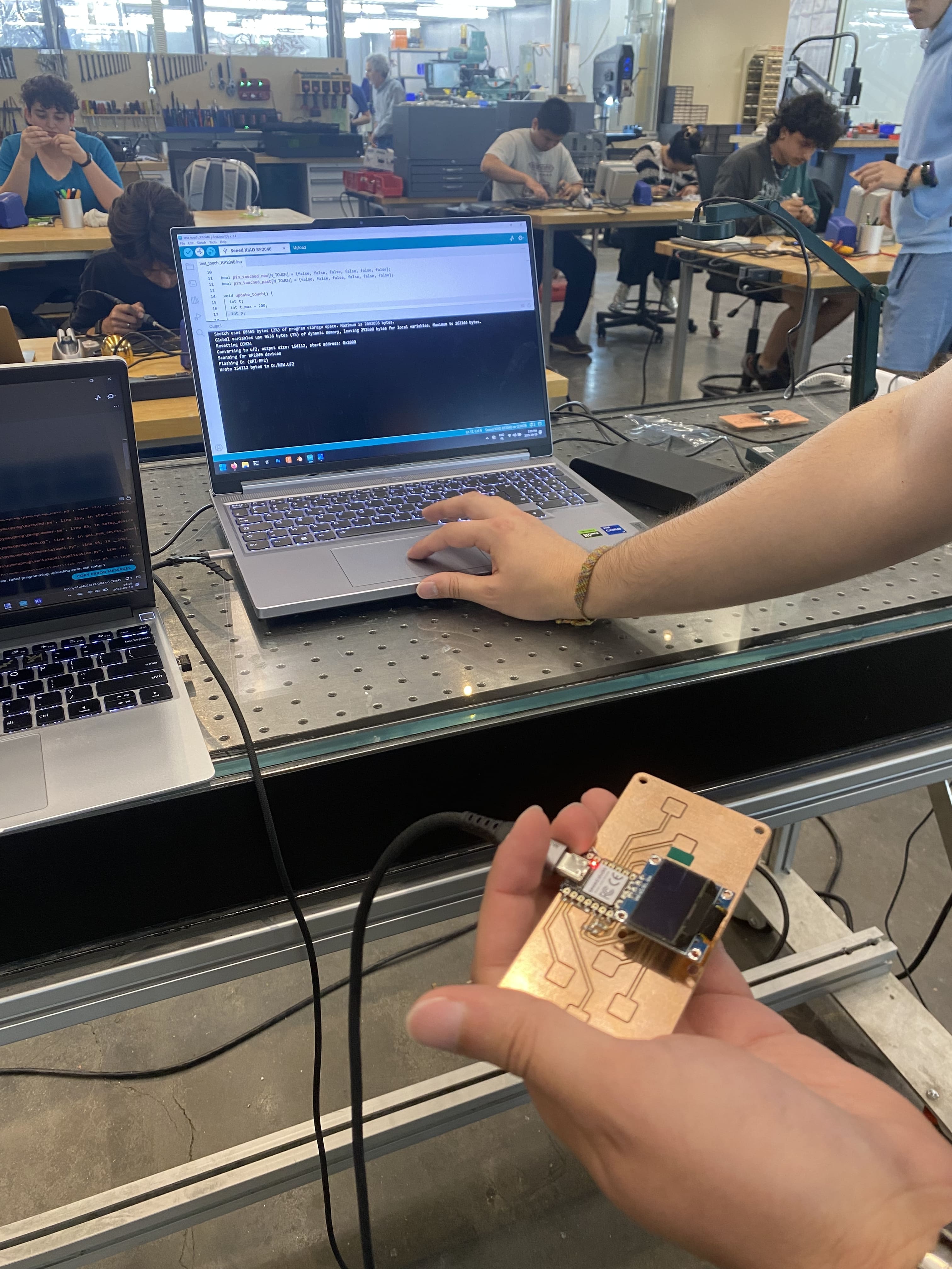
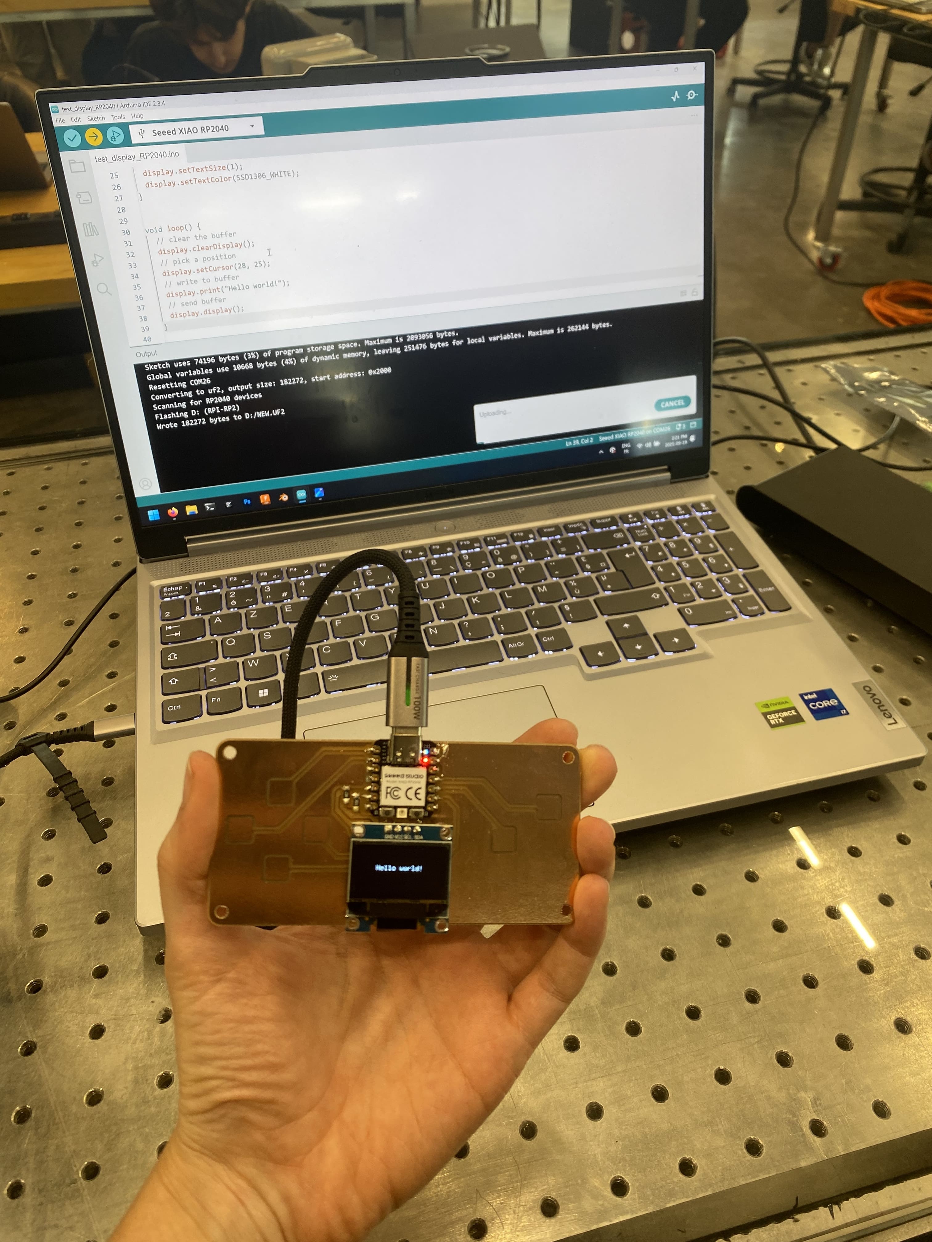
Next, I tested that the board was working with Quentin. First, we plugged the QPAD-Xiao into the computer. It connected successfully and the LED turned on.
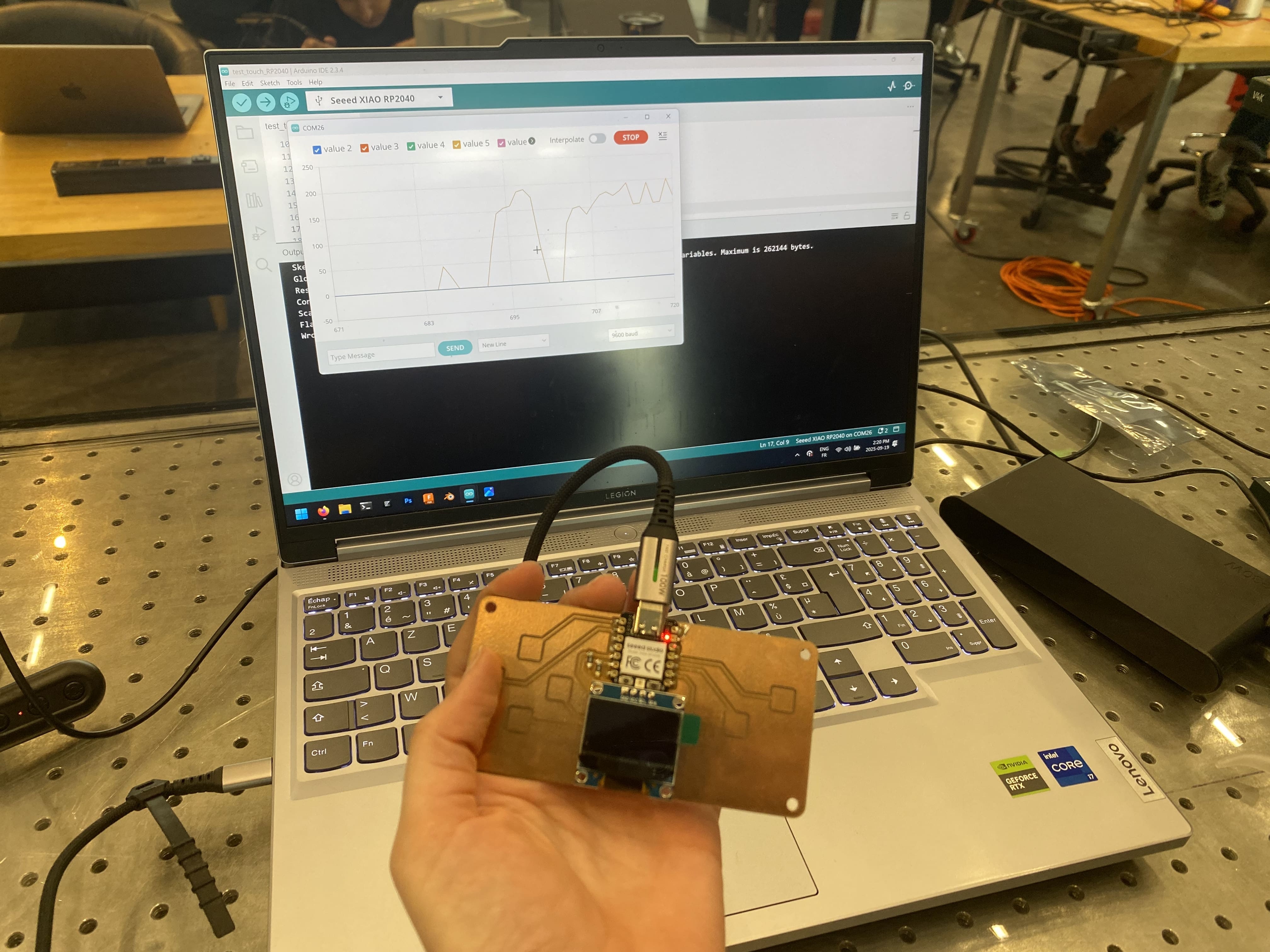
After this, we tested the touchpad and display using Quentin's example code. In both cases everything seemed to be working well.
Next for me is to try using my own code on the QPAD-Xiao. Stay tuned for more!
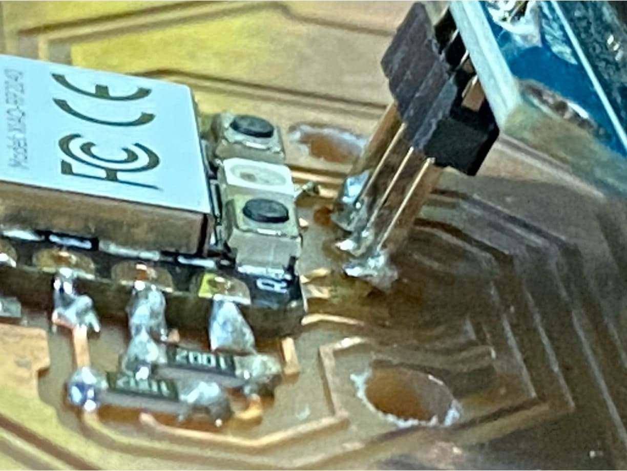
A brief note about the QPAD-Xiao's design. In order to make it more easily solderable, the OLED is attached via a 1x4 header and left floating. Since this header is on only one side of the OLED, this effectively creates a lever arm that makes the header susceptible to breaking. Applying even a small force on the bottom of the OLED is enough to impart a torque that tears up the traces connected to the header. Thus, I ended up with this situation, where all four pins had torn up the copper traces and the OLED was no longer floating.
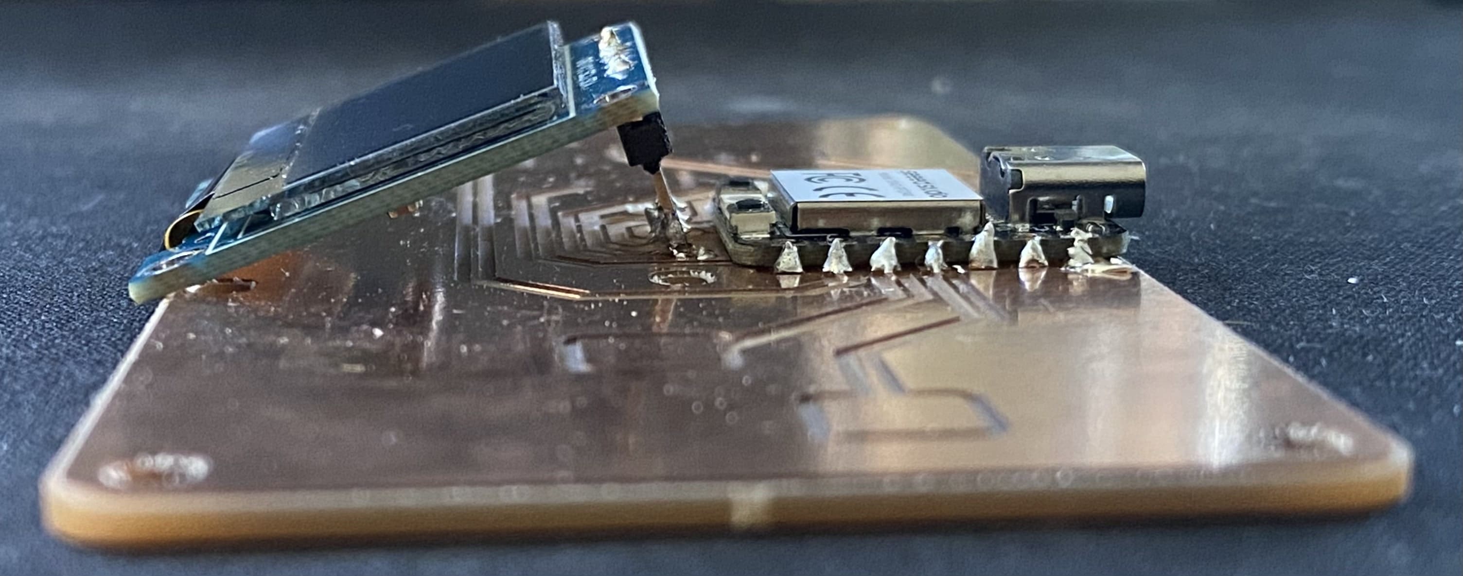
It was not looking good. The traces were completely broken and the OLED was no longer supported in the slightest.
I got some help from a much more experienced solderer than me, Colin, and we brought out the microscope to take a closer look. Putting the board on a makeshift ramp and using the microscope gave us a chance. Soon, traces one and two were back on track!
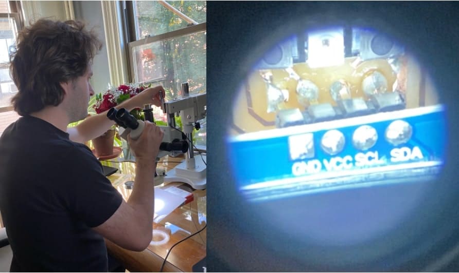
The zomboard has awoken.
Next was the task of understanding and programming the board. I began by looking at the data sheet for the Seeed Xiao RP2040, the microcontroller I soldered onto the QPAD-Xiao Quentin designed and would be using for the remainder of the week. Particularly useful to me was the pinout diagram.
Since I want to make a ruling machine for my final project, I thought it would be fun to use programming the QPAD-Xiao as a chance to create a pixel artboard. That way, I would have code at the ready for drawing simple images with the ruling machine once everything was up and running. Since the QPAD has six touchpad inputs, I thought I could use four as arrow keys to move the selected grouping of pixels and the remaining two as color selectors between black and white (for negative space). With this, I hoped to have a pixel art generator. My plan was to start by modifying Quentin’s touch test program in the Arduino IDE to register separate pads independently. Although I typically don't subscribe to vibecoding, I opted to use ChatGPT to help create a version of the code. The full conversation can be found here. First, I made the "arrow key" pads control the position of a small white block. Aside from the Arduino IDE not registering the device immediately, everything else worked pretty immediately.
It worked exactly as expected. Next I needed to add the ability to color in pixels. Here is the prompt I used with ChatGPT to tweak the output. I ended up changing the "pixel" size on my own to make creating images faster.
"modify this so that the screen is actually made up of a bunch of "pixels" (these smaller squares) for the purpose of making pixel art. Make it so that the arrow keys let you move from selecting the first "pixel" to the second and so on, indicated by slow blinking or similar effect of the highlighted "pixel". The other two touch pads that I mentioned are to be put to good use now. Make one of them assign the "pixel" that the user is on to be white, and make the other button assign the "pixel" the user is on to be off (or black)."
I like how it turned out! I hope to have some friends make little artworks and save them. Later I plan to consolidate the "pixel" on/off coloring into one button so that the remaining button can be used for saving. In the meantime, here is "CBA" drawn using my pixel artboard. It took some tries to capture a good photo due to the refresh rate of the OLED's actual pixels, but it worked out in the end.
Unfortunately the board broke again overnight with the same failure mode as before, so Quentin gave me this new board that had finally arrived. Here I had some fun making little artworks and noticed that the "pixels" were looping from the bottom of the screen to the top.
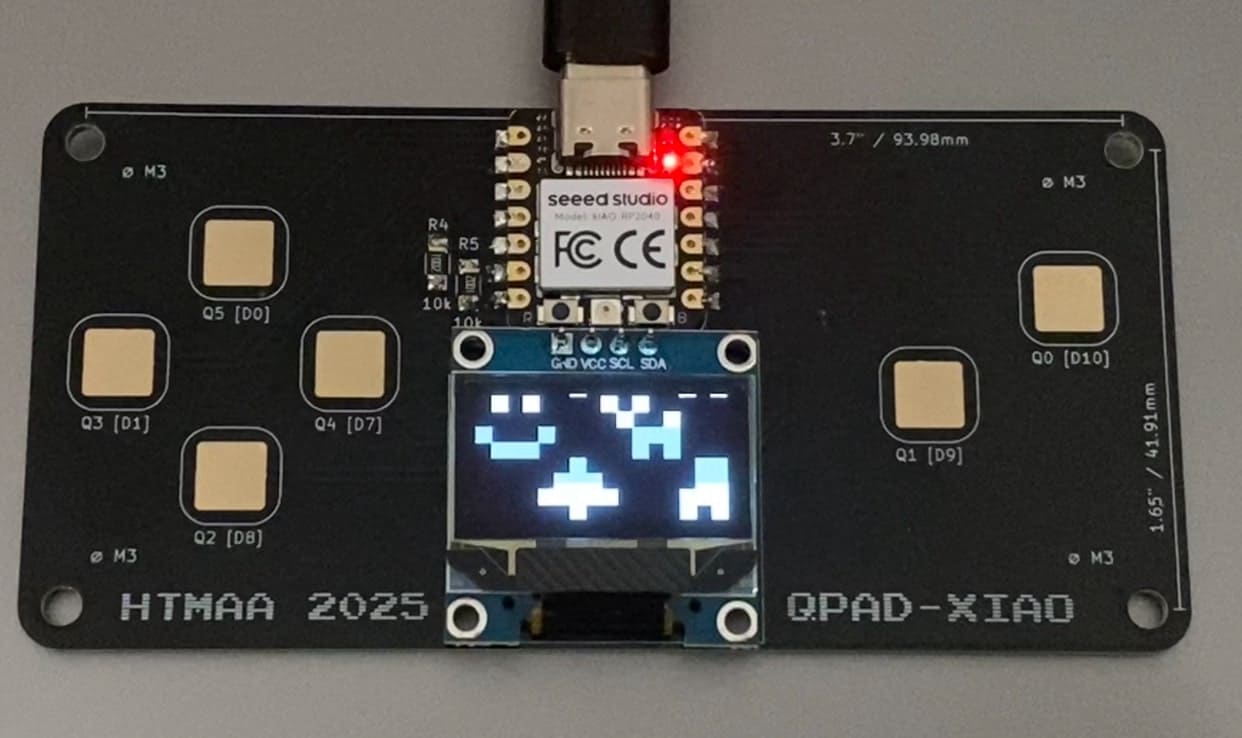
I fixed this and then had some friends try making their own designs. I also added a loading screen which included the controls. It felt cleaner this way. Here is the pixel_artboard_refined.ino file. I tried for a long while to add a way to save the image (which I got help for from ChatGPT), but it was really difficult since the Serial Monitor continued after the image information was sent through the serial port to the Arduino IDE. I condensed my phrasing to fit on the screen and got practice using "display" in the Arduino IDE though which was useful. Supposedly, in order to access the saved file, I needed to open the Serial Monitor (Arduino IDE → Tools → Serial Monitor) and make sure the baud rate matched the code (115200), then copy everything from the P1 line down through the last row of numbers. Following this, I would need to paste that into a text file and save it as something like drawing.pbm. On a Mac in my case, I brew installed imagemagick (by typing the following into the terminal: brew install imagemagick) in order to convert to a jpg using "convert drawing.pbm drawing.jpg" again in the terminal. This didn't work though, and I opted to leave figuring out the saving functionality for another day. Here is the loading screen figured out.
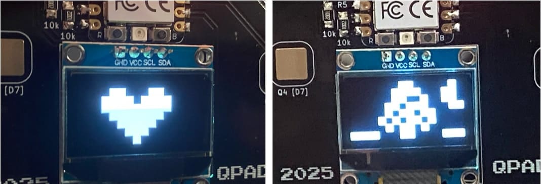
Here are a few of the artworks.
Up next was the group assignment where we were meant to demonstrate and compare the toolchains and development workflows for available embedded architectures. I will admit I had to ask ChatGPT what that meant (see chat linked previously). Dimitar and I met up to go through this together and have documented our toolchain, development workflow, and embedded architecture comparisons here. I had a lot of fun this week revisiting soldering and Arduino coding with a much better foundation than I had the last time I did these things. I plan to review the HTMAA page for this week quite a bit as I do some more exploration on my own.