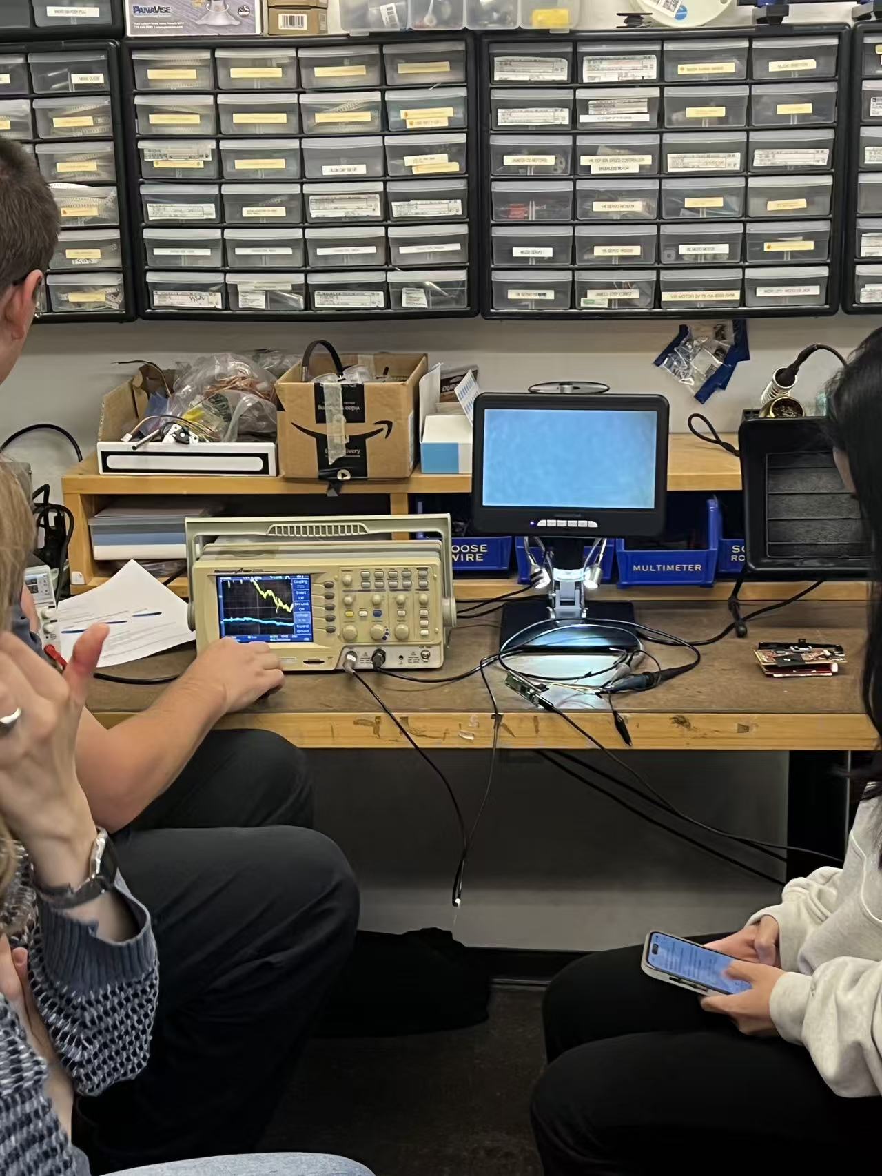
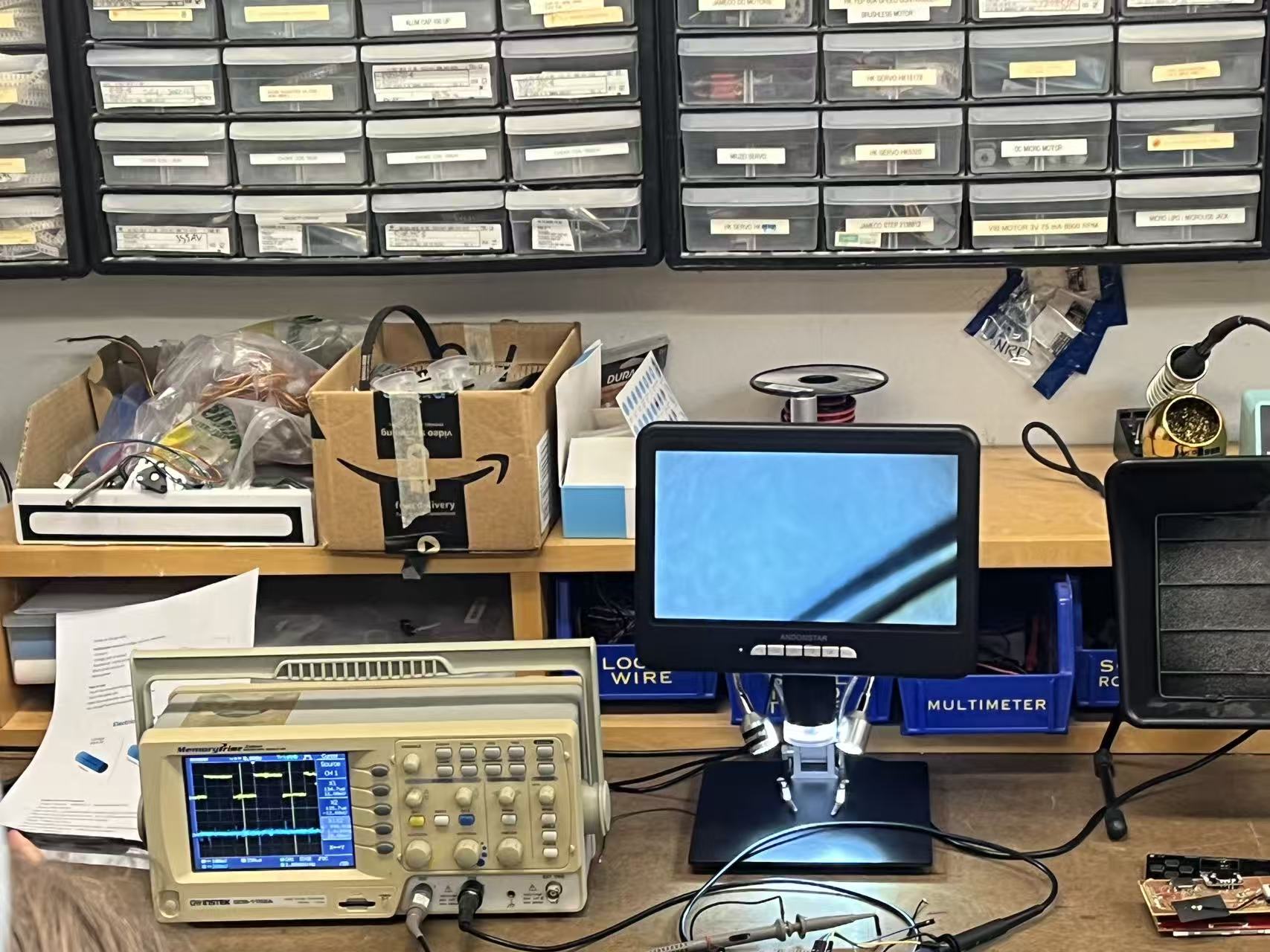
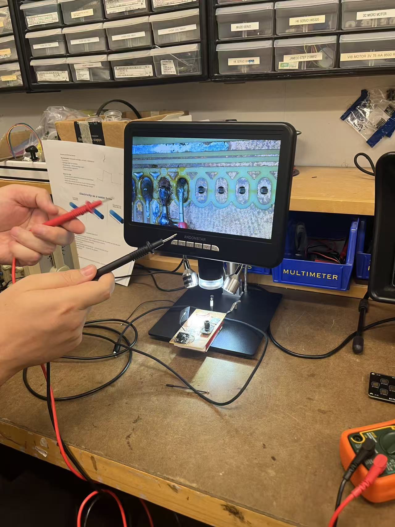
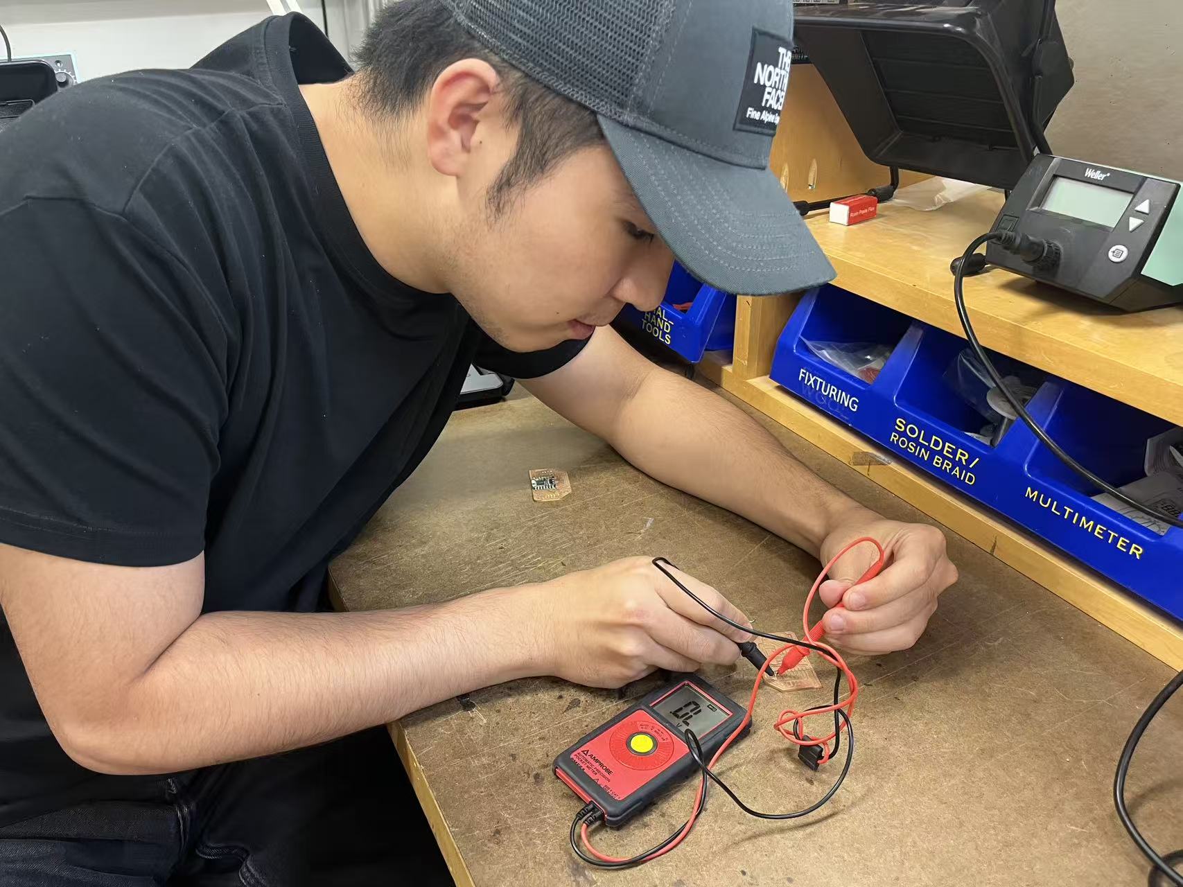
Group assignment. As a group we set up the electronics bench with a power supply, oscilloscope, and a dev board. We powered the board, probed GPIO and power rails, and used the scope to confirm reset behavior and I/O timing. We also checked button debouncing and LED drive current to understand the basic I/O characteristics before designing our own boards.
Group assignment
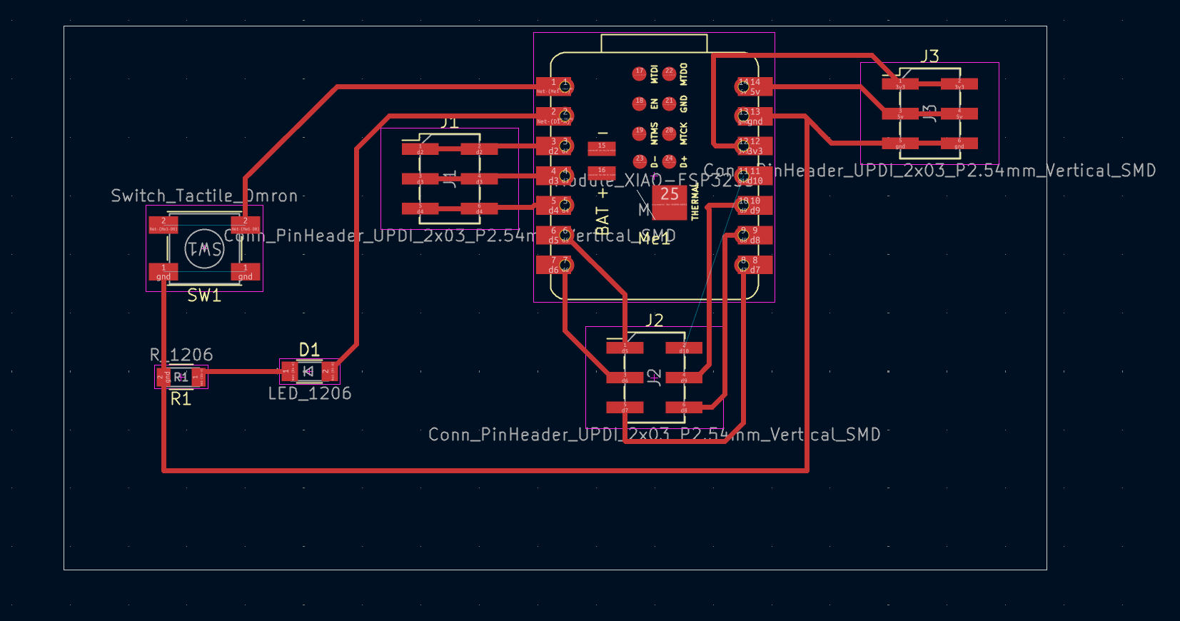
Individual assignment — designing my own board
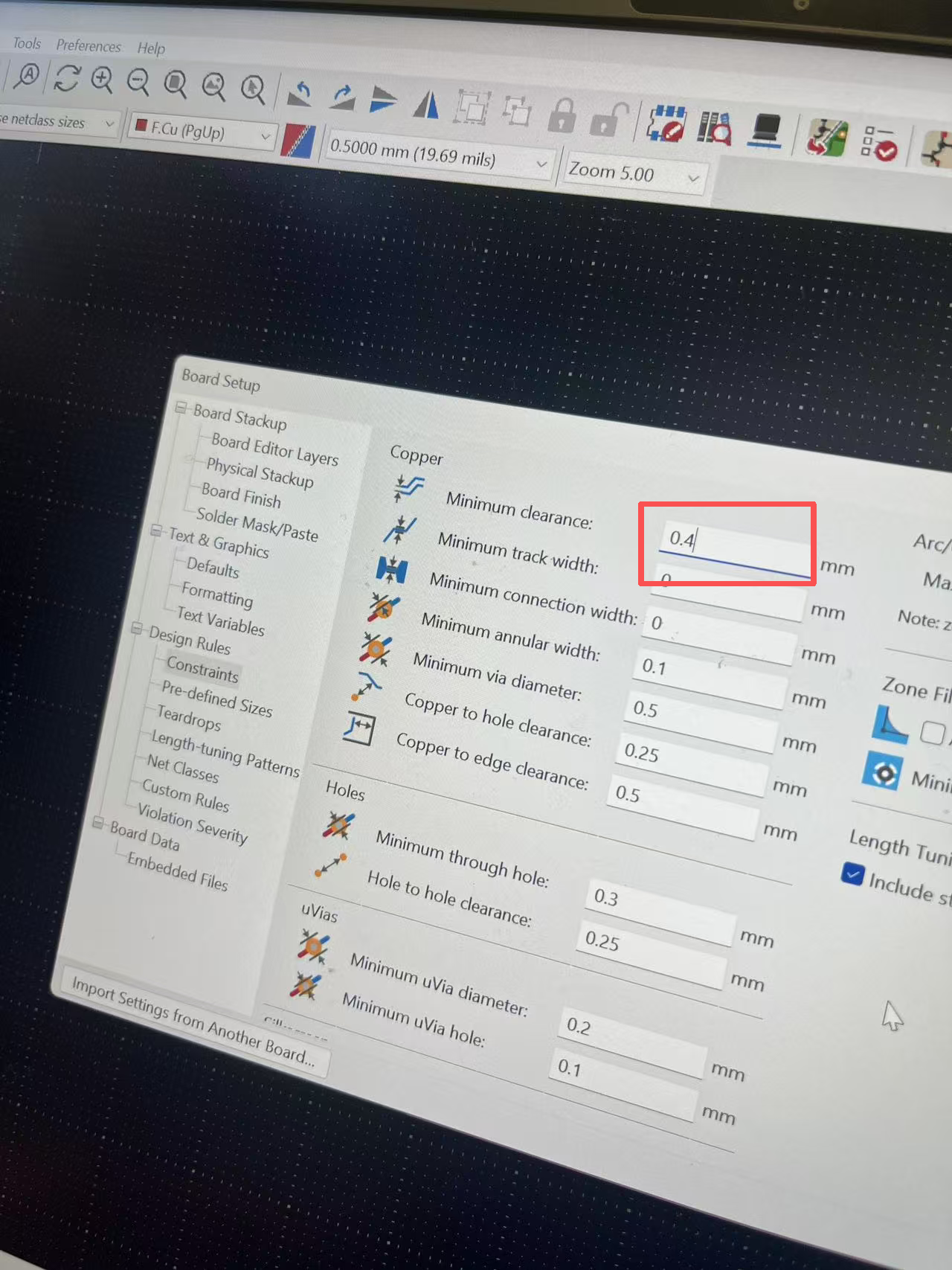
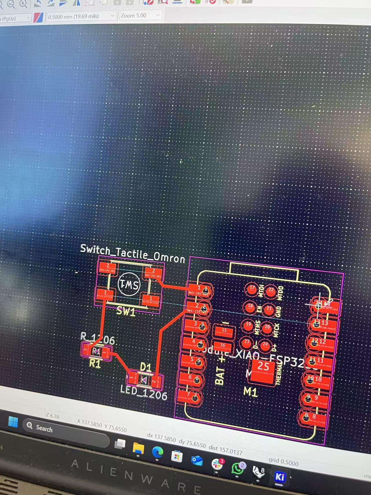
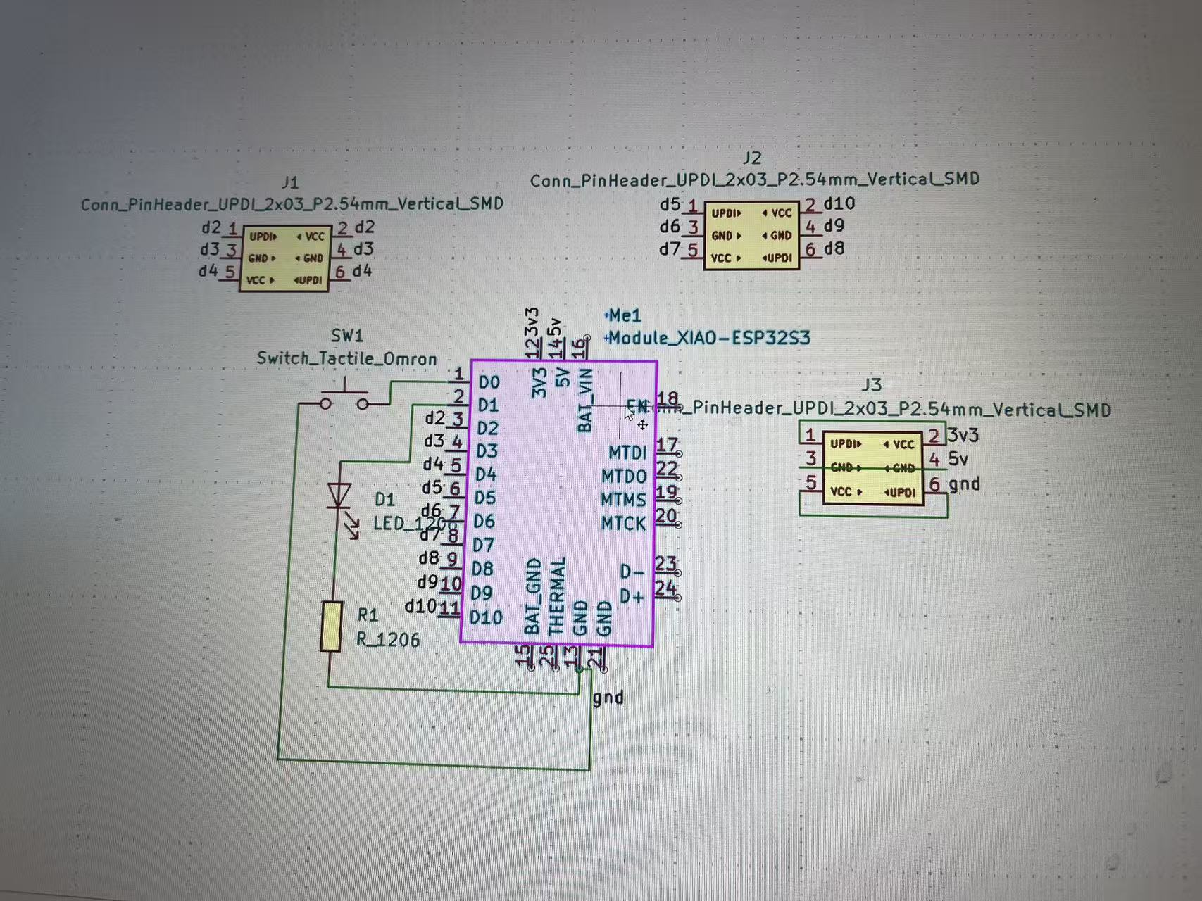
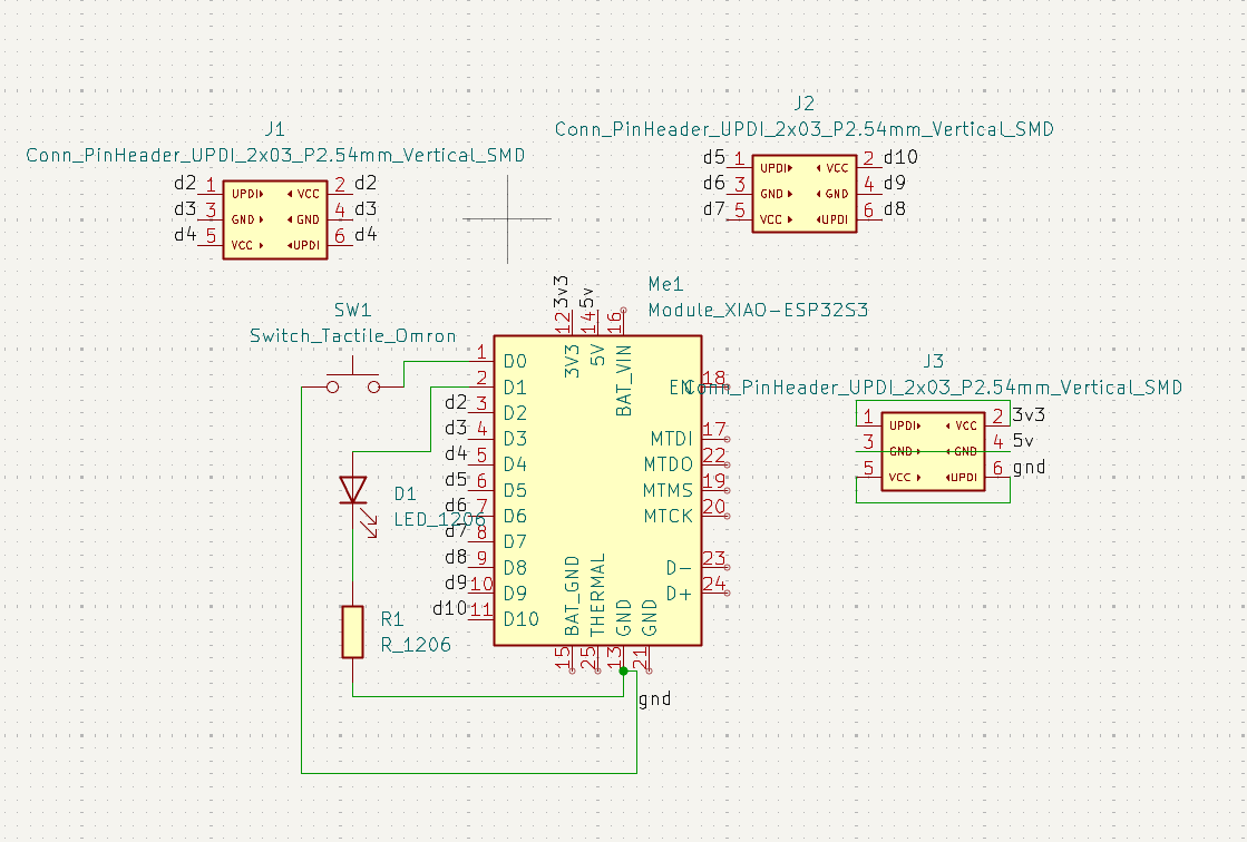
For the individual part, I designed a small embedded board in an EDA tool using inventory parts. I sketched the schematic, assigned footprints, and routed the PCB with the fab’s design rules (trace/space, hole sizes, clearances). Finally, I simulated the logic in Wokwi: a pull-up button on D0 drives an LED on D1, so I could confirm the basic behavior before milling the board.
MCU choice — Seeed XIAO ESP32-S3
I selected the Seeed XIAO ESP32-S3 because I plan to put this project online later. Following Anthony’s advice, the ESP32-S3 gives:
- Reliable 2.4 GHz Wi-Fi and Bluetooth in a tiny footprint.
- Native USB for easy flashing, logging, and power.
- Enough GPIO for LED, button, and future sensors.
- Room for OTA updates or cloud logging without a hardware redesign.
Simulation code (Wokwi)
// Simple button → LED test
const int LED_PIN = D1;
const int BTN_PIN = D0;

void setup() {
  Serial.begin(115200);
  pinMode(LED_PIN, OUTPUT);
  pinMode(BTN_PIN, INPUT_PULLUP); // button to GND
}

void loop() {
  int pressed = (digitalRead(BTN_PIN) == LOW); // active-low
  digitalWrite(LED_PIN, pressed ? HIGH : LOW);
}
Board files (.zip): Download 10.3.zip