This week I focused on input devices: as a group we probed an existing motion-sensor board with an oscilloscope, and individually I connected a PIR sensor to my own board and read it from firmware. The goal was to see real analog/digital behavior on the scope, then close the loop with code running on my microcontroller.
Assignments
- Group: probe an input device’s analog levels and digital signals.
- Individual: measure something — add a sensor to a microcontroller board I designed, and read it.
Group assignment (1–3)
We used the oscilloscope to examine a motion-sensor board. Following the clock line helped us understand the timing; we also probed several random GPIO/test pads. Some pins showed noticeably higher switching frequencies than others, which suggested different sub-circuits (clocked logic vs. slow I/O or interrupts). It was a fast way to “reverse read” behavior without having the full schematic.
Individual assignment (4–11)
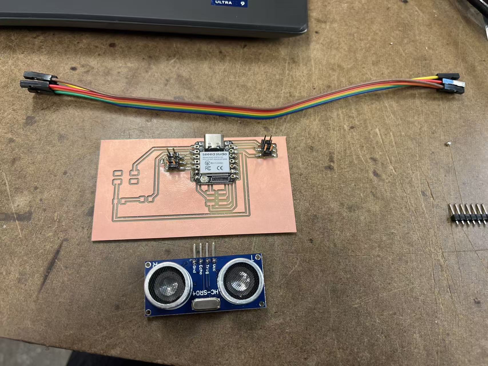
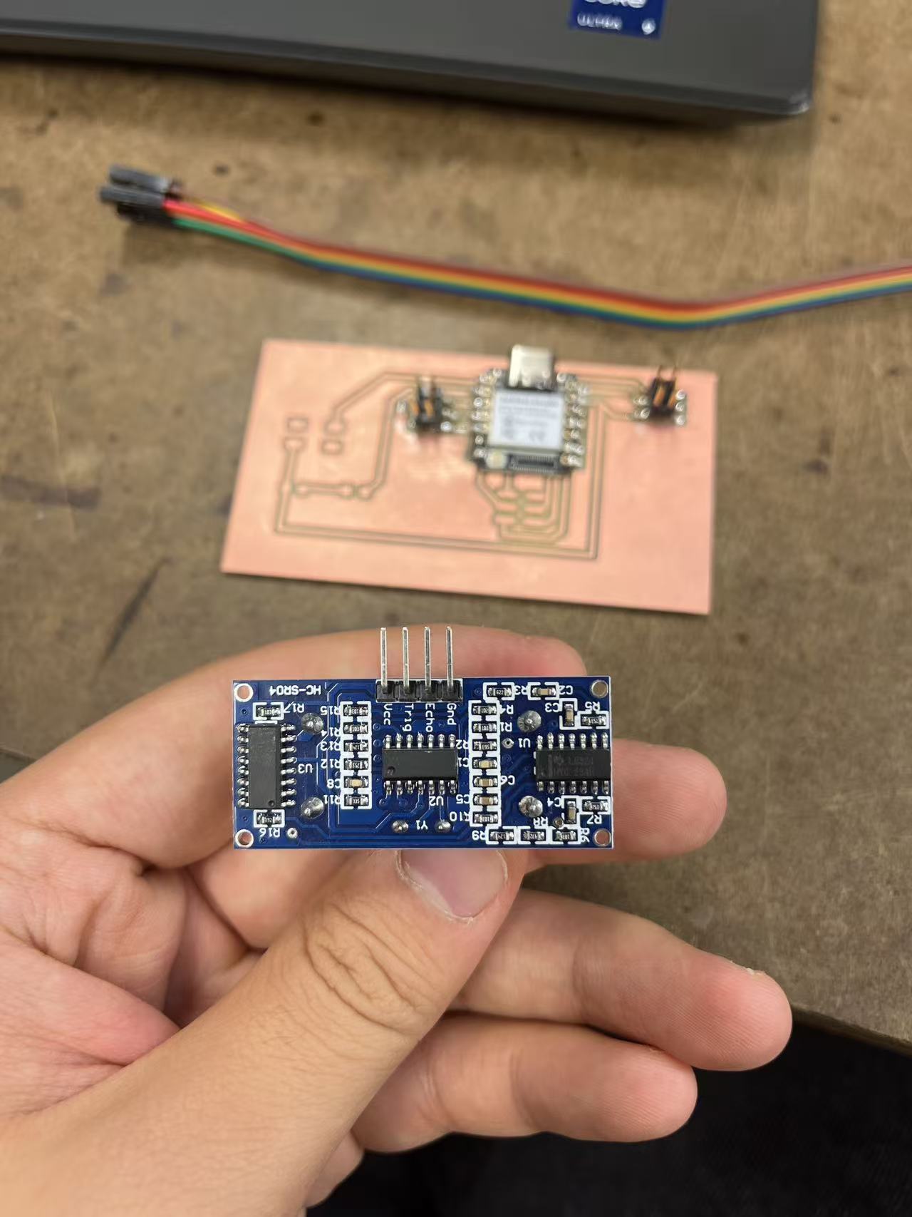
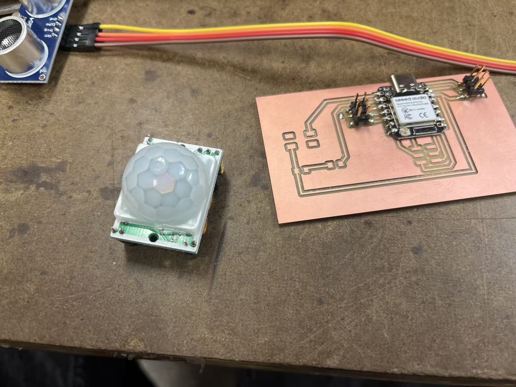
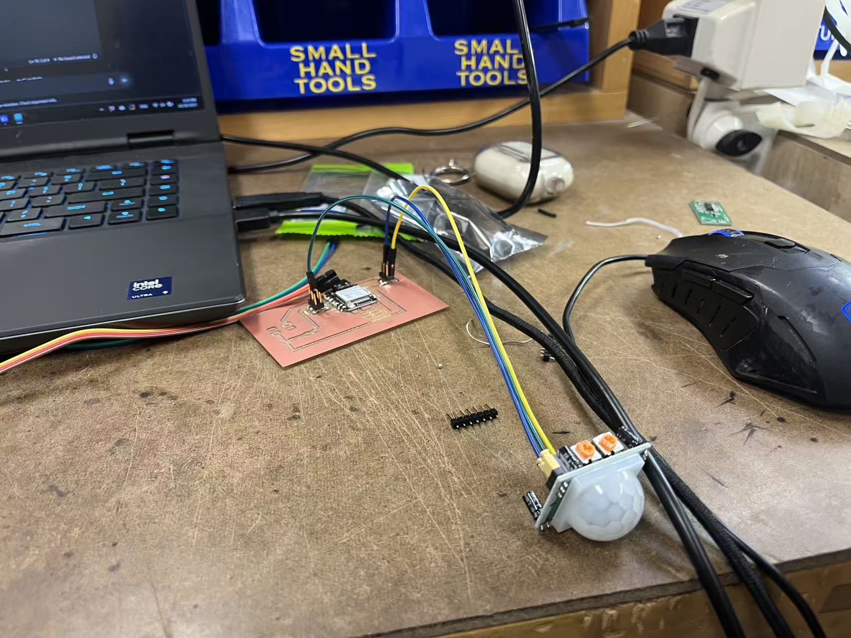
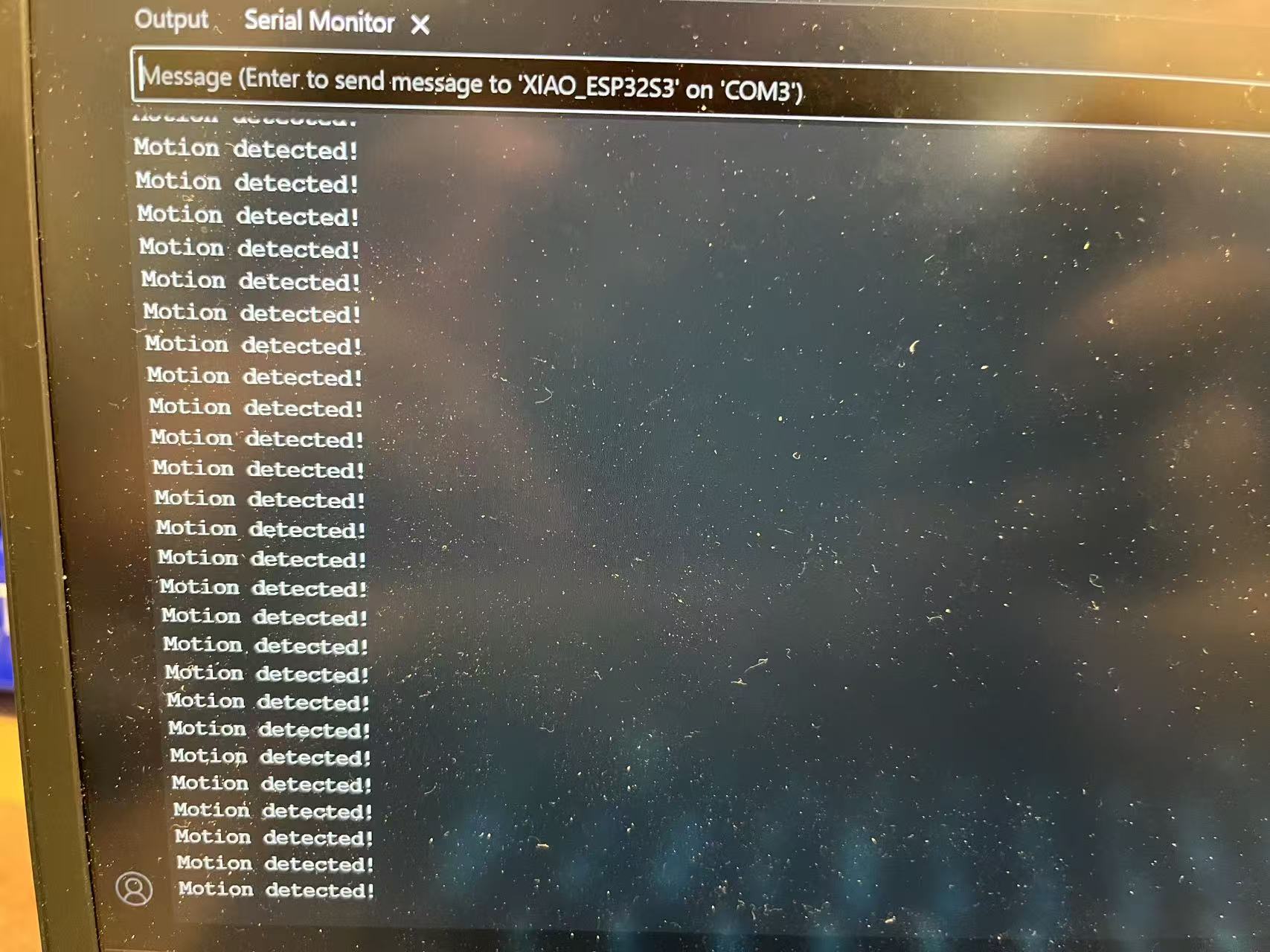
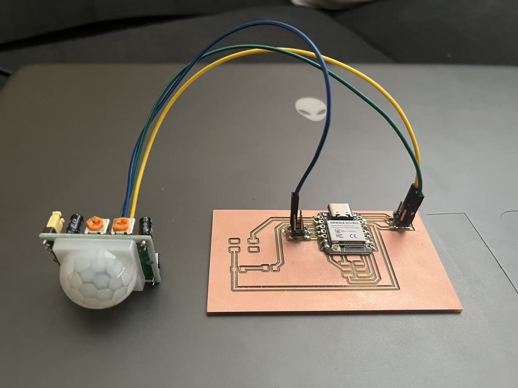
For the individual part, I connected a PIR motion sensor to my own board and read it from firmware. I first checked the sensor on a milled test board, inspected solder joints, and then wired the signal to the MCU headers. After validating power and I/O levels, I logged the readings over serial and confirmed responsiveness by waving my hand in front of the sensor.
Firmware — PIR motion test
I tested the PIR sensor with a simple sketch. I haven’t soldered the LED yet, so the program
uses the Serial monitor (115200 baud) for feedback; the LED pin is already defined and
will light once the LED is added. Wiring used: PIR signal → D2, PIR VCC →
3V3, PIR GND → GND.
const int PIR = D2;
const int LED = D3;

void setup() {
  Serial.begin(115200);
  pinMode(PIR, INPUT);
  pinMode(LED, OUTPUT);
  Serial.println("PIR sensor test start...");
}

void loop() {
  int motion = digitalRead(PIR);
  if (motion == HIGH) {
    Serial.println("Motion detected!");
    digitalWrite(LED, HIGH);   // LED will work after it’s soldered
  } else {
    Serial.println("No motion");
    digitalWrite(LED, LOW);
  }
  delay(500);
}