SmartPi Agentic Assistant
Overview
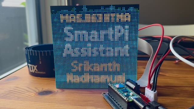
The idea of the SmartPi Assistant is a desktop device that highlights important events to improve the productivity of busy people. Often we are deluged by emails, slack messages, meetings etc. and it would be nice if a LLM could process these huge information sources and summarize them as actionable inputs through a simple device sitting on your desk or bedside.
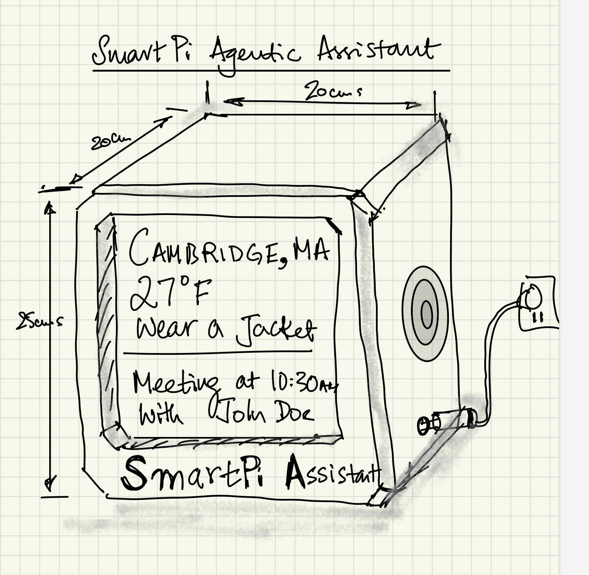
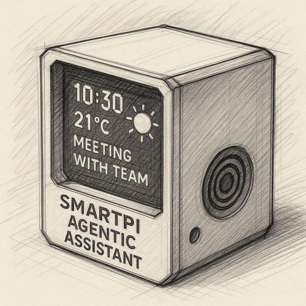
SmartPi Agentic Assistant is a compact, low-power personal assistant built on the Raspberry Pi Pico W, using large language models (LLMs) to convert raw digital data — from your calendar, email, weather feeds, or news sources — into concise text for a 64×64 display, and natural speech via a small speaker. We could also have a microphone on the SmartPi Assistant so we ask the Assistant to perform specific tasks - this pull mode can be quite useful to request for specific tasks.
It bridges the physical world of sensors, displays, and sound with the reasoning power of LLMs, creating a modular platform for context-aware, ambient intelligence at the edge.
System Design
The SmartPi Assistant
SmartPi Embedded Controller Design
The SmartPi Assistant is an embedded interactive device built around the Raspberry Pi Pico W microcontroller. It integrates a LED matrix panel as the primary visual display, a 3–4 Ω speaker for audio output, and an Adafruit MAX98357 amplifier to drive the speaker with clear sound. The design also accommodates an Adafruit ICS-43434 digital I²S MEMS microphone for capturing voice commands, enabling natural, voice-based interaction. Together, these components form a compact, low-power system capable of displaying dynamic information, responding to spoken inputs, and communicating wirelessly through the Pico W's built-in Wi-Fi—making it a versatile platform for experimenting with edge AI, local sensing, and responsive embedded control.
Why Raspberry Pi Pico W?
The Raspberry Pi Pico W is an ideal choice for the SmartPi Embedded Controller because it combines affordability, performance, and built-in wireless connectivity in a compact form factor. Powered by the RP2040 dual-core ARM Cortex-M0+ processor, it provides sufficient computational power for real-time sensor data acquisition, control logic, and lightweight edge AI tasks, while maintaining low power consumption—critical for continuous operation in field environments. Its Wi-Fi capability enables seamless integration with cloud or local networks for data exchange and remote updates, eliminating the need for external modules. Additionally, the Pico W's rich GPIO interface, extensive community support, and compatibility with MicroPython and C/C++ SDKs make it both versatile and developer-friendly, ensuring rapid prototyping and reliable deployment.
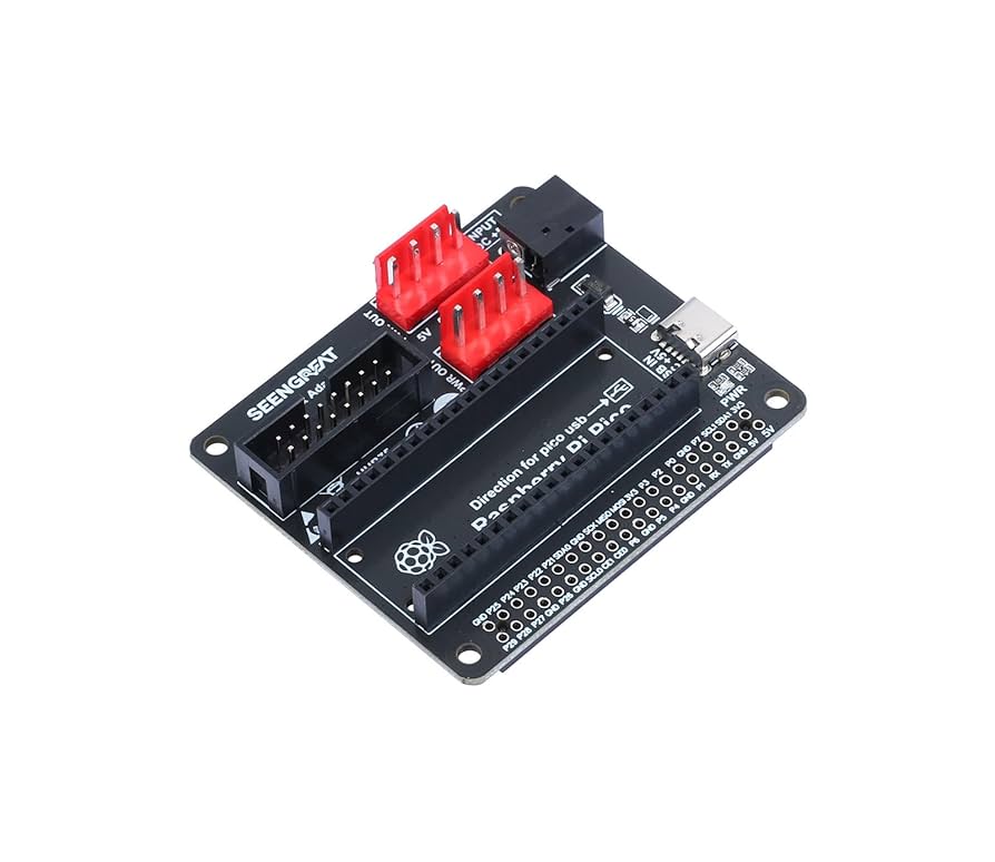
Display Interface: HUB75 LED Matrix Connection
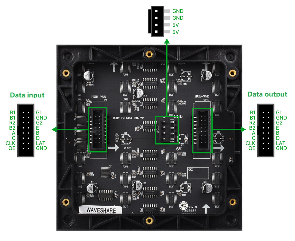
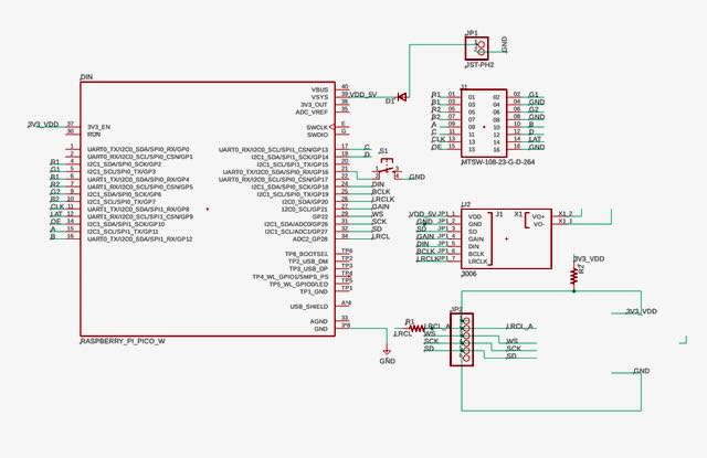
The HUB75 (2×8) connector serves as the standard interface between the Raspberry Pi Pico W and the 64×64 RGB LED matrix panel. It provides a set of 16 data and control lines, including color data inputs (R, G, B), row address lines, latch, clock, and output enable signals, which together allow precise control of the timing and brightness of individual LEDs. The HUB75 interface does not carry any intelligence—it simply maps the Pico's GPIO outputs directly to the LED driver circuitry on the panel. Because the display requires rapid and synchronized data updates to render smooth animations and text, the HUB75 connector offers a convenient and electrically robust way to handle high-speed parallel communication. Using this standardized interface simplifies wiring, ensures compatibility with a wide range of LED panels, and allows the SmartPi Assistant to produce dynamic visual feedback efficiently from the Pico W.
Connection Between Raspberry Pi Pico W and HUB75 Display Interface
The Raspberry Pi Pico W interfaces with the 64×64 RGB LED matrix through a 2×8 HUB75-style header (MTSW-108-23-G-D-264), which provides a standardized set of data, address, and control signals to drive the LED rows. The HUB75 connector carries the color data lines for both the upper and lower halves of the display (R1, G1, B1, R2, G2, B2), four row address lines (A–D), and three control signals: CLK (clock), LAT (latch), and OE (output enable). Three ground pins (at positions 4, 8, and 16) complete the interface. Power for the LED panel is provided separately via its dedicated 5 V, high-current 2-pin connector, and the Pico's ground must be shared with the panel's ground to ensure proper signal referencing.
The complete pin mapping between the Raspberry Pi Pico W and the HUB75 connector is shown in the table below:
| Pico Pin # | Pico GPIO | HUB75 Pin # | HUB75 Signal | Description |
|---|---|---|---|---|
| 4 | GP2 | 1 | R1 | Upper half red data |
| 5 | GP3 | 2 | G1 | Upper half green data |
| 6 | GP4 | 3 | B1 | Upper half blue data |
| 8 | GND | 4 | GND | Ground |
| 7 | GP5 | 5 | R2 | Lower half red data |
| 9 | GP6 | 6 | G2 | Lower half green data |
| 10 | GP7 | 7 | B2 | Lower half blue data |
| — | — | 8 | GND | Ground |
| 15 | GP11 | 9 | A | Row address bit 0 |
| 16 | GP12 | 10 | B | Row address bit 1 |
| 17 | GP13 | 11 | C | Row address bit 2 |
| 19 | GP14 | 12 | D | Row address bit 3 |
| 11 | GP8 | 13 | CLK | Pixel clock (shift register clock) |
| 12 | GP9 | 14 | LAT | Latch (strobe) |
| 14 | GP10 | 15 | OE | Output enable (active-low blanking) |
| — | — | 16 | GND | Ground |
Good PCB layout practice includes placing multiple ground vias near the header and maintaining a solid ground pour under the signal traces to minimize skew and EMI.
SmartPi Hardware Implementation Details
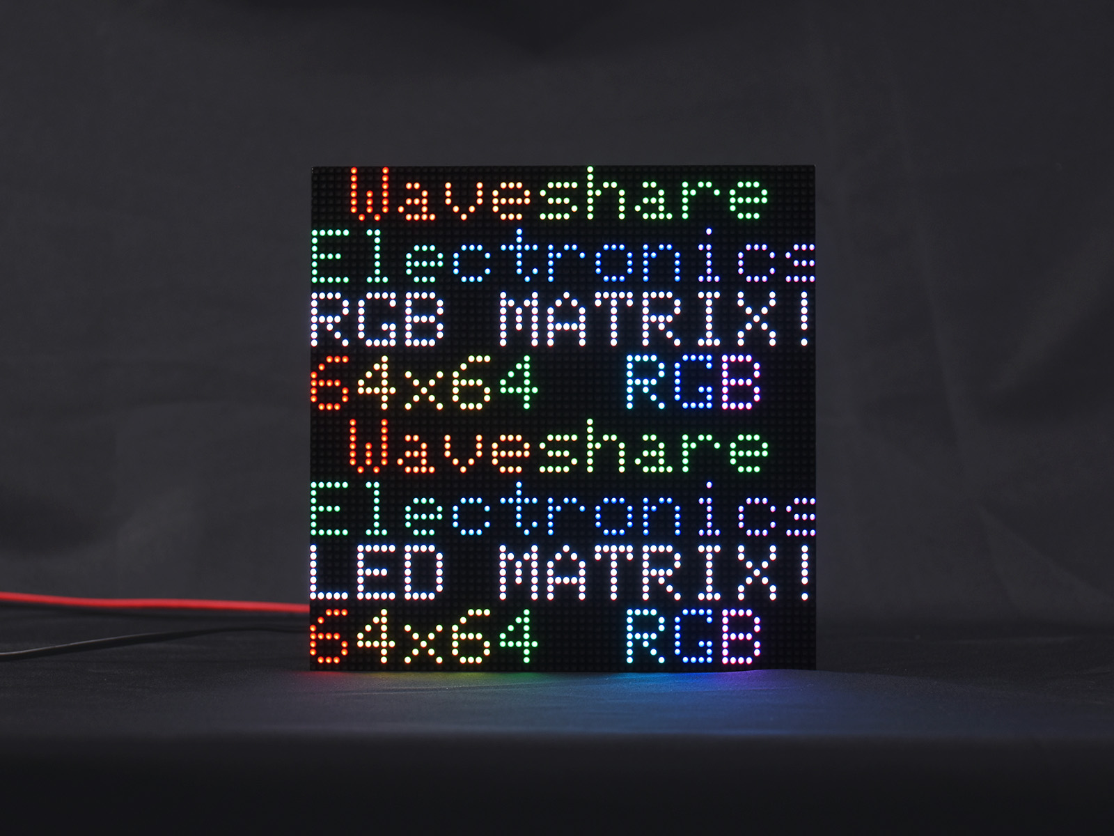
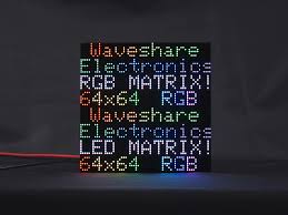
- I procured a 6RGB full-color LED matrix panel, with 64x64 pixels and 2mm Pitch. From Waveshare.com. These are modular pieces that can be daisy chained together to create larger LED matrices. I liked the idea of modular expandable components.
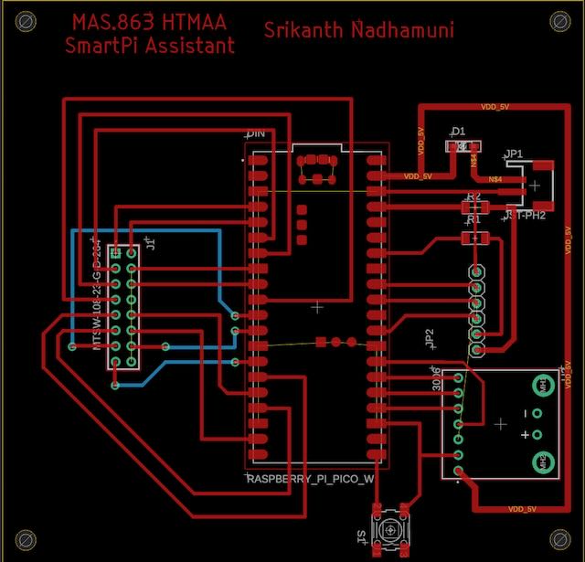
- I designed a PCB board to interface the above LED matrix panel with Raspberry Pi Pico W with HUB75 standard socket
- Created the traces in the layout view with the following
There were some crossover issues after the manual trace layout, so dealt with a couple of crossovers using zero ohm resistors as bridges. There were 3 more that I had to deal with. So instead of option for a 2 sided board (and the more involved milling process), I discussed with Anthony and came up with making 3 holes through which we'd run wires and connect the HUB75 CLK, LAT and OE pins from the back of the board, using header pins on the Raspberry Pi Pico.
Added a JST for power and a switch to turn the device on/off.
- Created a Eagle 9.x compatible board file with a .brd extension from AutoCAD fusion. Loaded the .brd file on the Bantam software connected to the OtherMill(creative name!!) milling machine.
- Took a single sided board and taped it up using a double sided tape, making sure there are no overlaps (will mess up the milling if the board is uneven)
- Loaded the 1/64 mill bit and started milling the .brd file
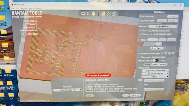
- Clicked "Mill All Visible" with the 1/64" mill bit, to mill the finer portions of the PCB board.
- After the fine milling, loaded the 1/32" larger mill bit, and started the fast milling of the larger board
- After completing all the traces, had to pick the holes and outline to cut using the 1/32" mill bit.
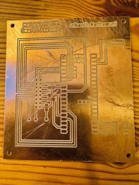
- After all this found that the board was not complete, it was missing the right side of the Raspberry Pi Pico pins and the power points and most importantly the text with course name!!
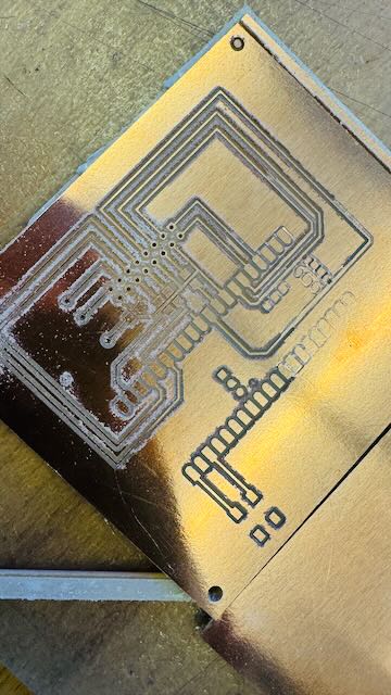
- Anthony, exported a .gerber file and loaded its constituent parts for the trace, holes and outline, and restarted the job, and lo and behold:
- This time the milling machine completed the entire board with all the pins, traces, holes and outline and importantly the text with the course and my name on it, except for the JST power pins, which was no big deal, so we took it for done.
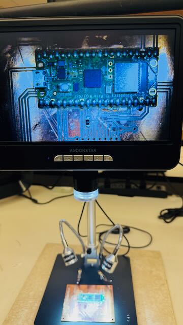
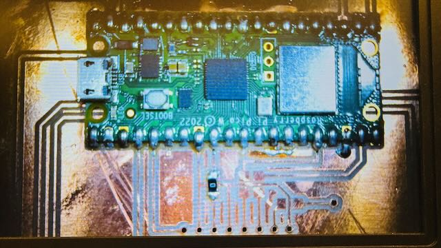
- Started soldering the Raspberry Pi Pico W onto the newly printed PCB. The adonstar digital magnifier was super useful in placing the RP Pico W precisely on the correct position on the board, such that the tiny copper pads created by the layout tool was centered correctly.
- Cleaned my soldering iron with a small amount of soldering lead to get good flow, then put a blob of solder lead on the bottom left pin and holding the RP Pico W down applied the soldering iron and got one pin securely fastened. After that it was just a matter of getting the rest going.
The digital magnifier was not actually useful to solder, it helped to look directly at the components, but it helped in inspecting the solders and ensure there were no bridges between pins.
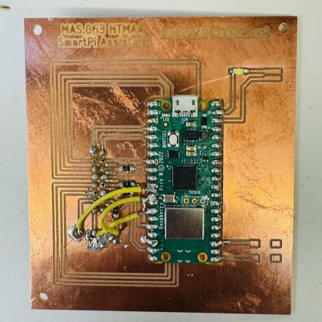
- Then proceeded to solder the zero ohm resistors, which were super tiny and difficult to keep in place as the soldering iron and lead came close, it would move and get soldered in weird angles, one needed to heat the trace pad again and ever so slightly move it back into place - this was challenging. But got all 3 zero ohm resistor soldered in place to bridge underlying traces. Test connectivity of the resistors as well as the underlying trace which it was bridging over. All was fine.
- Finally got the diode from the external 5V Vcc point to the VSYS (pin 39) soldered ensuring that the tiny (barely visible) arrow mark was in the correct direction. Added the 3 wires that were needed to avoid the trace crossover challenges.
Lessons Learned: Multiple Errors in the PCB Design
Despite careful planning, several critical mistakes emerged during the PCB fabrication and assembly process that prevented the board from functioning correctly. These errors provided valuable learning experiences about PCB design considerations and the importance of thinking through physical constraints early in the design process.
1. Inverted HUB75 Connector Placement
Since I did not have a female HUB75 connector component in the lab, I had to make the HUB75 connector using header pins. Due to the single-sided PCB board, I was forced to solder the header pins on the milled side of the PCB, with the connector header pins sticking out at the bottom (on the back side of the PCB board). This resulted in basically wrong (inverted) connections driving the HUB75 ribbon to the display matrix.
This orientation issue meant that the signal mapping from the Raspberry Pi Pico GPIO pins to the LED matrix was completely reversed, making it impossible to display anything correctly without rewiring or using an adapter board.
2. Missing Power Supply for the LED Matrix
The LED matrix needs a 5V power supply with high current capacity—it cannot be driven by the small current capacity of the Raspberry Pi Pico W. I made no provisions to drive the display board, besides powering the Raspberry Pi Pico W itself. This was yet another rookie mistake.
A 64×64 RGB LED matrix can draw several amps of current when displaying bright, full-screen images. The Pico W's 5V pin can only source a few hundred milliamps at most, which is far insufficient. A proper design would have included a dedicated 5V, high-current power input (such as a barrel jack or JST connector) connected directly to the LED matrix panel's power pins, with only signal-level connections going through the Pico.
3. Poor USB Connector Accessibility
By placing the Raspberry Pi Pico W in the middle of the PCB board, I made it hard to insert the micro USB port provided on top of the RP Pico board. I should have designed the board such that the RP Pico W would be at the top edge of the board, making it easy to connect the micro-USB cable for programming and power.
This seemingly minor oversight created significant practical problems during development and testing, requiring awkward cable angles and making it difficult to access the BOOTSEL button for firmware updates.
Key Takeaways
- Connector orientation matters: Always verify that through-hole connectors will mate correctly with their counterpart cables, considering which side of the board they'll be soldered to.
- Power budget planning: Calculate the maximum current draw of all components early in the design and provision adequate power supply connections.
- Physical accessibility: Place connectors and buttons that need frequent access near the board edges, away from other components that might obstruct them.
- Prototype early: These mistakes could have been caught with a simple cardboard mockup or 3D-printed test fixture before committing to PCB fabrication.
Trip to India and Time to Derisk the Project
I needed to go to India for 10days for a meeting and event. I knew that the PCB still had the power connections and switch to be connected and the HUB75 pins to be tested. It was unlikely all this was going to work in a day. Then there was the learning about the software environment and then developing the software to test the LED matrix board.
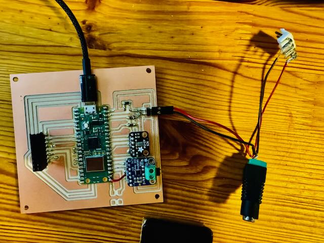
I decided that I would de-risk the project by using a pre-fabricated RGB Matrix Adapter Board, which I had bought when I ordered the Matrix Board itself. Decided to use the adapter to interface the Raspberry Pi Pico W to the RGB Matrix. This was a life saver.
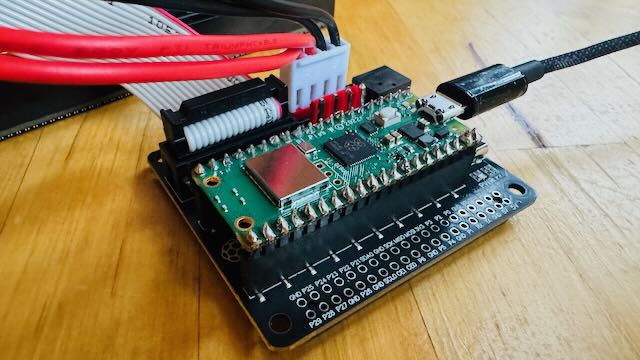
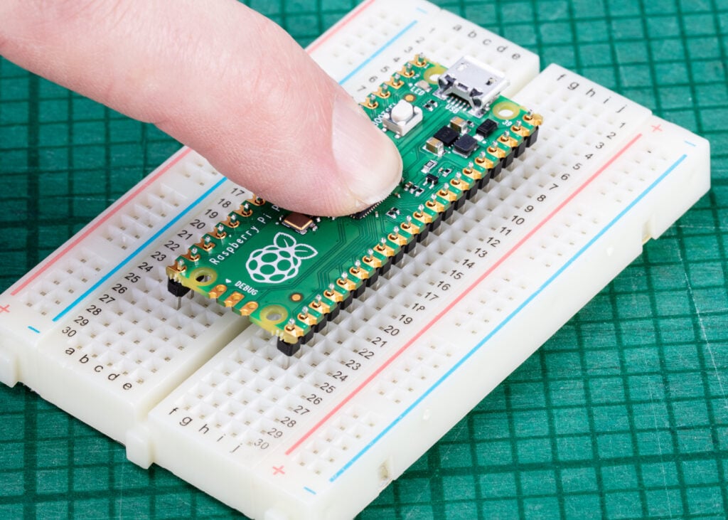
- Installing header pins to the Raspberry Pi Pico so it could be fit into the Adapter board.
- Pushed the RP Pico W with header pins into the adapter board and connected the a the HUB75 ribbon connector and power supply JST connector
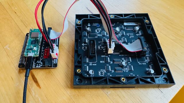
- Connected the adapter card to the RGB Matrix
- Connected the micro USB cable into the raspberry Pi Pico and the other end to my Macbook.
Setting up the Raspberry Pi Pico with CircuitPython Environment
I decided to use CircuitPython on the RP Pico, using the Mu Editor, here are the setup instructions:
- Downloaded the CircuitPython UF2 file.
- I held down the BOOTSEL button, then plugged the Pico into a USB port on my macbook.
- Release the BOOTSEL button after connecting the Pico.
- It will install as a mass storage device named "RPI-RP2".
- Drag and drop the CircuitPython UF2 file onto the "RPI-RP2" volume. The Pico will reboot, a new disk drive will appear named CIRCUITPY, and you're done flashing.
- There will be a default code.py file in the new disk drive, you open it with Mu Editor, and the content in it is: "print("Hello World!")", the specific opening steps are shown in the last figure.
Loaded a Test Program
import board
import displayio
import framebufferio
import rgbmatrix
import time

# Always release any existing display before (re)initializing
displayio.release_displays()

# --- HUB75 + Seengreat Pico adapter pin map ---
rgb_pins = [board.GP2, board.GP3, board.GP4,   # R1, G1, B1
            board.GP5, board.GP8, board.GP9]   # R2, G2, B2
addr_pins = [board.GP10, board.GP16, board.GP18, board.GP20, board.GP22]  # A,B,C,D,E
clock_pin = board.GP11
latch_pin = board.GP12
oe_pin     = board.GP13

WIDTH = 64
HEIGHT = 64

matrix = rgbmatrix.RGBMatrix(
    width=WIDTH, height=HEIGHT, bit_depth=5,  # bit_depth 4–6 is a good starting point
    rgb_pins=rgb_pins,
    addr_pins=addr_pins,
    clock_pin=clock_pin,
    latch_pin=latch_pin,
    output_enable_pin=oe_pin,
    tile=1, serpentine=False, doublebuffer=True
)

display = framebufferio.FramebufferDisplay(matrix, auto_refresh=True)

# Create a 1-color full-screen bitmap we can recolor quickly
palette = displayio.Palette(1)
bitmap = displayio.Bitmap(WIDTH, HEIGHT, 1)
tg = displayio.TileGrid(bitmap, pixel_shader=palette)
group = displayio.Group()
group.append(tg)
display.root_group = group

def fill(rgb_hex):
    palette[0] = rgb_hex
    # bitmap already all index 0, so changing palette updates whole screen
    time.sleep(0.5)

while True:
    fill(0xFF0000)  # red
    fill(0x00FF00)  # green
    fill(0x0000FF)  # blue
    fill(0xFFFFFF)  # white (brief)
    fill(0x000000)  # black (off)
The Test program worked!!
SmartPi Enhancement: Adding Voice Interaction Capabilities
Following the insights gained from the MAS.863 classes on input devices and output devices, I recognized an opportunity to significantly enhance the SmartPi Assistant's functionality by adding bidirectional audio capabilities. While the initial design focused solely on visual output through the LED matrix—operating in a "push" model where the n8n cloud server unilaterally displays information—the addition of audio I/O transforms the device into a truly interactive assistant.
This enhancement enables two critical capabilities:
- Audio Output (Speaker): The system can now vocalize displayed messages, making the assistant accessible in situations where visual attention isn't possible—such as while cooking, exercising, or working with your hands. This adds a multi-modal output dimension that significantly improves the user experience.
- Audio Input (Microphone): By adding voice input, the SmartPi shifts from a purely passive display to an interactive assistant supporting a "pull" model. Users can issue specific requests ("What's my next meeting?", "What's the weather?"), which are processed locally and then forwarded to the n8n server for LLM-based interpretation and response.
For the audio subsystem, I chose to implement a fully digital audio path using the I²S (Inter-IC Sound) protocol. This decision offers several advantages over traditional analog solutions: I²S eliminates the need for external analog-to-digital (ADC) or digital-to-analog (DAC) converters on the microcontroller side, reduces susceptibility to electrical noise and ground loops, simplifies PCB routing by using digital logic levels, and ensures bit-perfect audio transmission between the Pico W and the audio peripherals. The I²S standard is well-supported in embedded audio applications and provides a clean, standardized interface that integrates seamlessly with the RP2040's PIO (Programmable I/O) subsystem.
Audio Output: Adafruit MAX98357 I²S Amplifier
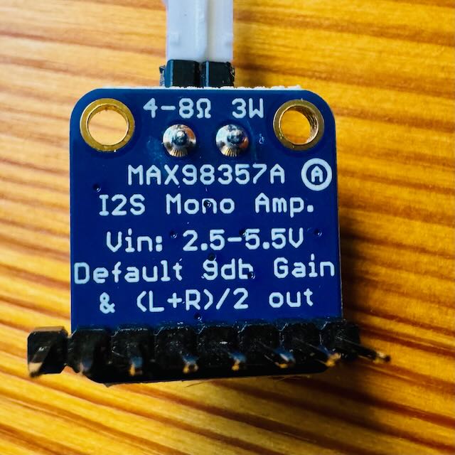
The Adafruit MAX98357 is a digital-to-analog Class-D audio amplifier designed to convert digital audio signals (I²S) into high-quality analog sound capable of driving a speaker directly. The Raspberry Pi Pico W itself lacks both a digital-to-analog converter (DAC) and sufficient output power to drive a low-impedance speaker—its GPIO pins can only source a few milliamps of current, suitable for logic signals but not for audio. The MAX98357 fills this gap by taking the Pico's I²S digital audio stream, converting it to an amplified analog output, and efficiently delivering up to 3 watts of power to a 3–4 Ω speaker. This makes it ideal for producing clear, audible speech or alert tones in a compact, low-power embedded system like the SmartPi Assistant, without the need for bulky external amplification hardware.
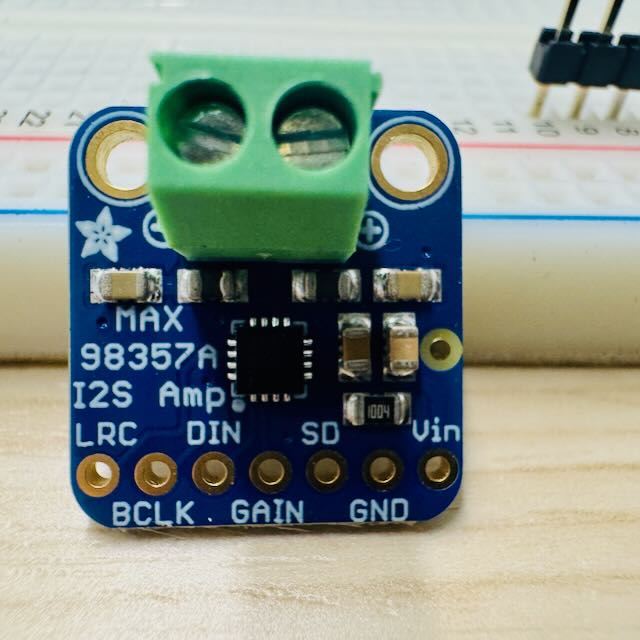
Connecting the MAX98357 to Raspberry Pi Pico W
Purpose: Converts Pico's digital audio (I²S) into amplified analog output for a speaker.
Power: 3 V – 5 V (use 5 V if available).
| MAX98357 Pin | Connect to Pico W | Notes |
|---|---|---|
| VIN | 5 V | Same 5 V supply as LED panel (with shared GND) |
| GND | GND | Common ground with Pico |
| DIN | GP18 | I²S Data Out |
| BCLK | GP19 | I²S Bit Clock |
| LRCLK | GP20 | I²S Left/Right Clock (a.k.a. Word Select) |
| GAIN / SD | Pull-up or GPIO (optional) | Controls shutdown / gain; tie high to enable always-on |
Speaker: Connect the 3–4 Ω speaker to L+ and L- outputs.
✅ This group can be tested independently by playing audio tones or speech from the Pico without connecting the mic.
Audio Input: Adafruit ICS-43434 I²S MEMS Microphone
The Adafruit ICS-43434 is a digital I²S MEMS microphone that captures high-quality audio and outputs it as a clean, noise-free digital signal. Unlike analog microphones, which require external amplification and are prone to interference, the ICS-43434 performs the analog-to-digital conversion internally and transmits audio data directly to the Raspberry Pi Pico W over the I²S interface. This eliminates the need for an external amplifier stage and ensures consistent performance even in electrically noisy environments. The microphone's small form factor and digital output make it ideal for embedded applications such as the SmartPi Assistant, where it provides accurate voice input for commands or speech recognition. By using the ICS-43434, the system gains a reliable, low-power, and high-fidelity audio capture capability that complements the Pico W's digital audio architecture.
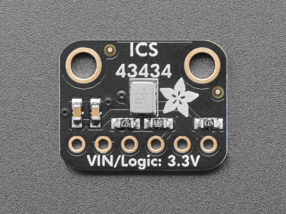
Connecting the ICS-43434 to Raspberry Pi Pico W
Purpose: Captures digital audio directly from sound; sends I²S data to Pico.
Power: 3.3 V only (do not connect to 5 V).
| ICS-43434 Pin | Connect to Pico W | Notes |
|---|---|---|
| 3V3 (VDD) | 3.3 V | Power supply |
| GND | GND | Common ground |
| WS (LRCLK) | GP22 | I²S Left/Right Clock |
| SCK (BCLK) | GP26 | I²S Bit Clock |
| SD (DOUT) | GP27 | I²S Data Output from mic to Pico |
| SEL | GND (or 3V3) | Sets left/right channel (tie to GND for left) |
✅ This group can be tested independently by capturing raw audio samples or displaying waveform data via USB serial.
PCB Design Take 2 with Speaker and Mic
Building upon the lessons learned from the initial PCB design, I started work on an improved version that integrates the audio capabilities directly into the board. This second iteration incorporates both the speaker amplifier and microphone interfaces alongside the existing HUB75 LED matrix connection, creating a more integrated and capable SmartPi platform.
Component Integration
The enhanced PCB design includes the following additions:
- MAX98357 I²S Amplifier: Integrated onto the board and connected to Raspberry Pi Pico W GPIO ports 18–21, providing digital audio output capability with sufficient power to drive a 3–4 Ω speaker directly.
- ICS-43434 I²S MEMS Microphone: Added to the board and connected to RP Pico W GPIO ports 22, 26, 27, and 28, enabling high-quality digital audio input for voice commands and interaction.
Two-Sided PCB Design
The routing complexity increased significantly with the addition of the audio components. After attempting single-sided routing, it became clear that a two-sided PCB board was necessary to accommodate all the connections cleanly. The final layout uses three vias to route HUB75 connections to the bottom layer, minimizing trace crossovers while maintaining signal integrity. This approach provides a cleaner, more manufacturable design compared to using jumper wires or zero-ohm resistors as bridges.
Design Rules and Improvements
Reflecting on the challenges encountered during the first PCB assembly—particularly the difficulty of soldering 16 mil traces with closely-spaced nets and pins—I revised the design rules for improved manufacturability:
- Standard trace width: Increased from 16 mil to 20 mil, making it significantly easier to solder components without bridging adjacent traces.
- Power traces (VBUS/VDD): Widened to 40 mil to ensure adequate current delivery for the DAC amplifier and speaker, reducing voltage drop and improving audio performance.
- 3.3V power traces (3V3_VBUS): Increased to 30 mil for reliable power distribution to digital components.
- Trace spacing: Expanded inter-trace clearance during the milling setup to further simplify hand soldering, taking advantage of the available board real estate.
These design refinements not only improve the physical assembly process but also enhance the electrical characteristics of the board, particularly for the analog audio output path where wider traces reduce impedance and potential interference. The result is a more robust, easier-to-manufacture platform that fully integrates the SmartPi Assistant's display, audio output, and audio input capabilities.
Milling PCB 2
With the improved two-sided PCB design complete, I proceeded to mill and assemble the second-generation SmartPi board. The milling process for the two-sided board required careful alignment and the use of vias to connect traces between the top and bottom layers.
Assembly Process
The assembly of PCB V2 involved several critical steps to ensure proper electrical connectivity and mechanical stability:
- Raspberry Pi Pico W: Soldered the main microcontroller to the board, carefully aligning all 40 pins to their respective pads using the wider 20 mil traces, which made the process significantly easier than the first board.
- MAX98357 DAC Amplifier: Soldered header pins to mount the amplifier module, allowing for easy replacement or testing if needed.
- ICS-43434 Digital Microphone: Soldered header pins to mount the digital microphone breakout board, maintaining flexibility for adjustments during testing.
- Via Riveting and Soldering: Installed rivets in the three via holes connecting top and bottom layers, then soldered both the top and bottom sides of each via to ensure reliable electrical connectivity between layers—a critical step for the HUB75 signal integrity.
- HUB75 Interface Pins: Soldered the 16-pin HUB75 connector socket to interface with the RGB LED matrix panel.
- Schottky Diode: Soldered a Schottky diode in the power path to prevent reverse current flow, protecting the Raspberry Pi Pico W and other components from potential damage.
- Parallel Power Connector: Soldered an additional power connector to provide sufficient current delivery to the LED Matrix display, which can draw several amps during full brightness operation.
The improved trace widths and spacing made the soldering process notably smoother than the first iteration. The two-sided design with vias, while more complex to manufacture, resulted in a cleaner board with better electrical characteristics and no need for jumper wires or zero-ohm resistor bridges.
Design of the Agentic Workflow Software Components
The idea is to take inputs from various sources like Email, Calendar and Weather and let LLMs review the sources to give useful alerts to make my day more productive. Currently the LLM output being considered is a 64×64 pixel LED display output alert, we should be able to add other outputs such as a speaker to provide a voice output as well.
We should be able to plug in different LLMs depending on the capability and cost. We can also envision using a quantized LLM to fit into the Raspberry Pi Pico controller to be self contained and be able to process inputs without having to make API calls online.
The outputs from the LLM needs to be converted into an image that can be rendered on the 64×64 pixel LED screen.
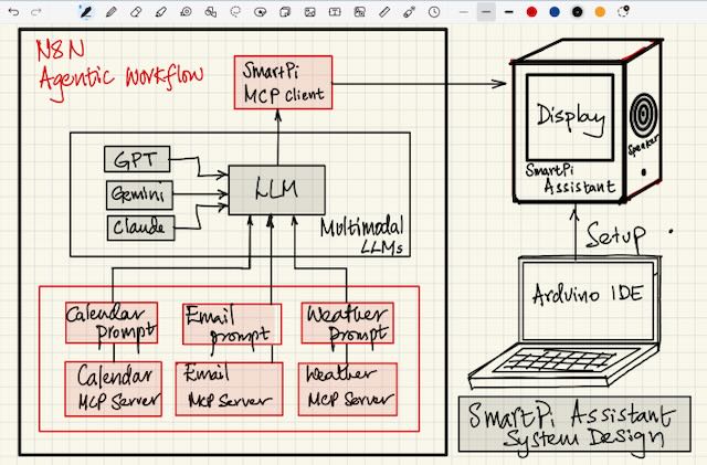
n8n Workflow Architecture
To orchestrate the data collection and LLM processing, I built an n8n workflow that automates the entire pipeline from data sources to SmartPi display output. The workflow is triggered manually or on a schedule and consists of three parallel processing branches:
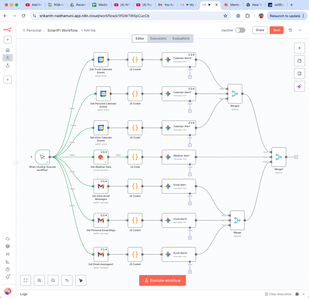
The workflow architecture consists of the following components:
- Create an Assistant Node: Initializes an AI assistant instance at the start of the workflow, configuring the LLM that will process and summarize the incoming data.
- Manual Trigger: The "When clicking 'Execute workflow'" node allows on-demand execution for testing and immediate updates.
- Calendar Branch:
- Get Calendar events: Fetches upcoming events from Google Calendar API
- JS Code1: Processes and filters calendar data, extracting relevant meeting information
- Calendar Alert: Sends formatted calendar notifications to the SmartPi display via MCP
- Weather Branch:
- Get Weather Data: Retrieves current weather conditions from OpenWeatherMap API for Cambridge, MA
- JS Code: Formats weather data and generates contextual advice (e.g., "Wear a Jacket" if temperature is below 40°F)
- Weather Alert: Displays weather summary and recommendations on the SmartPi LED matrix
- Email Branch:
- Get Email messages: Connects to email via IMAP and retrieves recent unread messages
- JS Code2: Extracts sender and subject information, passing it to the LLM for summarization
- Email Alert: Sends concise email summaries to the SmartPi display
All three branches execute in parallel, allowing the workflow to aggregate multiple data sources simultaneously. Each branch processes its data independently and sends MCP commands to the SmartPi bridge server, which then forwards display instructions to the Raspberry Pi Pico W. This parallel architecture ensures low latency and enables the SmartPi Assistant to provide real-time, multi-source contextual alerts.
The workflow demonstrates the power of visual programming for agentic systems — complex data orchestration, LLM integration, and hardware control are all coordinated through a no-code interface, making the system easy to modify and extend as new data sources or output modes are added.
Software Design and MCP Integration
For the software integration of the SmartPi Agentic Assistant, I decided to implement a Model Context Protocol (MCP)–based architecture to connect my n8n agentic workflow with the SmartPi hardware. MCP provides a standardized way for different AI agents, tools, and hardware components to communicate through a shared schema of "tools" and "contexts." This approach gives my project modularity, expandability, and long-term flexibility as I add new capabilities.
Using MCP to connect n8n and the SmartPi
In my setup, the n8n workflow — which collects inputs from email, calendar, and weather APIs and processes them through an LLM — acts as the MCP client. The SmartPi device, through a lightweight bridge service I wrote in Python, acts as the MCP server.
The MCP client (n8n) sends structured messages to the server whenever the workflow produces an actionable summary. For example, when my LLM determines that I have an upcoming meeting, the workflow constructs an MCP message like:
{
  "tool": "display_text",
  "args": {
    "text": "Meeting at 10:30 AM with John Doe",
    "fg": "#00FF00",
    "bg": "#000000"
  }
}
This message is passed to the SmartPi MCP server, which exposes functions such as display_text(), fill_color(), and show_icon(). The server then forwards these commands to the Raspberry Pi Pico W via Wi-Fi or serial communication, using a simple JSON-based protocol.
Role of MCP client and server in my design
In this system:
- The MCP client (n8n workflow) is responsible for interpreting data sources (email, calendar, weather) through an LLM, identifying key insights, and sending display commands to the hardware.
- The MCP server (SmartPi bridge service) runs on a small Python runtime on the network. It listens for MCP messages from n8n and translates them into low-level commands that the Pico W can execute.
- The Raspberry Pi Pico W acts as the hardware endpoint, receiving commands over Wi-Fi, and rendering them on the 64×64 LED matrix using CircuitPython's displayio and rgbmatrix libraries.
Conceptually, the workflow looks like this:
flowchart TD
    subgraph n8n["n8n Agentic Workflow"]
        Node["LLM Node"]
    end

    subgraph BridgeServer["SmartPi MCP Bridge Server"]
        PythonAPI["Python + FastAPI + mcp-tools"]
        ExposedAPIs["Exposes MCP functions:
'display_text', 'fill_color', etc."]
    end

    subgraph Pico["Raspberry Pi Pico W"]
        CircuitPython["CircuitPython Firmware"]
        LEDMatrix["64×64 LED Matrix Display"]
    end

    Node -->|"MCP Client sends JSON"| BridgeServer
    BridgeServer -->|"Wi-Fi JSON command"| Pico
    Pico -->|"Parse JSON → Update LEDs"| LEDMatrix
Why I chose MCP
I chose to integrate MCP because it provides a modular and extensible interface for hardware-agent communication. Instead of hard-coding MQTT topics or HTTP endpoints, the SmartPi's capabilities can be exposed as well-defined "tools". This allows me to easily add new hardware features later — such as microphone input, temperature sensors, or speech output — by simply registering new MCP tools on the server side.
This architecture also aligns well with the agentic computing theme of my project: the SmartPi becomes a peripheral that LLMs and automation workflows can interact with contextually, rather than a passive display device.
How this fits into my workflow
The n8n workflow aggregates and summarizes my daily digital inputs — for example:
- "Weather: 27°F in Cambridge, MA — Wear a Jacket"
- "Meeting at 10:30AM with John Doe"
- "New email from project team: Summary attached."
When these events are generated, the MCP client in n8n sends them directly to the SmartPi MCP server, which immediately updates the LED matrix display through the Pico W. This push model ensures that the device reflects real-time, meaningful summaries without requiring the Pico to constantly poll for updates.
Future directions
By structuring my software around MCP, I can later connect the SmartPi system to other MCP-compatible environments — for example, ChatGPT or LangChain-based local agents — allowing LLMs to control the physical device directly. This makes the SmartPi Assistant not just a display, but a node in a larger context-aware ambient intelligence network.
Appendix: Implementation Details — MCP Bridge Server
To implement the MCP bridge between my n8n workflow and the SmartPi device, I created a lightweight Python MCP Server that runs on my laptop (or on a Raspberry Pi Zero). This server exposes a set of "tools" compliant with the Model Context Protocol, so that any MCP client — such as my n8n agentic workflow — can invoke them to control the SmartPi hardware.
MCP Bridge Architecture
The bridge acts as the translation layer between high-level agentic intents (like "display meeting reminder") and low-level hardware commands (like "fill the screen blue and render text"). It communicates with the Raspberry Pi Pico W over Wi-Fi via a simple HTTP or WebSocket interface.
The software stack is structured as follows:
[n8n Agentic Workflow / LLM Node]
        ↓
 (MCP Client sends JSON)
        ↓
[SmartPi MCP Bridge Server]
  - Python + FastAPI + mcp-tools
  - Exposes "display_text", "fill_color", etc.
        ↓
 (Wi-Fi JSON command)
        ↓
[Raspberry Pi Pico W running CircuitPython]
  - Parses JSON, updates 64×64 LED Matrix
MCP Server Implementation (Python)
Below is the simplified version of my MCP bridge code. It defines a small set of SmartPi tools (display_text, fill_color) and handles incoming MCP calls from the n8n workflow.
# smartpi_mcp_server.py
from fastapi import FastAPI
from pydantic import BaseModel
import requests
import os

app = FastAPI(title="SmartPi MCP Bridge")

# Device configuration
SMARTPI_DEVICE_URL = os.getenv("SMARTPI_DEVICE_URL", "http://192.168.1.100:8000/update")

# Define MCP-compatible request schema
class MCPCommand(BaseModel):
    tool: str
    args: dict

@app.post("/mcp")
def handle_mcp(cmd: MCPCommand):
    """Receive tool calls from an MCP client (e.g. n8n)."""
    tool = cmd.tool
    args = cmd.args

    if tool == "display_text":
        payload = {
            "mode": "text",
            "text": args.get("text", ""),
            "fg": args.get("fg", "#FFFFFF"),
            "bg": args.get("bg", "#000000")
        }
    elif tool == "fill_color":
        payload = {"mode": "fill", "color": args.get("color", "#000000")}
    else:
        return {"error": f"Unknown tool '{tool}'"}

    try:
        r = requests.post(SMARTPI_DEVICE_URL, json=payload, timeout=3)
        return {"status": "ok", "device_response": r.json()}
    except Exception as e:
        return {"status": "failed", "error": str(e)}

# Optional: expose metadata for MCP discovery
@app.get("/.well-known/mcp.json")
def mcp_manifest():
    return {
        "name": "SmartPi MCP Server",
        "description": "Bridge for controlling SmartPi LED matrix and peripherals",
        "tools": [
            {
                "name": "display_text",
                "description": "Render text message on SmartPi LED matrix",
                "parameters": {
                    "text": "string",
                    "fg": "string (hex color)",
                    "bg": "string (hex color)"
                }
            },
            {
                "name": "fill_color",
                "description": "Fill the SmartPi screen with a single color",
                "parameters": {"color": "string (hex color)"}
            }
        ]
    }
I run this service using:
uvicorn smartpi_mcp_server:app --host 0.0.0.0 --port 5055Once running, any MCP-compatible client (including n8n, LangChain, or ChatGPT with MCP) can call:
POST http://<bridge-ip>:5055/mcp
{
  "tool": "display_text",
  "args": {"text": "Meeting at 10:30AM", "fg": "#00FF00", "bg": "#000000"}
}
The server immediately forwards this to the SmartPi device via Wi-Fi, which then updates the LED matrix accordingly.
Pico Listener Firmware
On the Raspberry Pi Pico W, I modified my earlier CircuitPython program to act as a lightweight listener. It exposes a simple HTTP endpoint (/update) to receive JSON payloads. This keeps the device code minimal and makes it protocol-agnostic — the Pico doesn't need to know anything about MCP, only how to parse commands.
# code.py on Pico W
import wifi, socketpool, adafruit_requests, board, displayio, framebufferio, rgbmatrix, json
from secrets import secrets
from adafruit_display_text import label
import terminalio

# Wi-Fi setup
wifi.radio.connect(secrets["ssid"], secrets["password"])
pool = socketpool.SocketPool(wifi.radio)
requests = adafruit_requests.Session(pool, None)

# LED Matrix setup (same as before)
displayio.release_displays()
rgb_pins = [board.GP2, board.GP3, board.GP4, board.GP5, board.GP8, board.GP9]
addr_pins = [board.GP10, board.GP16, board.GP18, board.GP20, board.GP22]
clock_pin, latch_pin, oe_pin = board.GP11, board.GP12, board.GP13

matrix = rgbmatrix.RGBMatrix(
    width=64, height=64, bit_depth=5,
    rgb_pins=rgb_pins, addr_pins=addr_pins,
    clock_pin=clock_pin, latch_pin=latch_pin,
    output_enable_pin=oe_pin
)
display = framebufferio.FramebufferDisplay(matrix)

palette = displayio.Palette(1)
bitmap = displayio.Bitmap(64, 64, 1)
tile = displayio.TileGrid(bitmap, pixel_shader=palette)
group = displayio.Group()
group.append(tile)
display.root_group = group

label_area = label.Label(terminalio.FONT, text="", color=0xFFFFFF)
group.append(label_area)

def fill(rgb_hex):
    palette[0] = rgb_hex

def show_text(msg, fg, bg):
    fill(bg)
    label_area.text = msg
    label_area.color = fg

# Minimal web server to receive updates
import adafruit_httpserver
server = adafruit_httpserver.Server(pool, "/update")

@server.route("/update", methods=["POST"])
def handle_update(request):
    data = request.json()
    mode = data.get("mode")
    if mode == "fill":
        fill(int(data.get("color").replace("#", "0x"), 16))
    elif mode == "text":
        fg = int(data.get("fg").replace("#", "0x"), 16)
        bg = int(data.get("bg").replace("#", "0x"), 16)
        show_text(data.get("text", ""), fg, bg)
    return request.respond("OK")

print("SmartPi listening at:", wifi.radio.ipv4_address)
server.serve_forever()
How it all comes together
When the n8n workflow produces an actionable event:
- The MCP client node sends a
display_textcommand to the MCP server. - The SmartPi MCP Server translates this into a
/updaterequest to the Pico W. - The Pico W updates the LED display instantly.
This architecture cleanly separates responsibilities:
- n8n (logic + reasoning)
- MCP bridge (protocol + translation)
- Pico W (hardware control)
By building the integration around MCP, I've made the SmartPi Assistant a general-purpose agent endpoint — it can now accept commands not only from n8n, but also from any other MCP-compliant tool, LLM agent, or automation framework.