

- Walks on four legs
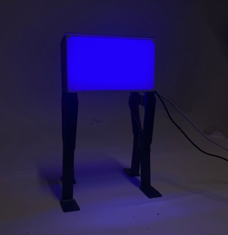
- Changes colors
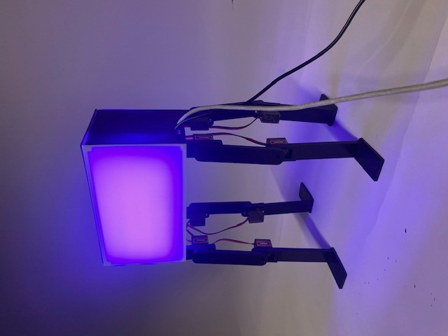
- Turns purple with polka dots when tapped
- Clean and intentional design - I want it to look nice!
I found a lot of tutorials for making quadruped robots. The ones I used most prevalently to understand the scope of my project are: Arduino Powered Micro Quadruped Tutorial and Simple Quadruped Robot on Hackster.
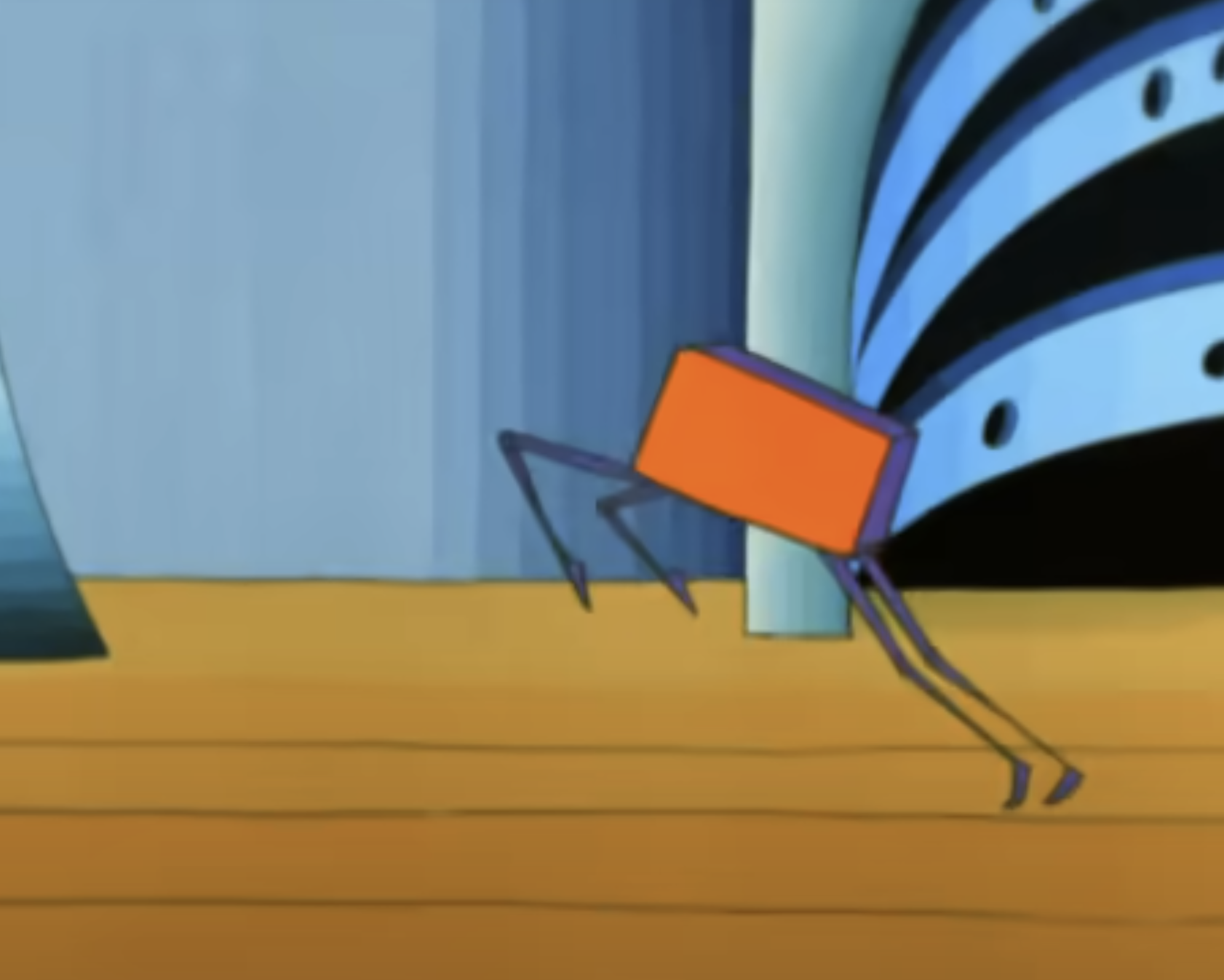
For the specific indicator character, I found one person who had made an indicator lamp before. This version only lights up and does not walk: Indicator Lamp Video.
For electronics production week, I made the first version of my pcb, on which I tested servos and using the wallwart for power. For input devices week, I made a protoype for the touch sensor. For output devices week, I created the first version of CAD for legs and tested the motion of one leg with two motors.
.png)
After the completion of machine week, I focused my time on my final project.
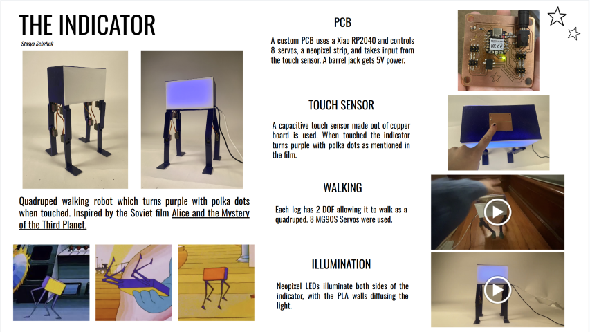
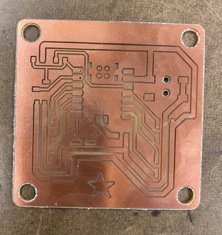
I started off by designing and machining my PCB. This PCB uses a Xiao RP2040 to control 8 servos, 1 NeoPixel strip, and has a touch sensor. It uses a barrel jack plug that gets connected to a wall wart to power the servos and NeoPixel, as a computer through the Xiao cannot provide enough current. Also, it’s important to note that the pins for the LED strip are not in the same order as they are on the LED strip. This is because having them in the right order led to the traces being really small and close to each other. To have fewer failure modes, I decided I would just use jumper cables to switch the wire order.
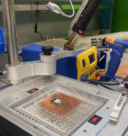
I asked Anthony for help with soldering as I needed to access a pin on the back of the Xiao. He helped SMD solder the Vin pin. I soldered the rest of the components with a soldering iron.
Walking
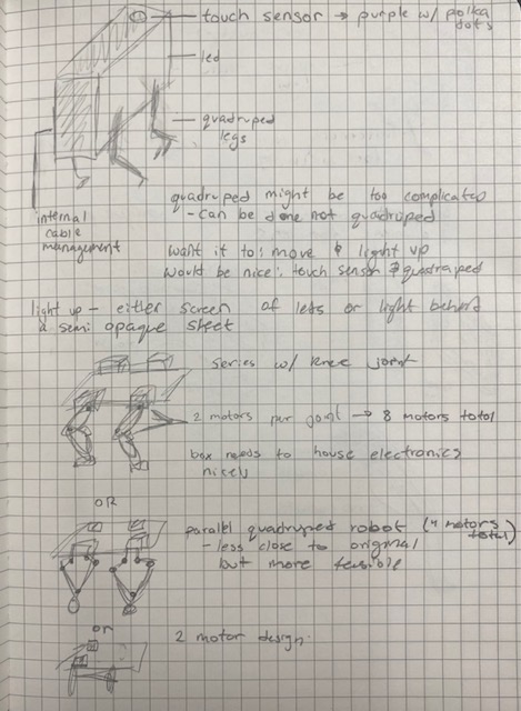
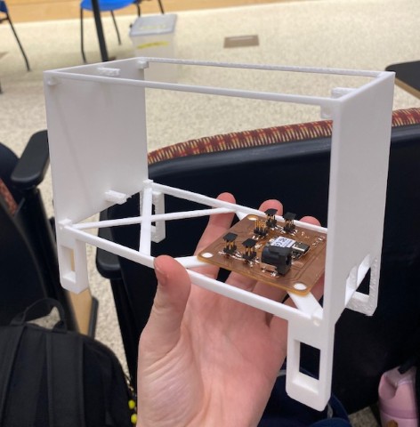
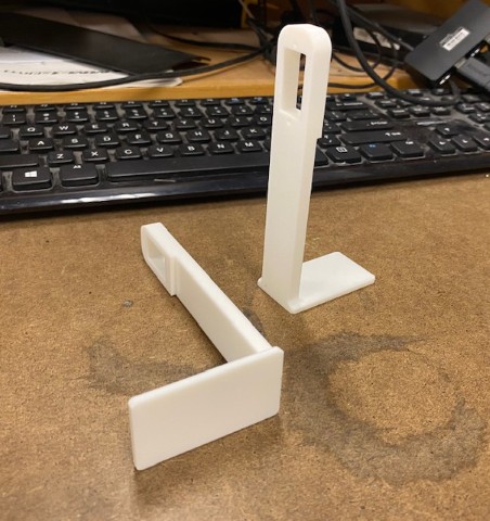
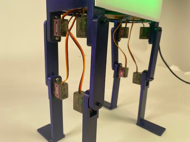
In parallel to making the PCB board, I worked on the CAD of the indicator. I CADed legs that were shorter than the legs I had previously tested with. The legs consist of two links and are controlled by a servo motor at each joint. I also adjusted the spacing of the holes so the servos would properly mount. I also CADed the body so I could test the leg and PCB mounting to the body.
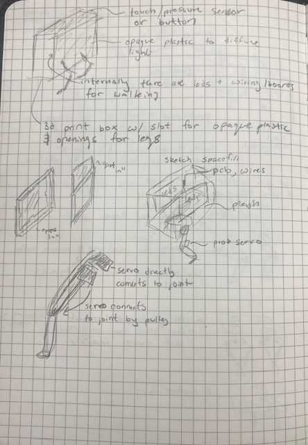
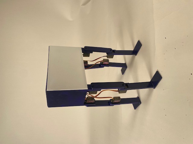
I 3D-printed one leg and the bottom of the body. When seeing them printed, I realized I wanted to make the body smaller. When assembling with the servo motors, I decided that I wanted to add a bolt that bolts into the horn of the servo and securely attaches the servo to the 3D print. I found some 14 mm M2.5 bolts and CADed legs that have holes for the bolt. I made these adjustments and 3D-printed the full body and a full set of legs.
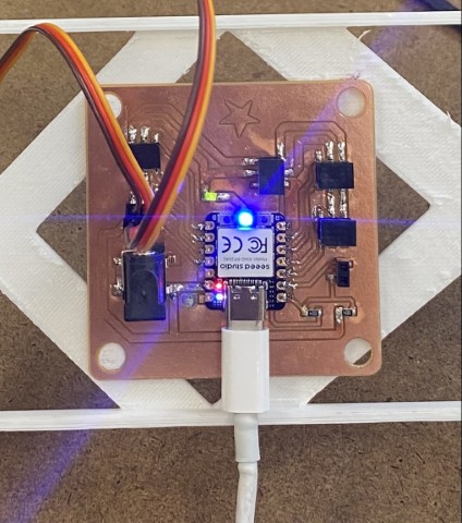
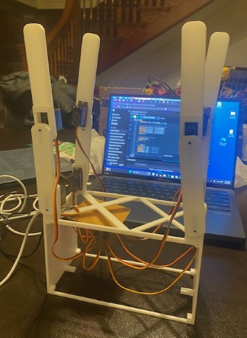
I ran a test with the PCB controlling the servos connected in the leg configuration, which was a success. My next test was connecting the PCB to 8 servos and ensuring that it could control all of them at the same time, which it could. Once I got all 8 servos, I was able to assemble all the legs and have the indicator stand up as proof the robot could hold up its own weight. I also placed a heavy power brick inside the box and it did not break.
I had ChatGPT write code that sets all the servos to 90 degrees and then I assembled the legs to be straight in this configuration. Then I asked it to write code to make the robot walk. It wasn’t able to walk on the smooth table, and I thought it might be a friction issue so I moved the robot to the carpet. The robot was able to take a couple steps before toppling over. I found some balloons and covered the feet in them to provide more grip.
I experimented with different leg positions and different angles of walking; however, I was unsuccessful in getting a working walking code, as the robot kept falling over. I decided to 3D-print some legs that have a wider base. I didn’t do this originally as I wanted my design to match the form factor of the indicator as closely as possible. I also asked Anthony for some advice, and he suggested a couple of ideas, with one of them being giving the legs a wider base.
I 3D-printed the legs with a wider base, which made the robot more stable and its walking more promising.
I was unable to get the “lift one leg at a time” method of walking to work, so instead I changed the walking to a shuffle pattern that had better success. The robot performs better on certain surfaces than others. I am able to get a walk forward out of it. If I had more time, I would spend more time tuning the code to have it walk more consistently.
Touch Sensor
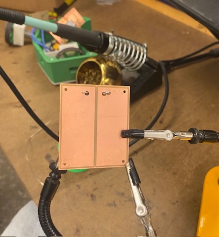
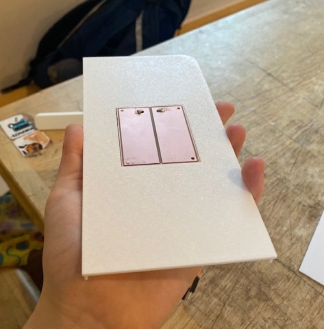
I designed a “PCB” for the touch sensor, which is simply two copper pads as the touch sensor is not at the location of the PCB. There are holes in the pad to mount to the indicator and also holes to connect wires that will connect the touch sensor to the PCB. I milled out the touch sensor on the mill.
I initially soldered a connector to connect to traces for the touch sensor. However, at some point the connector came loose and ripped the traces. So instead, I soldered two pins into the holes on the Xiao and used a male-to-male jumper cable. On the touch sensor itself, I soldered two pins to connect to each of the copper pads. I 3D-printed the top of the box, which has a housing for the touch sensor.
Lights
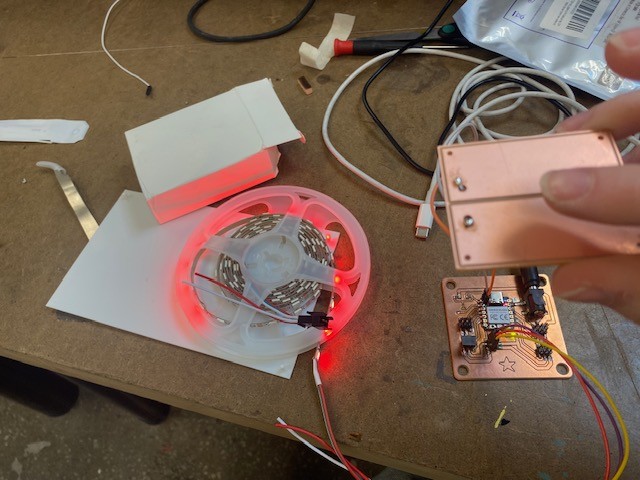
For the lights, I ordered a NeoPixel Strip online. I had ChatGPT write simple code to control it, and I used jumper wires to connect it to my PCB and tested that my PCB could control the lights.
Then, I worked on integrating the touch sensor and lights by getting code (from ChatGPT) that has the lights slowly change colors, but turn purple when the sensor is touched. I used the serial monitor in Arduino to adjust the sensitivity of the touch sensor. I then made it so every fourth LED turns green to mimic polka dots. When I have the LEDs attached in the final assembly, I will adjust which LEDs I want to be non-purple.
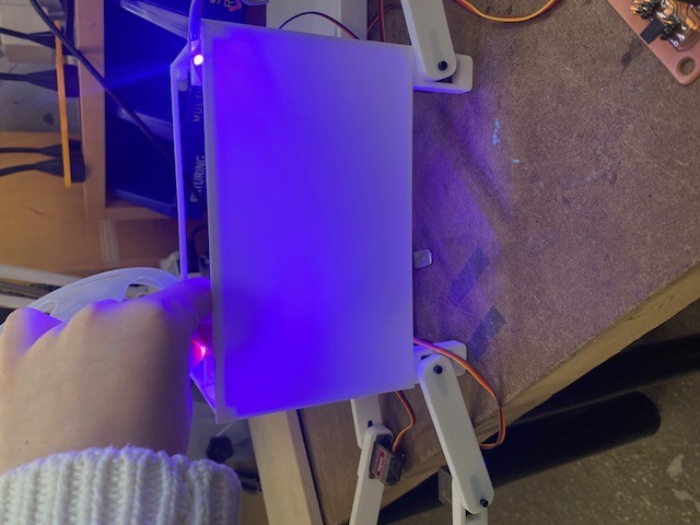
Next, I printed the two walls of the indicator. These walls are 1 mm thick and diffuse the light from the LEDs. They have pegs so they snap into the side of the box.
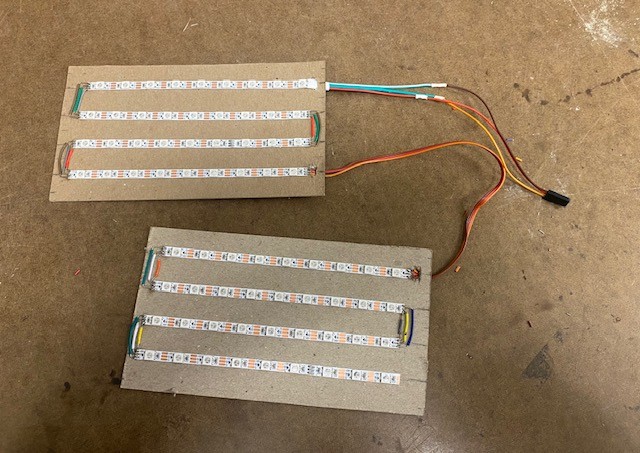
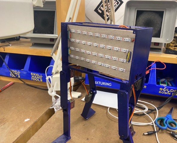
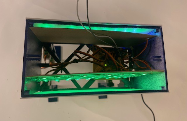
I realized that with a central placement for the LEDs, you could see the outline of the internal wiring when the lights are on. I didn’t want to reprint the box unless it was absolutely necessary, as it is a 9-hour print. I realized that I could use cardstock inserts on two sides and stick the lights to the sides that face the diffuser, then route all the wiring in between the inserts.
I used the laser cutter to cut out test pieces, mounted the NeoPixel strips, soldered connectors, and wired the strips in series while ensuring correct data direction. I used a multimeter throughout the process to confirm power and ground continuity and avoid shorts. I ended up having to cut down the pieces of cardstock as I laser cut them to the wrong size. Ideally, I would've laser cut them to the correct size, laser cut holes for the LEDs and even engraved lines to guide LED placement. Alas time management got the best of me!
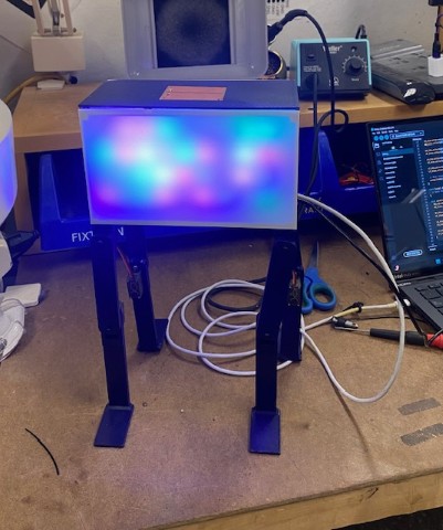
I inserted the finished light assemblies into the indicator and tested them with the walls attached. The lights worked successfully.
Final Assembly
After having enough confidence in each of the components working, I spray-painted the base, top, and legs purple. I continued working before the paint was fully dry, so there are minor specks in the finish, though they are not noticeable unless pointed out.
I attached the PCB to the body, connected all the servos, assembled the legs, cleaned up the wiring with zip ties, installed the light assembly, connected the touch sensor, snapped on the walls, and attached the lid. Unfortunately, in testing all the pins to secure the top snapped off, so if I were to remake this design I would increase their diameter.
Code Integration
After having the light code and walking code working separately, I tried to have them work together. This is where I ran into an issue: when everything ran together, all but one servo worked. Running the code separately worked fine. After discussing with Anthony, he suggested it might be a timer issue. Due to limited coding knowledge and available pins, this issue was not resolved. I decided to use two main code files: one for walking and one for light control.
Evaluation and Implications
I evaluate my project based on the four goals I set for myself in my ideation phase which were: - walks on four legs, changes colors, turns purple with polka dots when tapped, clean and intentional design. I would say that I hit the MVP (minimal viable product) on each of these four goals, but there is still room for improvement. The main improvement is getting it to light up and walk at the same time. In terms of intentional design, there are a bunch of little things that can be improved to make the design better. Due to the time constraints of this class and not being able to justify reprints over small errors these small things have remained unfixed. I learned a lot in this class and quite enjoyed the process. Personally, an implication that comes from this is the skills I’ve gained and developed in design and digital fabrication. In research terms, I’ve taken the literature a step further by going from an indicator that only lights up to one that also walks.
BOM
| Part | Number | Where Did It Come From | Cost ($) | Notes |
|---|---|---|---|---|
| Leg Link 1 | x4 | 3D Printed / Arch Shop | 1.00 | |
| Leg Link 2 | x4 | 3D Printed / Arch Shop | 1.00 | |
| Body | x1 | 3D Printed / Arch Shop | 1.00 | |
| Wall | x2 | 3D Printed / Arch Shop | 0.20 | |
| Top | x1 | 3D Printed / Arch Shop | 0.20 | |
| MG90S 9g Micro Servo Motor | x8 | Class Inventory | 20.00 | |
| M2.5 x 14 Socket Cap Screw | x8 | EECS Shop | 0.80 | |
| M3 Screw | x16 | Class Inventory / w/ Servo | - | |
| Copper PCB Board | x2 | Class Inventory | 2.00 | |
| 3x2 Pin Header | x5 | Class Inventory | 0.75 | |
| 1206 LED | x1 | Class Inventory | 0.15 | |
| Seeed Xiao RP2040 | x1 | Class Inventory | 3.50 | |
| Barrel Jack Header | x1 | Class Inventory | 0.57 | |
| 2 Pin Header | x1 | Class Inventory | 0.10 | |
| Female-to-Female Jumper Cable | x2 | Class Inventory | 0.20 | |
| 1 Pin Header | x2 | Class Inventory | 0.10 | |
| Loose Wire | - | Class Inventory | 2.00 | |
| NeoPixel LED Strip | x1 | Amazon | 8.99 | Not covered by class |
| 1/16 Inch Cardstock | x2 | Arch Shop Reuse | 1.00 | |
| Spray Paint | x1 | Blick | 7.99 | Not covered by class |
| Barrel Jack Wall Wart | x1 | Anthony | 10.00 | |
| Total Cost | 61.55 | |||
Files
Walk code