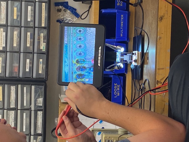
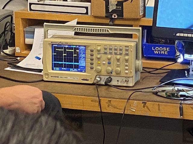
Gert showed some other students and me how to use the oscilloscope and multimeter. We tested the functionality of the microcontroller he used for his HTMAA final project. Using the oscilloscope, we measured the voltage at the clock port and the data port, where we observed a difference in voltage. From the voltage signal, we could see that the data port was transmitting a series of binary outputs. With the multimeter, we used the resistance mode to check whether different components were connected.
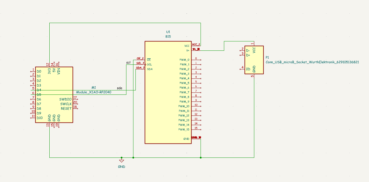
For designing my PCB, I used Kicad. I started by installing Kicad, the fab lab inventory, and setting the design rules based on Quentin’s tutorial. I decided to design the PCB board I would use for my final project. For this I need to interface with 8 servo motors and with an LED strip. I found the ”Adafruit 16-Channel 12-bit PWM/Servo Driver - I2C interface - PCA9685 “ to use to control the servos as it generates the PWM signal in hardware making it more stable and it has the ability to have 6 PWM outputs in case I later decide I need for pwm outputs. Additionally, this board allows me to have a separate 5V supply which is needed as the servos can possibly draw a lot of current that I do not want going through the microcontroller. I decided to use the Seeed XIAO RP2040 as it was suggested that this was the easiest one to use for a beginner.
In Kicad I had to import the PCA9685 as the ones in the library did not have the correct footprint. I found this symbol and footprint and uploaded it to my library. Then I drew the schematic in Kicad connecting all the wires. For the first version of my PCB I only included the servo motors and did not add the LED lights for my final project as I haven’t chosen what lights I am using. One helpful tip was to check which grounds on the XIAO were easy to access and to use that one as my ground to make the soldering easier.
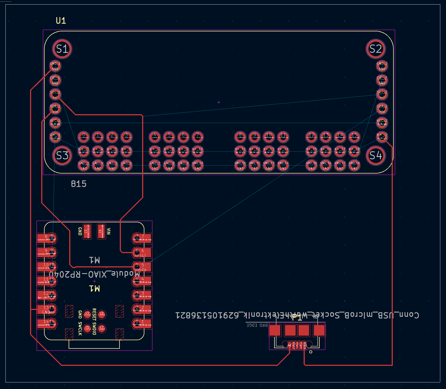
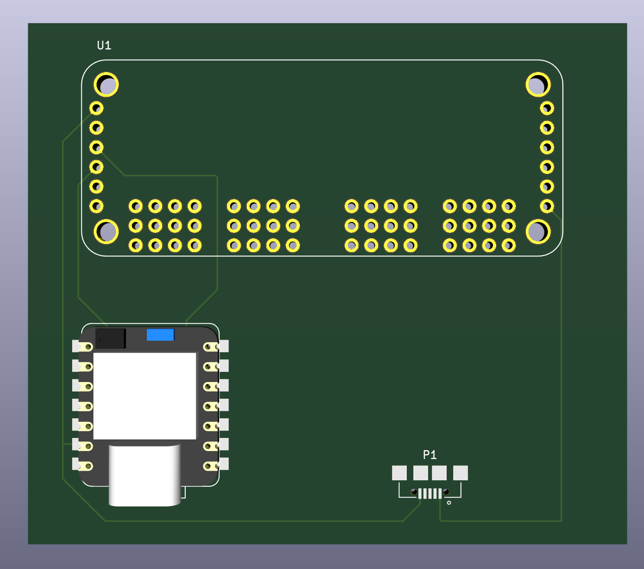
I ran into an issue in the pcb editor because somehow my ratsnest was not visible in my editor. Alfonso and Alan were both surprised as this was an issue they’ve never seen before. After Alan did some intense debugging, we found out that in the objects tab the ratsnest was set to invisible. So the bug was actually a simple misclick. After that I was off creating the paths in the PCB editor which was pretty simple and fun to do. Alfonso looked over my design and suggested that I move my paths farther apart from all the pins in my design as if they misaligned then my pcb would short.
After completing this whole assignment, I talked to Anthony who told me it was reasonable for me to run all the servos directly on the Xiao without the breakout board, so for next weeks assignment I will be redesigning my pcb. Still, this board provided a good introduction to pcb design and this practice will make it easier for when I make my own board next week.