.png)
.png)
.png)
Architecture Section Group Assignment.
- submit a PCB design to a board houseI worked with Adin and Ayah to send out an earlier version of my board to JLCPCB. Photos to come.
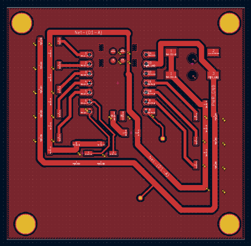
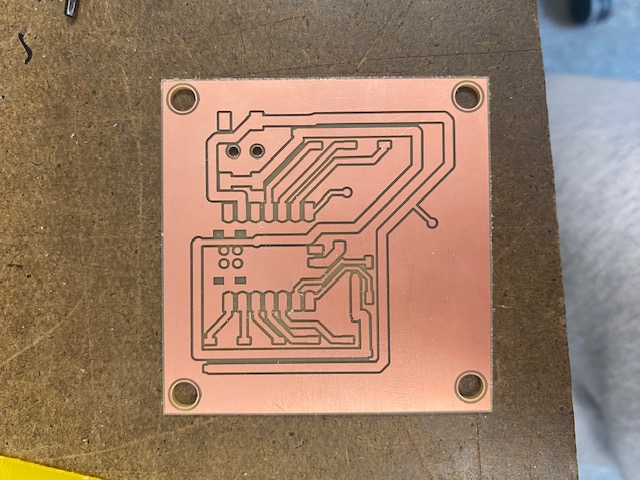
For my microcontroller board, I designed a board that I could use for my final project. In its current state, my final project needs 8 servos, 1 neopixel strip, and a button. I’m using a separate barreljack wall wart power supply to power the servos and neopixels. I also decided to add an extra neopixel slot, because I’m unsure if I need one or two. There isn’t a button on the board as I want it to be on the outside of my robot, so I created holes where I can insert jumper wires that would go to a button. I designed my board in Kicad. Anthony was a tremendous help in checking my board and giving me advice. A key takeaway was to make my 5V and ground tracks bigger as a lot of power will go through them when I have all 8 servos connected. Gert suggested that I add mounting holes to my board, as in my final project I would want to mount the pcb to something.
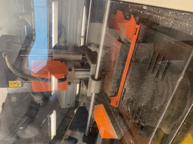
Gert helped me mill the board on the Modela and it milled everything except it didn’t recognize to mill some of the smaller holes. Later, I saw another student’s board which had holes of similar size milled, so I will troubleshoot more for my final board. To mill the board, I used Quentin’s website which turned the gerber files of my pcb board into pngs and then uploaded these pngs to the architecture shops program to mill the board.
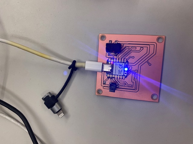
When assembling the board, the first issue I ran into was that I flipped the orientation of the barrel jack so it was going in the opposite direction of what I intended. Due to this, the board will have to be remade for my final project, as I won’t be able to attach all the headers I need for the servos. For the purpose of this assignment, I soldered on the barrel jack, a Xiao Seeed RP2040, and one header for a servo.
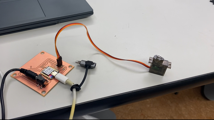
I ran into trouble with actually getting my board to work. I was able to control the Xiao LEDs, but not the servo. I used my multimeter debugging skills to check that all the traces were properly connected and that the servo was actually getting 5 volts. Anthony came to save the day when he tested if the actual headers were connected to the traces and found that I didn’t solder the ground pin on properly. I quickly fixed the solder and my chat gpt code controlled my servo. Success!! My board will have to be remade for my final project, but this was a great learning experience.