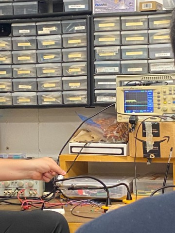
For the group assignment, Gert showed us the power consumption of a stepper motor, by showing us its performance at different voltage inputs. He then showed us how a LED fails by increasing the voltage till it blows up.
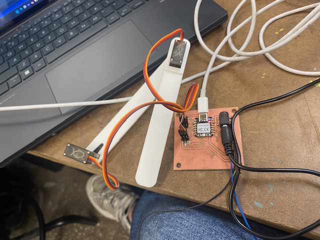
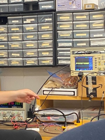
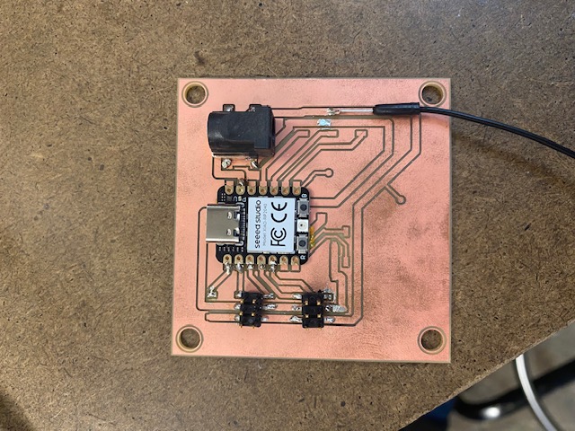
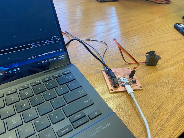
For this assignment, I decided to continue working on my final project PCB board. For electronics design week, I had made a PCB board for servos and tested it with one servo motor. For this week, I decided to test it with a second servo motor and an assembly closer to my final project. I started by soldering on an additional connector, so I can attach a second servo motor. Then I tested the board with two servo motors plugged in. Unfortunately, I ran into issues because the motors were stalling and not behaving the way the code was indicating. Gert suggested that this was due to them not getting enough power from the barrel jack, so we soldered on wires and connected the ground and 5V directly to a variable power supply. When this did not solve the issue, he suggested going to Anthony for help. Anthony looked at my board and suggested the connection to the ground on the Xiao wasn’t good and I should resolder it. On inspection, my Xiao is slanted as there is excess solder under the ground which is probably the reason for this bad connection. I added more solder to the ground on the Xiao and the issue with the motors stopped. The code that was used was written by ChatGPT and moved the position of the servo motor to a specified value. Anthony suggested changing the pulse width value to 500 - 2500 from the default pulse width to get the servos to move at their full range of motion.
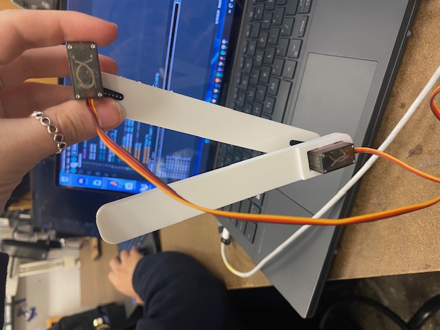
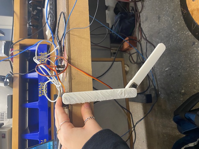
To have this project help progress with my final project more, I decided to CAD and 3D print a possible leg design and test the motors in the leg configuration. The servos were able to move the legs.