3D Topographical Map of Jamaica
3D Scanning and Printing Project
Requirements
Design, document and 3D print a topographical map of Jamaica in a manner that could not be made subtractively.
Manipulate the design rules of a 3D printer for artistic purposes.
Incorporate 3D scanned object in design.
Design
It's been over a year since I've been home or seen my family and friends in Jamaica.
I wanted to create something that would serve as a reminder while I'm away.
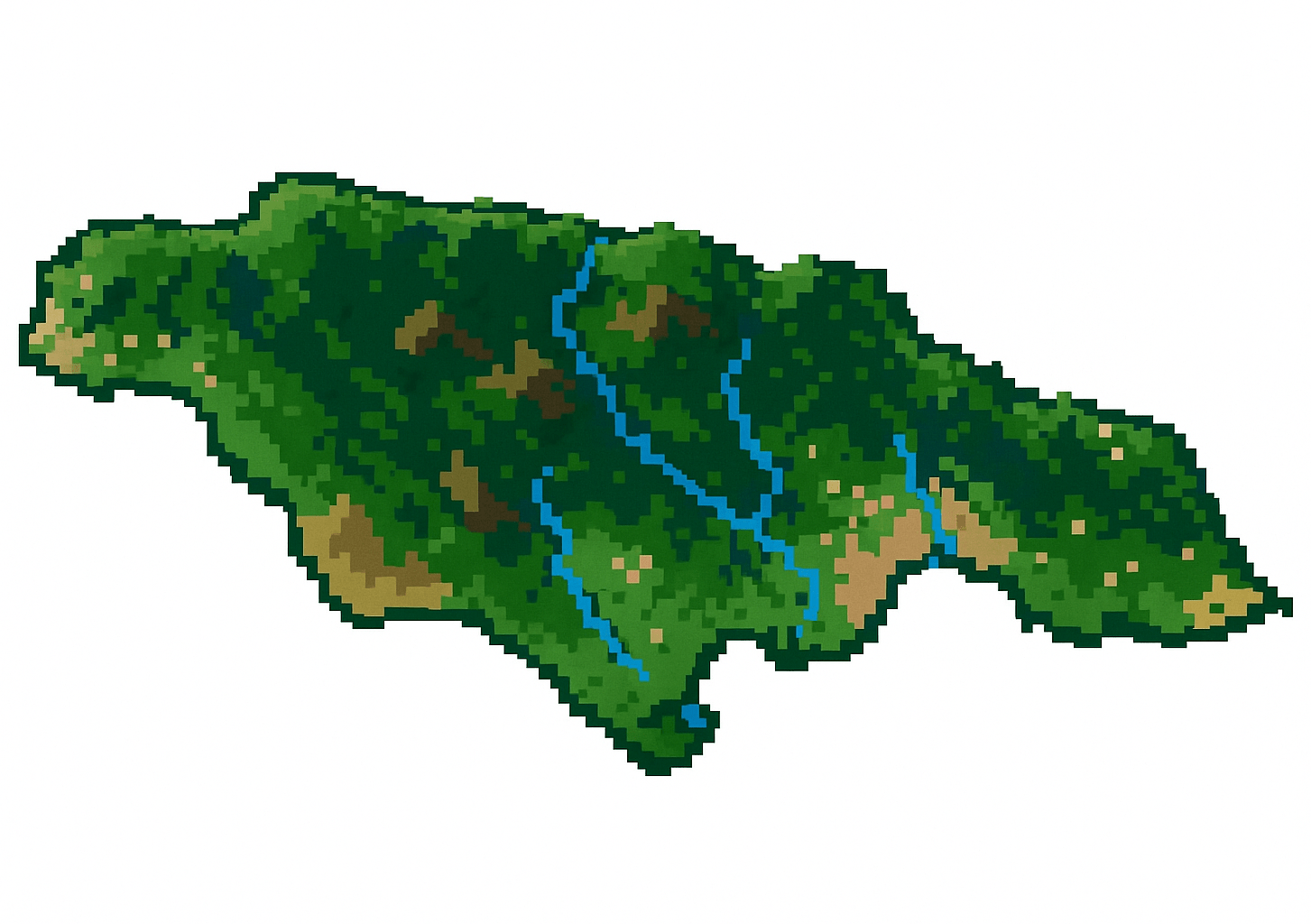
I decided on a 3D topographical map of Jamaica, adding simplified rivers and buildings to make it more playful.
I also attempted to exploit the design features of 3D printers, using tree supports to make trees, gyroid infill to suggest waves, and translucent filament with low infill for glistening waters.
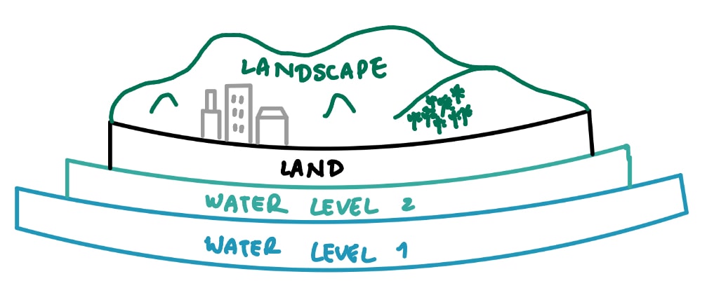
Before modelling, I sketched out how I wanted the CAD to be structured.
Modelling
I wanted the model to include multiple colors, but instead of relying on the Bambu Lab for multicolor printing, I decided to split the model into separate press-fit parts.
I chose this because the printer swaps colours by purging filament between changes, which wastes material and adds a lot of extra print time.
This resulted in a faster print with greater flexibility in choosing colors and materials.
1. Processing Terrain Data
I started by downlading a digital elevation model of Jamaica from Opentopography.
I then imported the tagged image file to QGIS, where I adjusted the horizontal scale so that the width of the model would be ~150mm.
To make the terrain more noticeable at that small scale, I exaggerated the elevations so that hills and valleys would be more visible in the print.
Next, I exported the model to an stl file so that I could open and edit it in SolidWorks.
At this point, I didn't really understand the difference between meshes and boundary representations (BREPs), so I assumed the workflow would be business as usual.
As soon as I inserted the stl file in SolidWorks, my computer's fan started blasting as loud as a jet engine before takeoff, the program froze and then my laptop crashed.
Initially, I thought it was just my laptop because it also has mini strokes whenever I had to use Altium Designer for MIT Motorsports, so I ready to ...
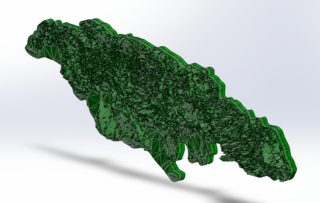
But after a little research, I learned that the file I had imported had about 1.5 million faces, which is way more that SolidWorks is able to handle. I brought the file into MeshLab and used the Quadratic Edge Collapse Decimation filter twice to reduce the number of faces to 40,000. With that light mesh imported, I could finally make edits. I learned to use Projected Curve and Split Line to wrap sketch geometry (like rivers) onto the terrain, and then used Indent Cut to carve channels into the landscape. These are tools I had never used before, but they made the process a lot more efficient.
This is what the CAD for the terrain looked like in the end.
2. Water Layer 1
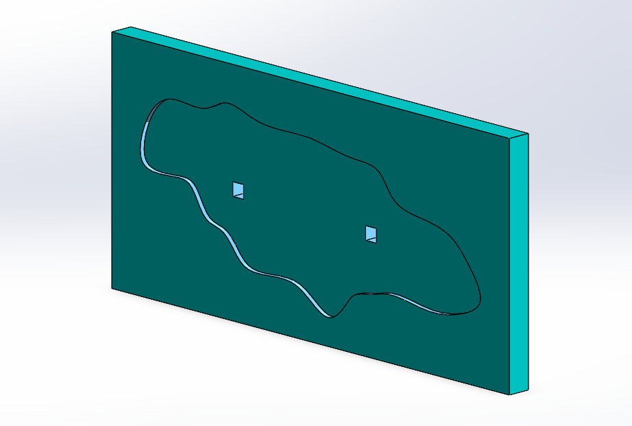
For the first water layer, I began by sketching a spline around the outline of the island to capture the general shape. I then drew a large rectangle around this spline so I would have both an inner and outer boundary to work with. Using Extruded Boss/Base, I extruded the different surfaces to slightly different depths so that the second layer could eventually nestle in more securely. I also added a set of rectangular holes in this layer, which would later be paired with rectangular pins on Water Layer 2. These alignment features ensured that the two layers would lock together precisely instead of just stacking loosely.
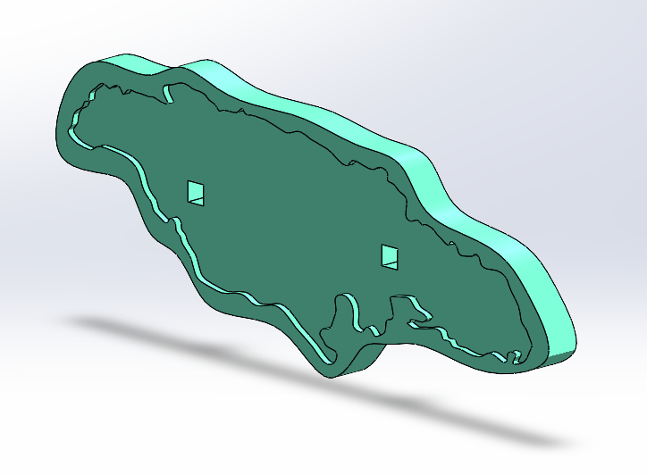
3. Water Layer 2
For the second water layer, I started by using the Intersection Curve tool to capture the exact outline of the terrain model, which defined the inner boundary where the island would sit. I combined that with the larger outline from Water Layer 1 to define the outer edge. Between those two boundaries, I created an Extruded Boss/Base so the layer formed a ring that fit snugly around the island and pressed neatly into the first water layer. To align the two layers securely, I added rectangular pins in this layer that matched the rectangular holes I had cut into Water Layer 1. I also added additional holes so that the pins from the terrain model itself could press-fit into the second water layer.
4. Additional Features
Buildings
I kept it simple by sketching rectangles in the appropriate areas and using Extrude Boss/Base to turn them into cuboids.
Tree tops
I sketched semicircles on a plane above the terrain, and revolved them around a vertical axis
Rivers
I used the projected curves I made previously on the terrain model to Sweep a rectangle along the path.
Final CAD:
3D Printing
To achieve multicolor without using the AMS (Automatic Material System), I printed different features in separate PLA colors.
The terrain and tree canopies were printed in Bambu Green PLA, the rivers in Glow Blue PLA, the buildings in black PLA, and the water layers in a combination of blue and white PLA.
This strategy allowed for visual contrast while keeping print times efficient.
The water layers were printed with gyroid infill at 5% density.
I chose gyroid because it creates a wavy internal structure, giving the impression of rippling water.