Assignment
- design, document, and 3D print an object that could not be made subtractively (small, few cm3, limited by printer time)
Previous progress
As I mentioned in my previous post, I've been using 3D printing to manufacture the joints (with the help of Icosahedron Printed Joints Generator and Shuang Cai), and used off-the-shelf acrylic rods (diameter 1/8 inch, or 3.175mm) for the beams.
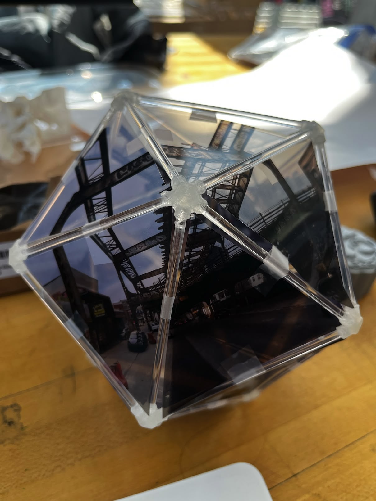
The problem is that we didn't figure out a way to gracefully mount triangle sheets of film on top of the icosahedron faces. In the prototype, we just taped the film to the it as a temporary solution.
The Plan
I want the triangle to slide into potentially some slit on the beam to stay in place. The width of the slit needs to be very very thin, paper thin. Another thing I want to keep about the previous prototype is that we try to make each part as transparent as possible: the joint connectors are printed with PETG Clear filament, and the beams are just clear acrylic rods. SLA resin printing just felt like a perfect thing to try to get both fine details and transparency.
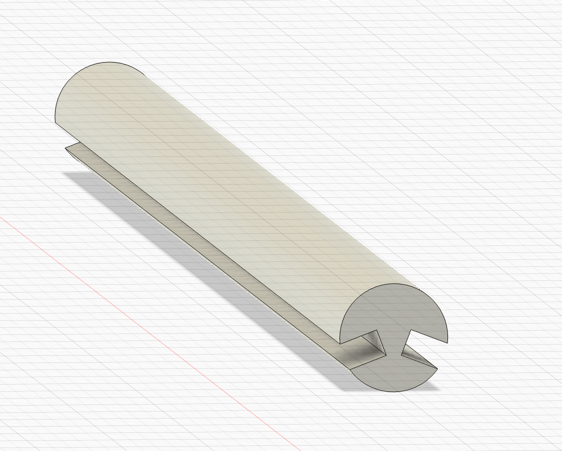
Modeling the Rod
Along the process, I made so many iterations of the design, a few are because of the difference precision and tolerance of the different printing materials and processes. I'm glad that I started off with everything parametrically so that I have a lot of flexibility to tweak the design later on.
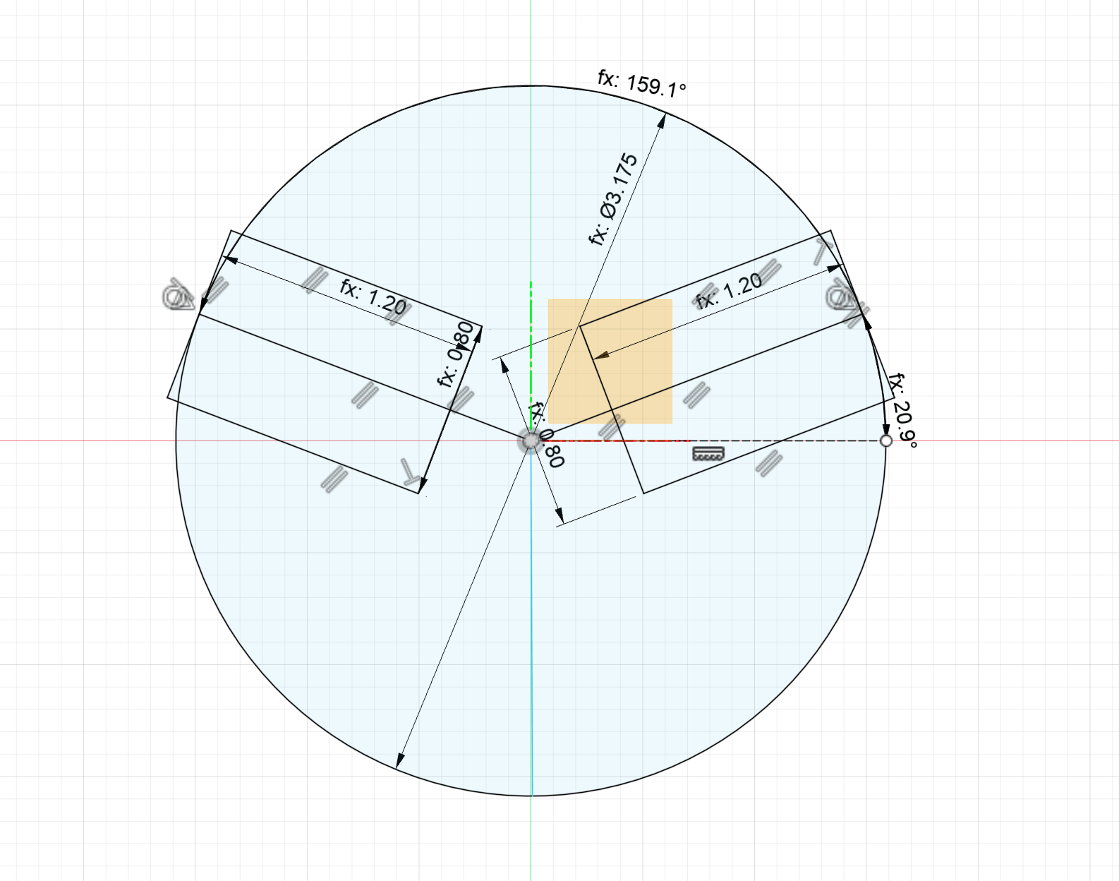
Here's the parameters for the rod model.
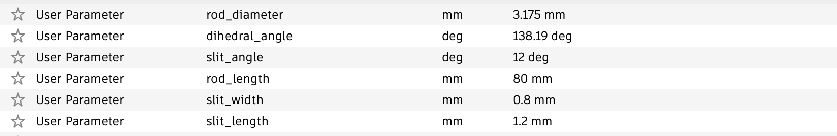
Parameter | Value | Note |
|---|---|---|
rod_face_diameter | 3.175 mm | |
dihedral_angle | 138.19 deg | |
slit_angle | 12 deg | Not being used |
rod_length | 80 mm | |
slit_width | 0.8 mm | |
slit_length | 1.2 mm |
Printing the Rod
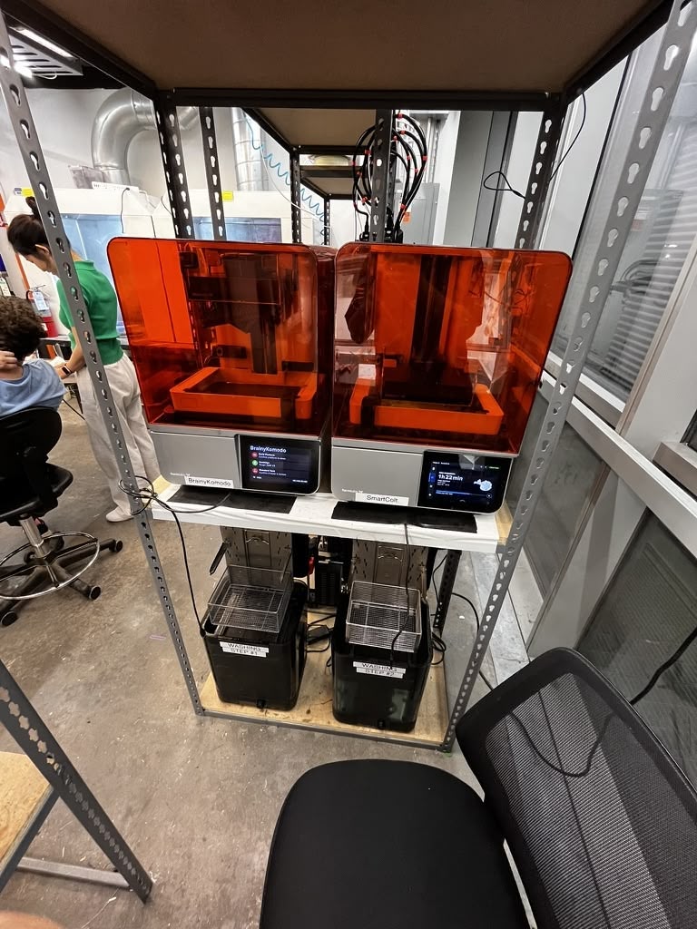
I'm using Formlab Form 4 with Clear V5 material. I asked Dan to give me a walkthrough of the printing process and Ceci helped me a lot with her fabrication knowledge. Here are the steps I followed:
- Check the build platform
- Print with patience
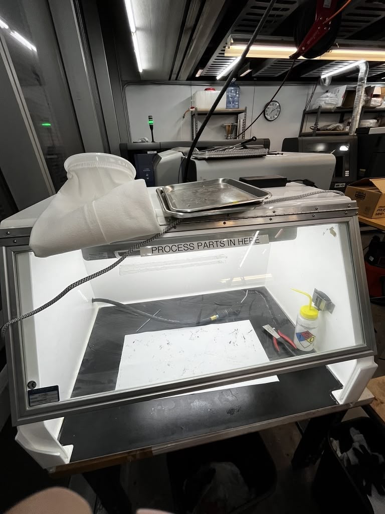
- Wash with IPA in Bath #1 with plate
- Separate the prints from the plate, blow the plate dry and put it back
- Wash the prints with IPA in Bath #2
- Remove the support from the prints
- Cure the prints with UV light
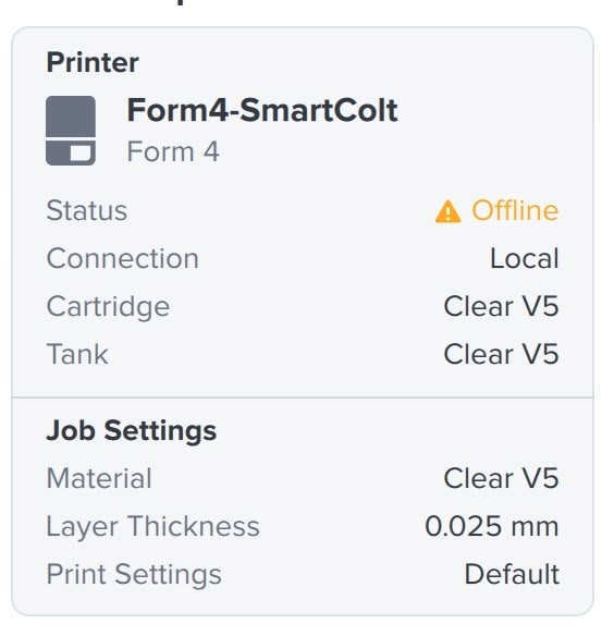
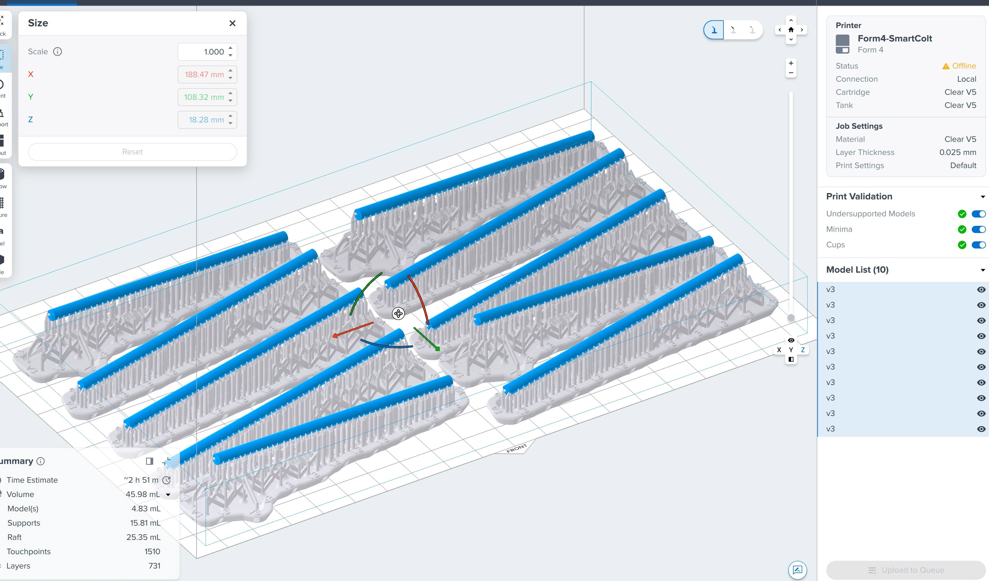
I started printing the first batch of rods. Here's the setting for the print. Mainly the layer height is set to 0.025mm to get the fine details.
In the same batch, I also printed some connectors (modeled by Shuang Cai in June 2025). I noticed the print time doesn not increase much when addinbg the connectors in because the SLA printing uses exposure and only the maximum height would affect the print time. Shuang sent me an STL file, and the exact dimensions is not captured in the file. I had to manually set the scale to be roughly correct (0.118x scale of the original STL).
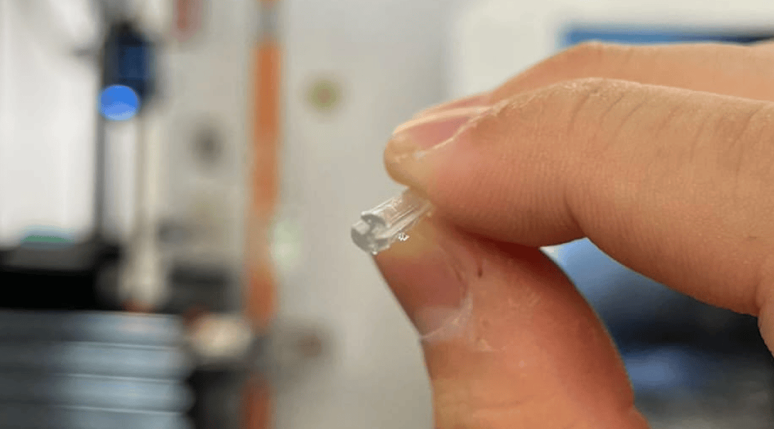
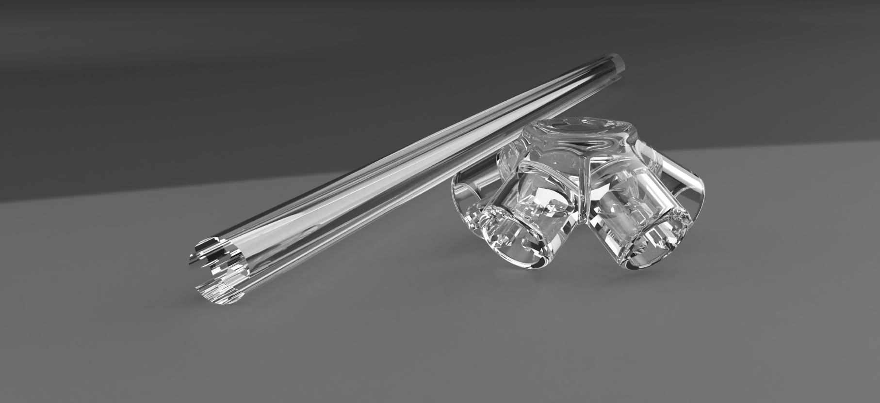
Here's my first print with SLA resin.
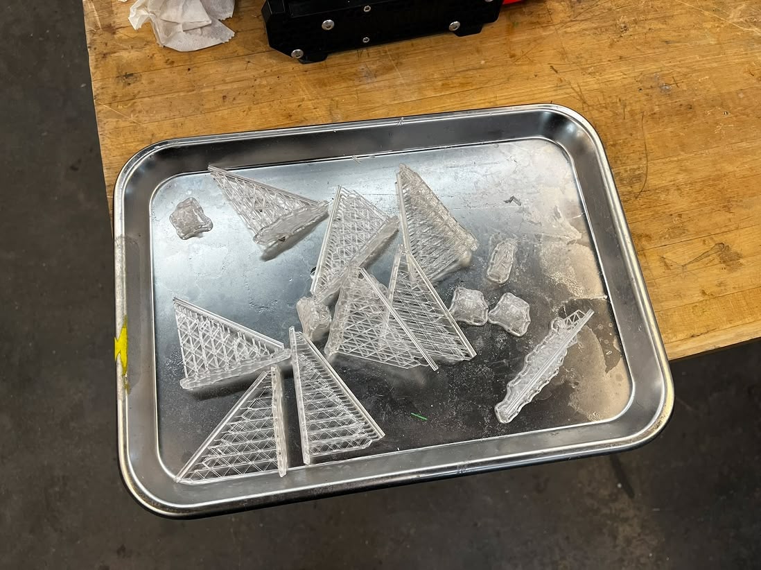
The side of the rode looks very nice and slit is very defined and definitely fits a piece of paper.
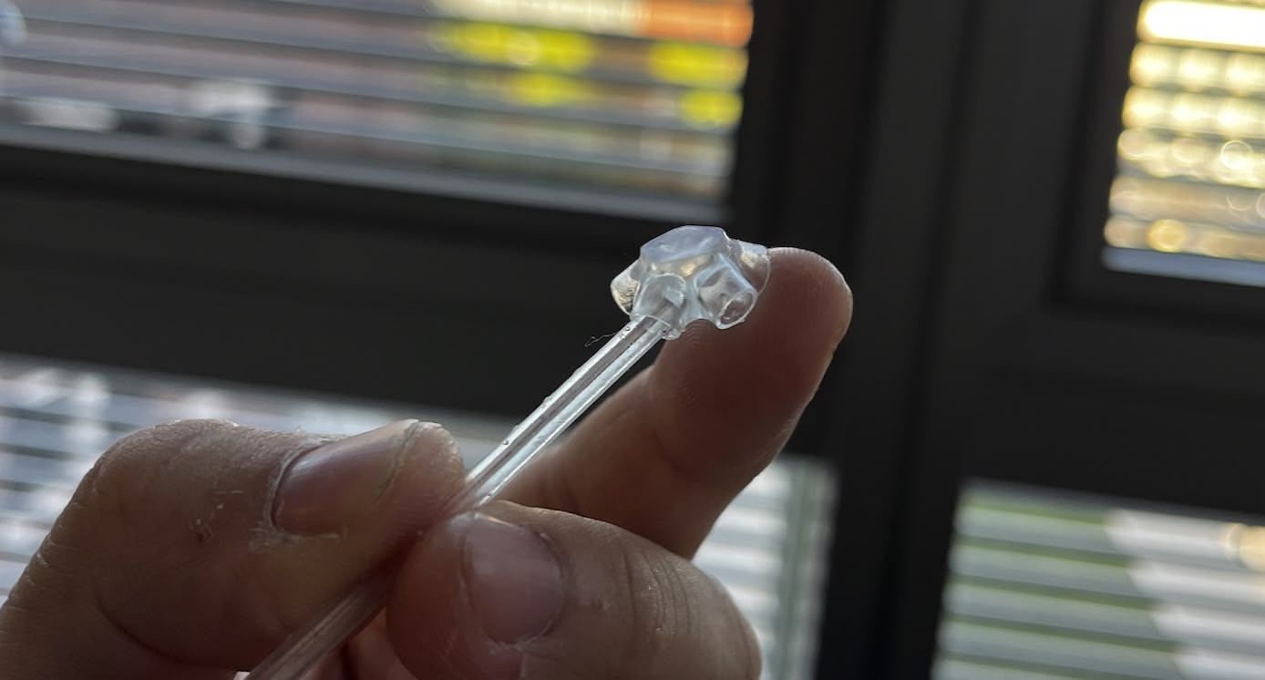
However, the connectors ended up too big for the rods to fit into. At this point, I felt the necessity to remodel the connectors, because I want full control over the design, specifically the dimensions.
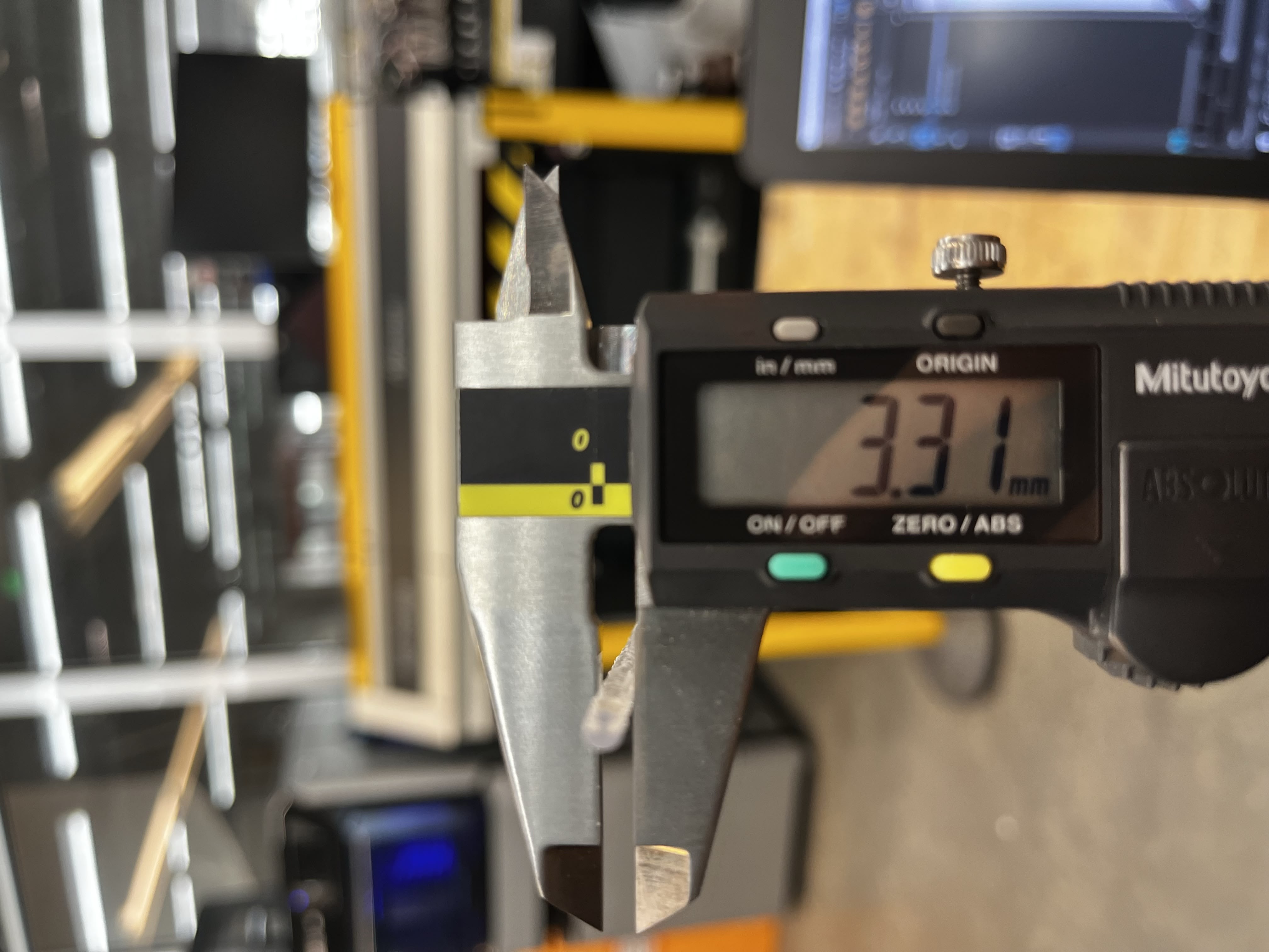
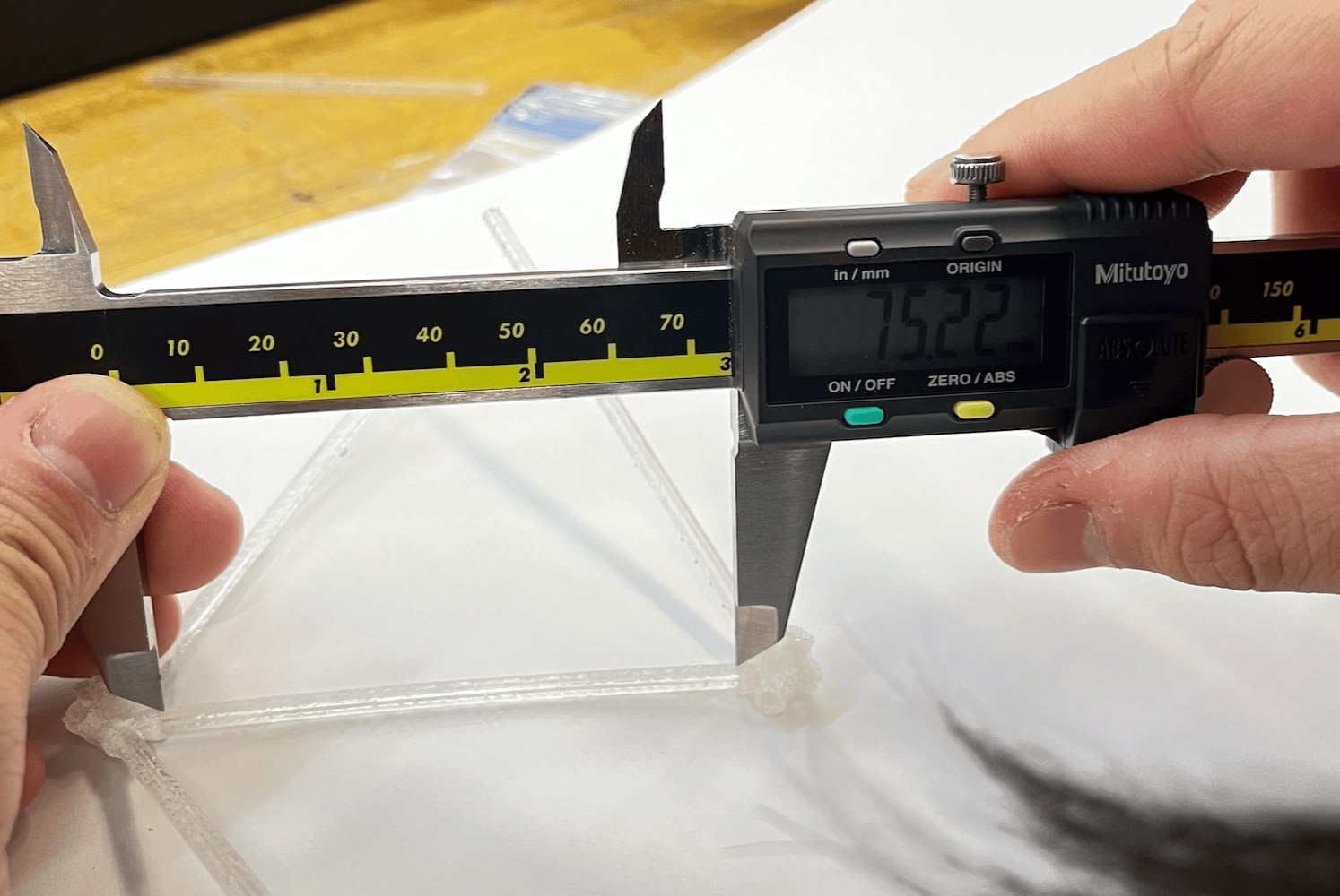
Another thing I noticed is that the true diameter of the rod is slightly larger than the designed diameter (3.175 mm). It reads on the caliper as 3.31 mm. I didn't want to change the rod design, so I'll compensate for the difference in the connector design.
Modeling the Connector
I didn't know exactly how to model the conenctor because the angle of each tube on the conenctor is quite tricky, as mentioned in Week 2 assignment. I found a video on YouTube that shows how to model an icosahedron (not the connector) in Fusion 360. And I learned the core skill of 3D Sketching in Fusion. I was able to acquire the mathmetically accurate angle for each tube by setting up geometry constraints.
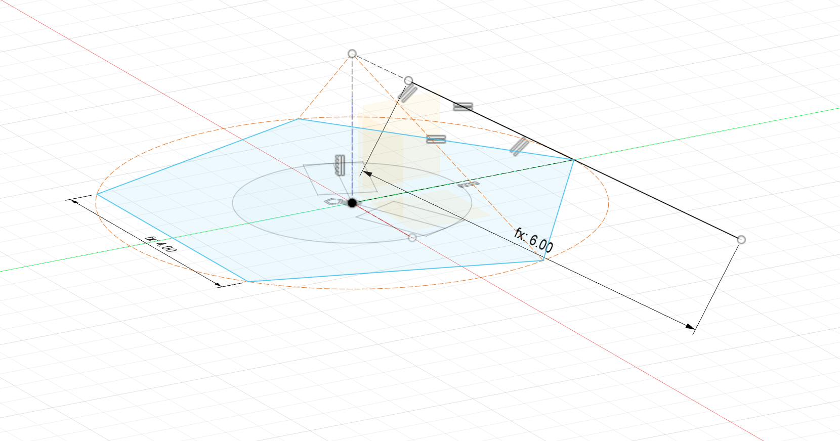
Currently the tube is in a line form. To make it into a 3D body, I used the "Pipe" tool to make a cylinder along that line.
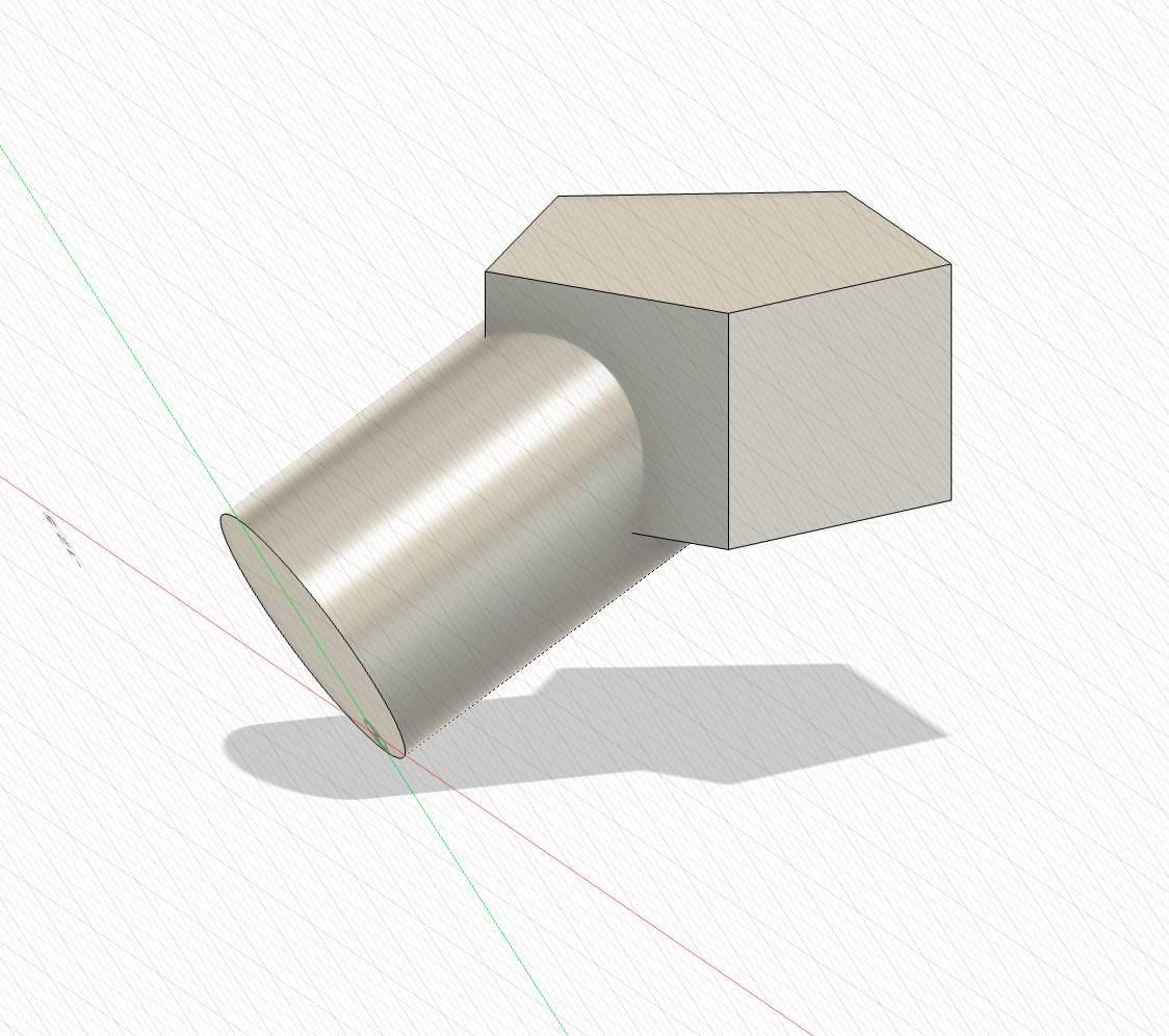
I then copied over the rod face sketch to the face of the tube to push in on the cylinder and make a hole.
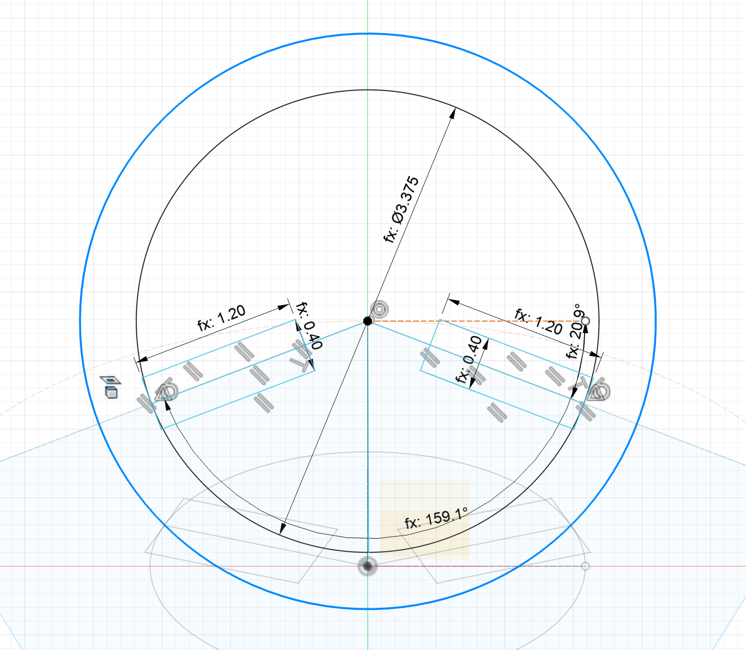
Having learned that the material turns out bigger after printing, I also made a few variables for tolearnce clearance and subtracted the numbers from the inner diameter of the tube and the slit width. This is why the diameter of the shape is 3.375 mm instaed of 3.175 mm.
Then I run a circular pattern for the tube to create the other four, merged the tubes with the pentagon block, and then fillet all the edges to make to smoothy and nice.
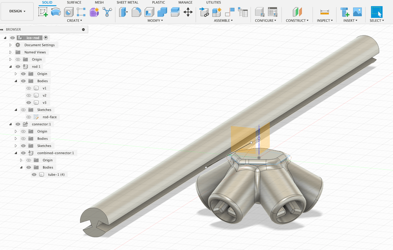
I also learned how to render the model in Fusion 360. I applied the clear acrylic material to both parts.
Printing the Connector
I'm still worried about the clearance of the connector, given how rigid the resin material is. That's why I'm trying FDM printing with both PETG and PLA filaments. All the FDM printer setting are the same, which uses 0.2mm layer height and half the default speed for the "Structural" profile that came with Prusa.
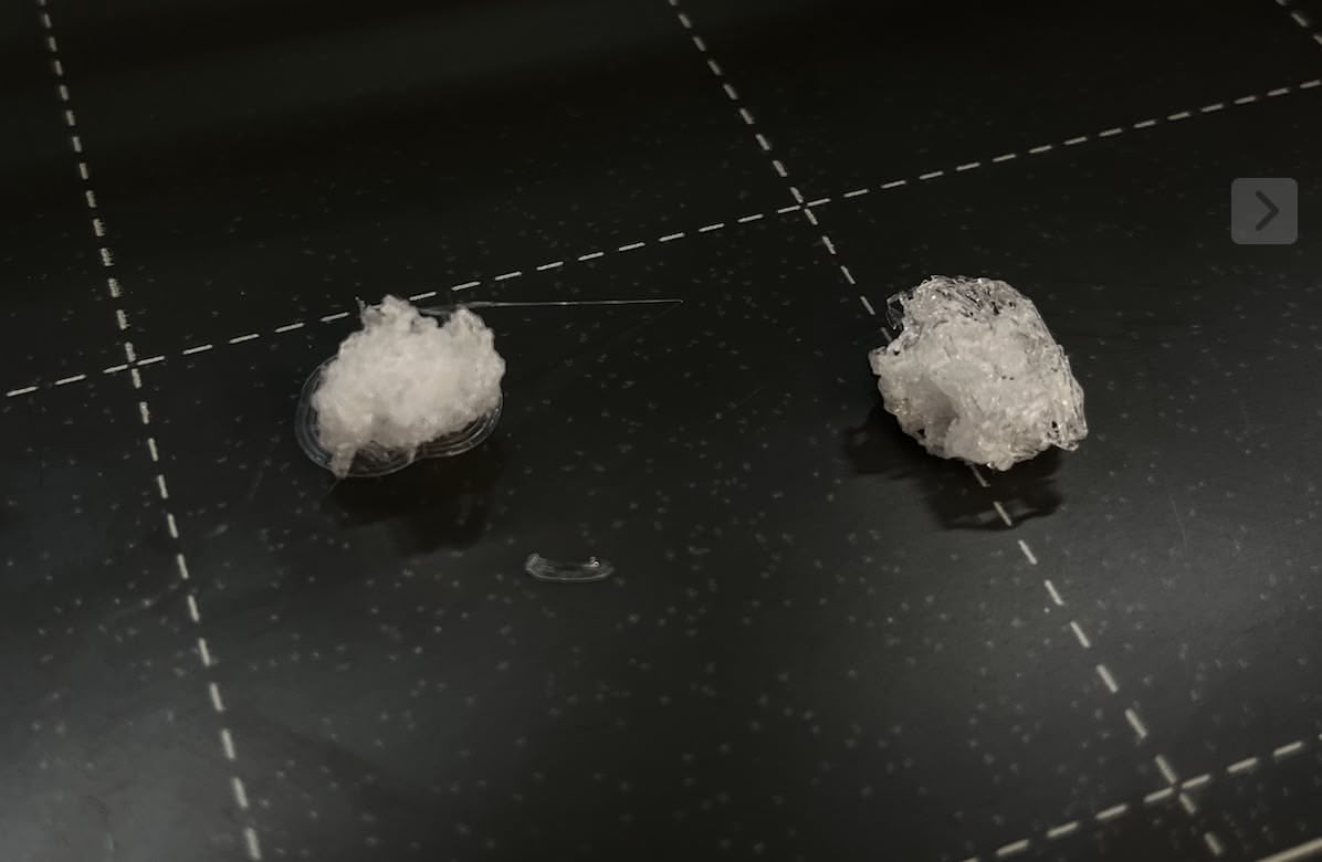
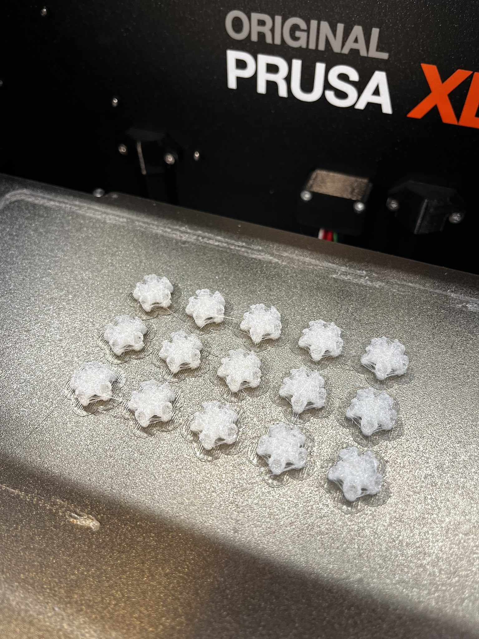
The prints turns out really fuzzy and stringy and I consulted Dan again about it. This is probably due to moisture in the air and the material. None of them are usable. The CBA shop needs some maintenance.
Then, I noticed someone is using TPU filament on the Prusa XL, which allows the product to be flexible. Some of these materials are kept in separate dryer box on the top of the printer. I think the flexible material is a good idea for the fit and also for the ease of assembly and I decided to try it.
You can see the final print is still a little stringy, but much better than the PLA and PETG. The TPU tubes can stretch a little bit when I connect the rod.
Before Assembly
Before going forward to assemble, I need to print more rods. To assemble the entire icosahedron, I need 30 rods and 12 connectors. I'm missing a few rods, so I need to print more with the SLA resin printer.
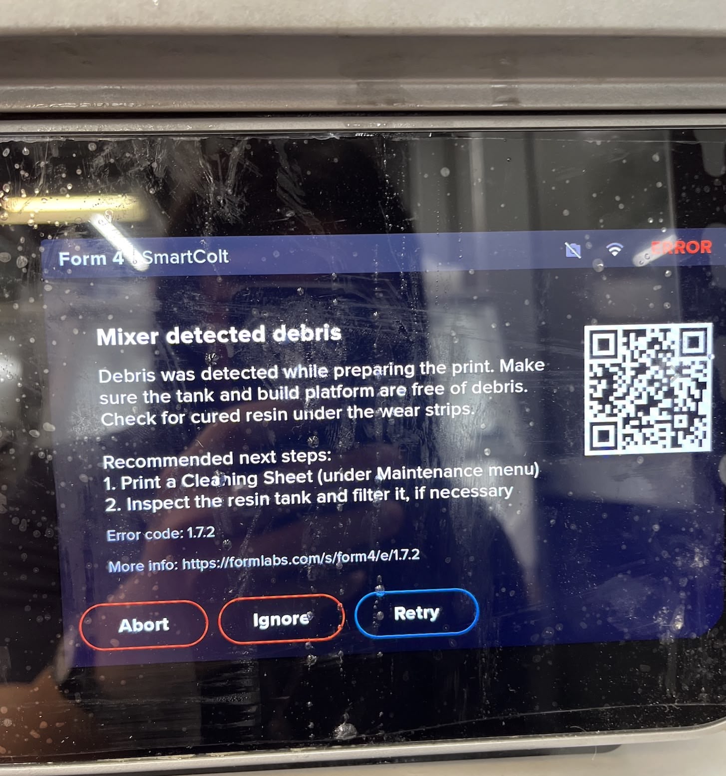
Some SLA Printer Failures
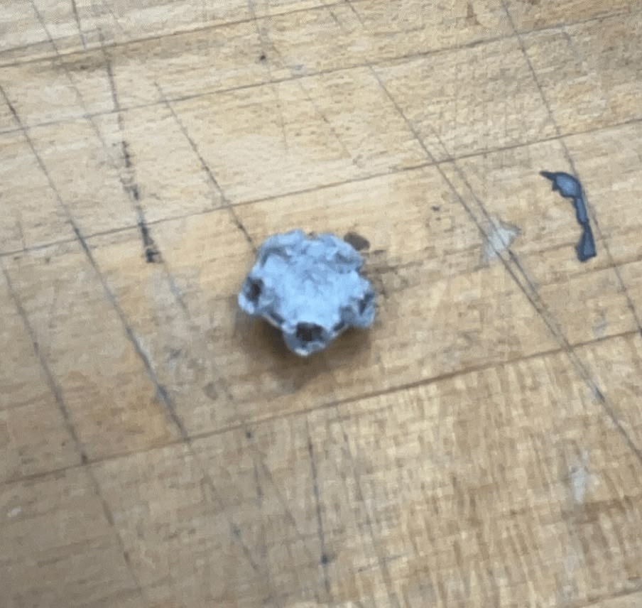
Unfortauntely, the SLA printer is showing warning about "Mixer detected debris". Although I found the official youtube cleaning guide from Formlab, I notified Dan about it and he's going to clean it up. The previous print by someone else is a good example of the effect of the debris - it failed miserably.
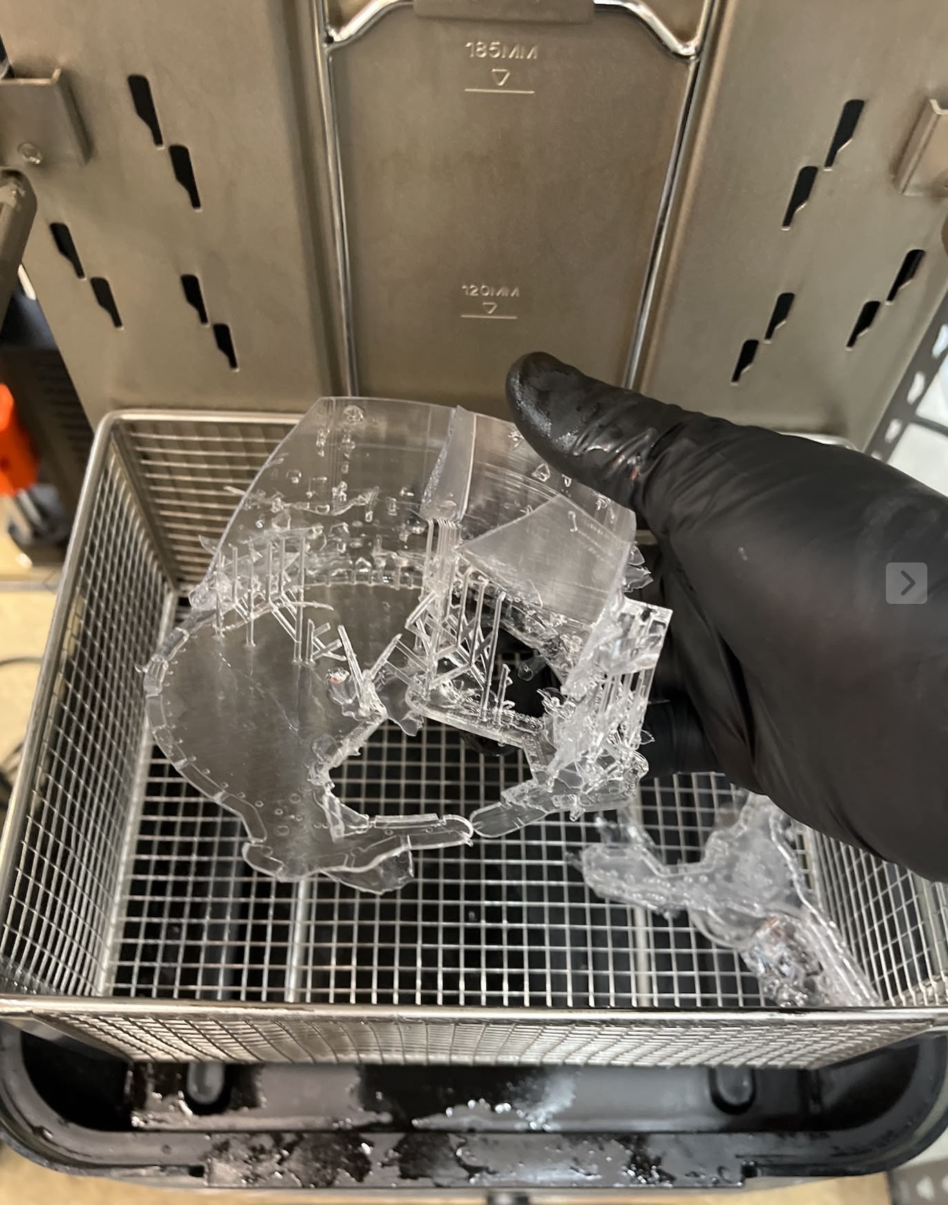
I waited a few days until Dan swapped out the resin tank to a new one. I printed a few more rods again with the SLA resin printer.
It turns out that the support material was too close to the slits, so it required a lot of cleaning. Here's a 10x speeded up time lapse of the cleaning process.
Film dimensions
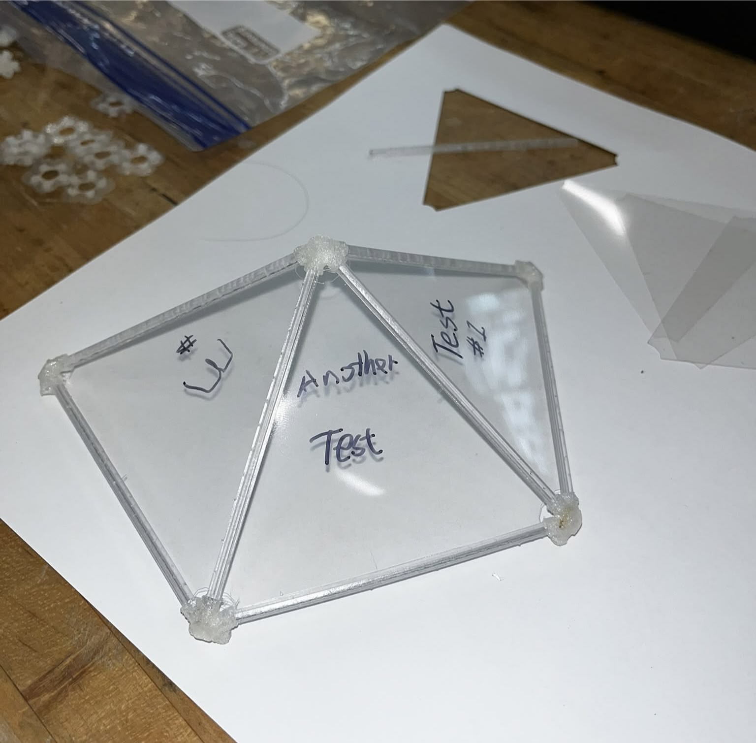
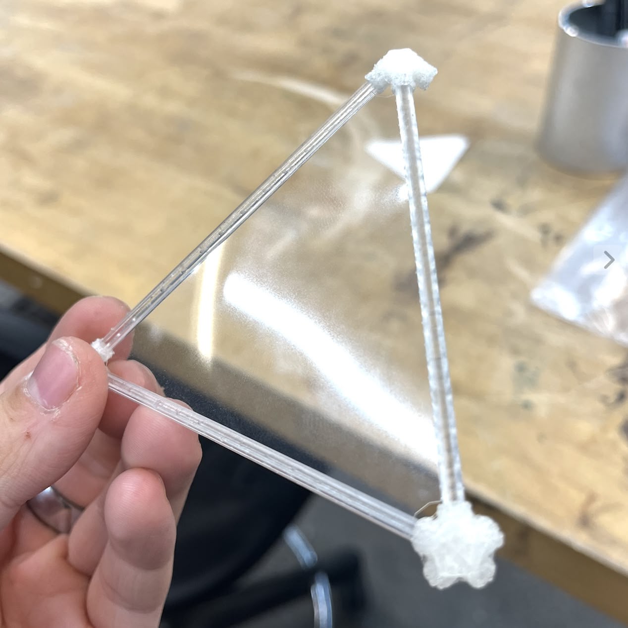
Now I have one triangle face assmbled (with 3 rods and 3 connectors).
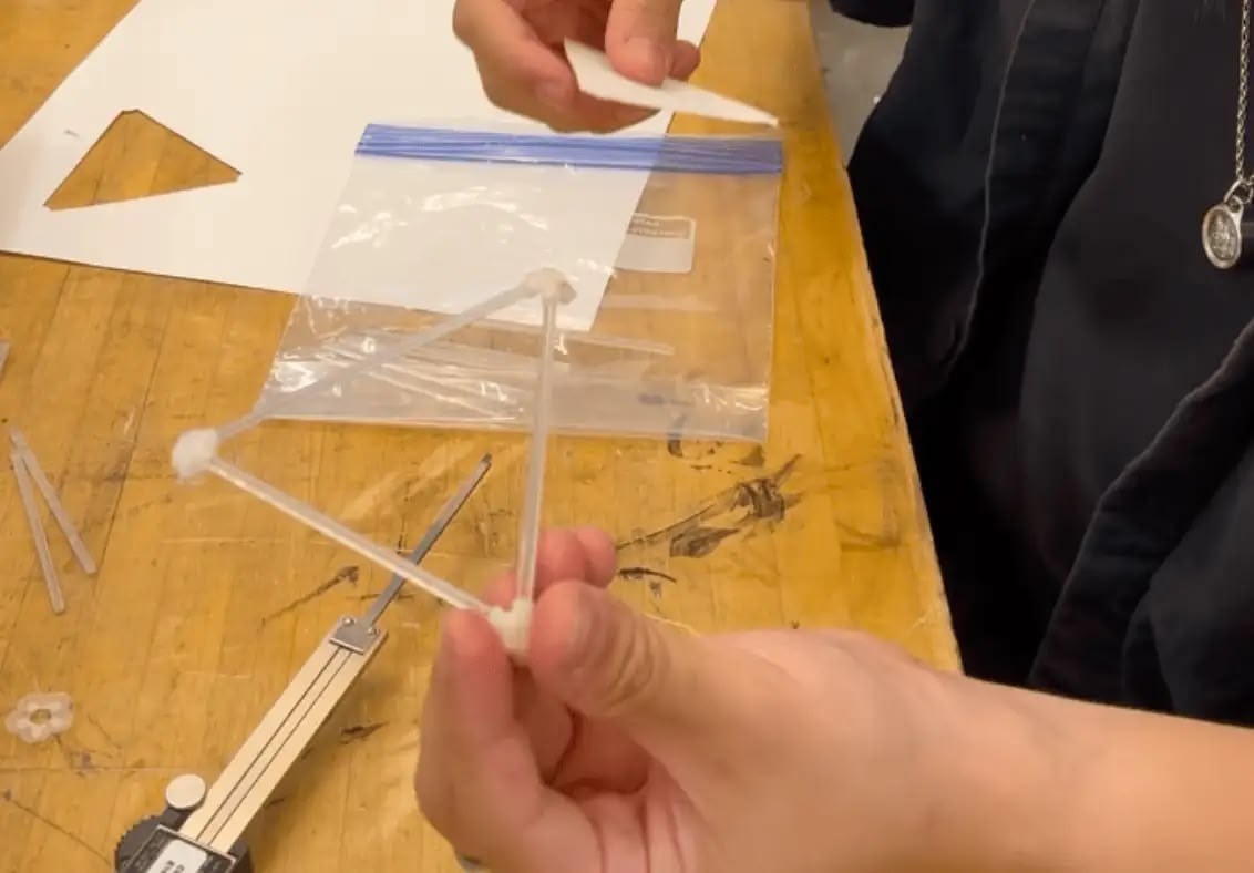
Now I need to figure out the actual dimension for the triangular film piece inside. I took a measurement of the actual distance between the assembled connectors on both sides of the rod, which reads ~75mm.
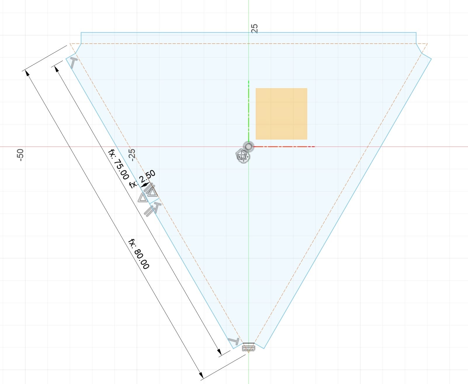
I went back to Fusion 360 and modeled the triangle shape for the film. Given the entire rod is 80mm long, I made a notch at each corner of the triangle to make the tabs that slide into the slots 2.5mm wide.
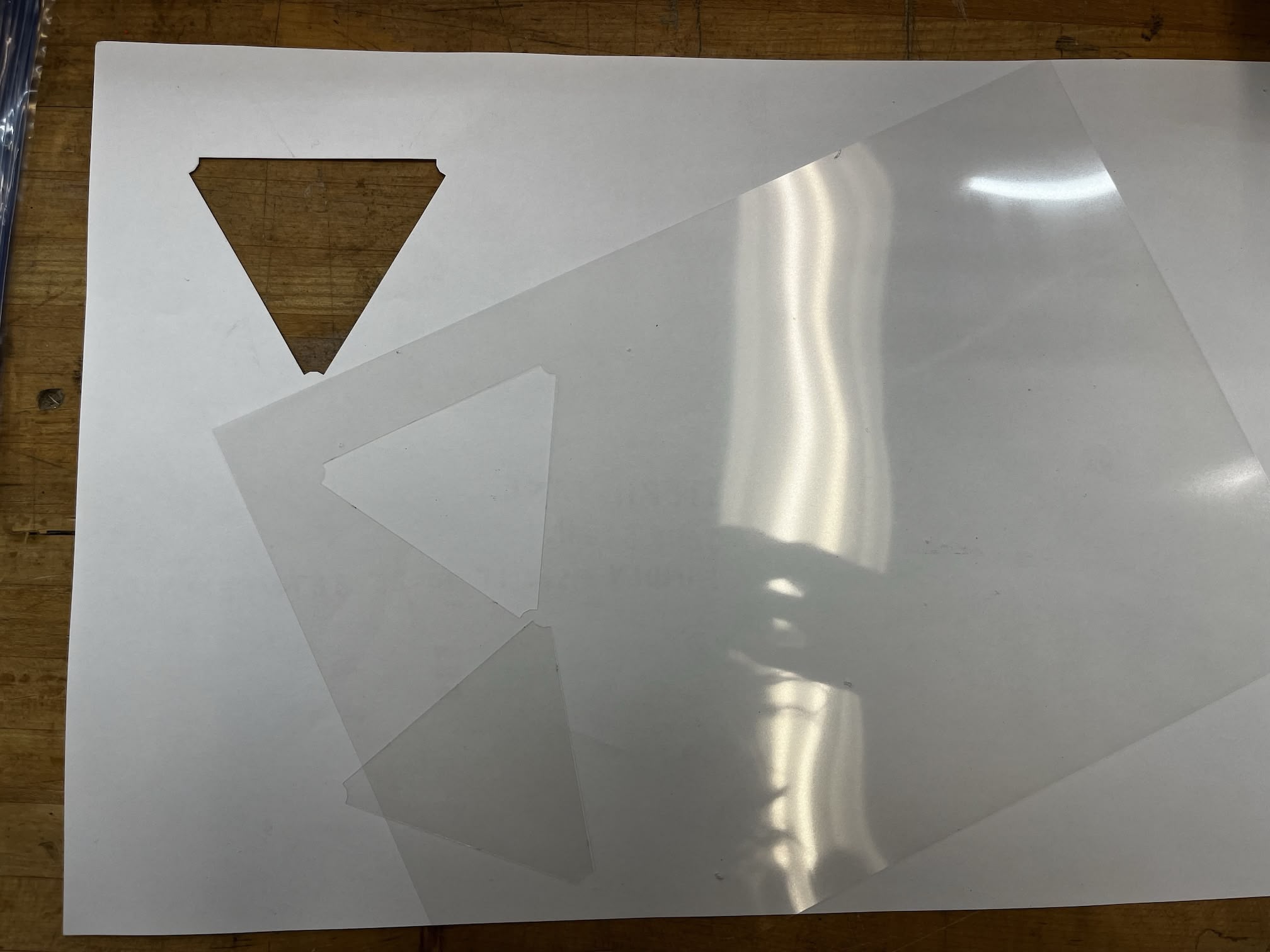
I then used the xTool laser cutter to cut out the triangle shape for the film.
Final Assembly
The assembly takes some skill and patience. The film needs to be perfectly aligned with the rod and the connector, and the tab (after some adjustments) can be pushed into slit on the rod smoothly after some maneuvering.
I assmbled two adjacent triangle faces and now the icosahedron looks like this.
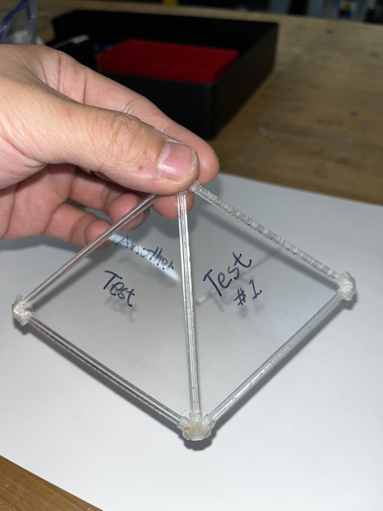
Here's three faces assembled.