Assignment
- group assignment
- use the test equipment in your lab to observe the operation of an embedded microcontroller
- individual assignment
- use an EDA tool to design an embedded microcontroller system using parts from the inventory, check its design rules for fabrication, and simulate its operation
- extra credit
- try another design workflow
- design a case
Something useful for the final project
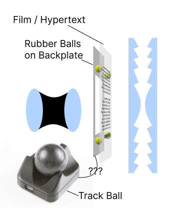
As previously mentioned in my first week's post, I'm planning to make a version of Memex by reimagining the modern web browser experience with low tech. One of the key components is the scrolling mechanism, which I'm imagining to use a trackball device to control the scrolling. After some googling on the optical sensor for the trackball (I've thought about purely mechanical solutions like a wheel or a ball, but this part of the class is about electronics so here we are), I found the PixArt PMW3360 sensor.
PixArt PMW3360
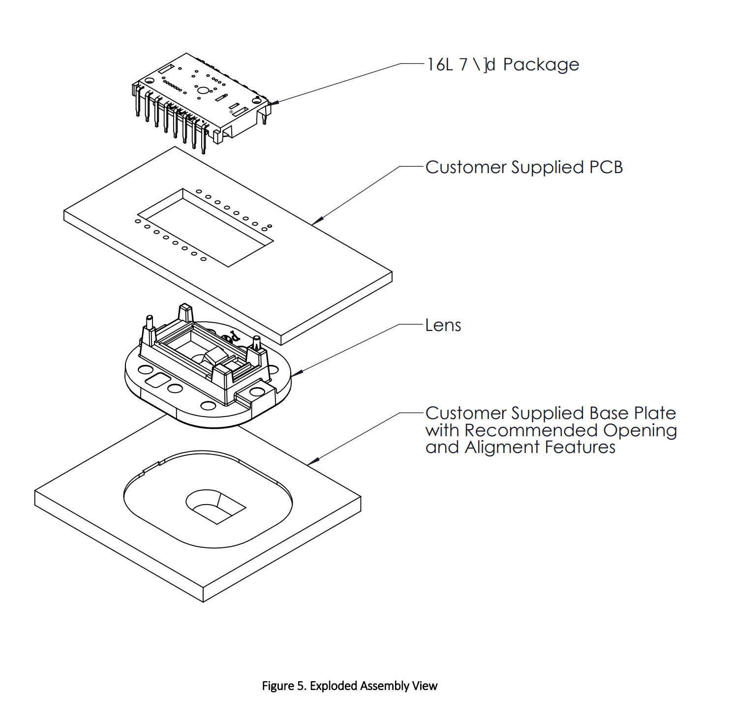
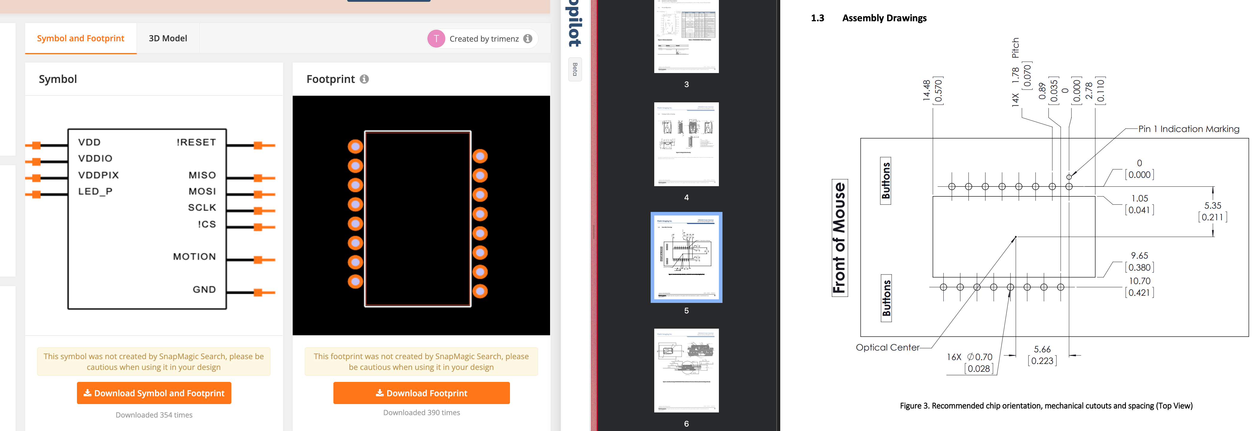
PixArt PMW3360 is an optical mouse sensor found in many mice and trackballs. Here's the datasheet for the PixArt PMW3360 sensor. On page 8, it seems that the sensor comes with a chip and a lens, but the customer will have to supply their own breakout PCB and base plate for the lens.
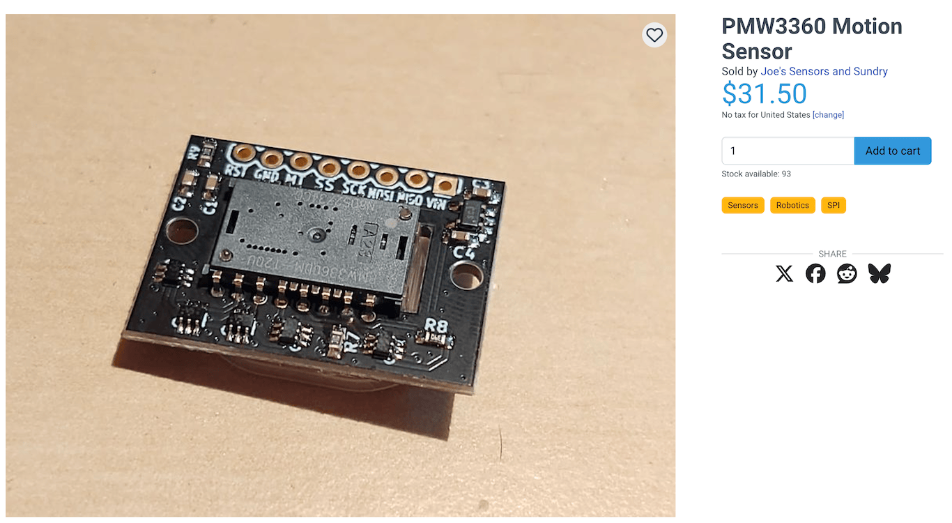
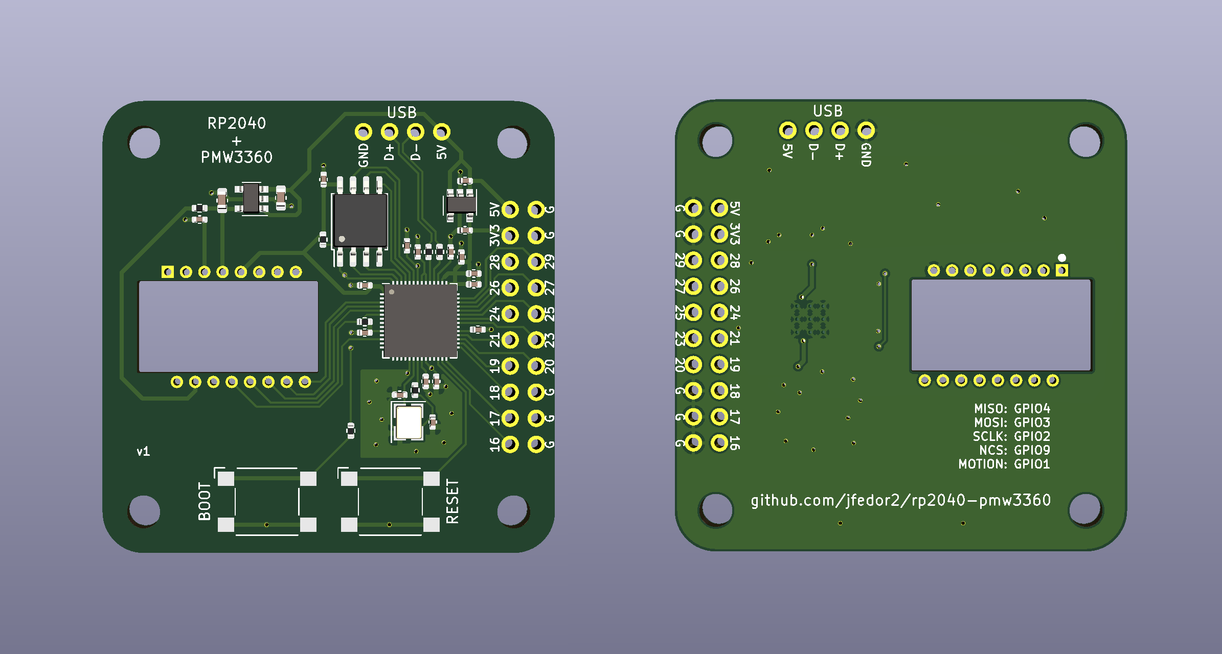
There are a few vendors that sell the sensor with their own breakout PCB, for example Joe's Sensors and Sundry on LECTRONZ.com. Although I'll probably opt for a bare sensor from AliExperess, in the spirite of the class, I do appreciate their open source effort in designing the breakout PCB. I also stumbled upon a few other open source PCD designs, such as this one by kbjunky, and this one by jfedor2 (specifically for the RP2040).
These open source designs saved me a lot of time reading the datasheet and understanding the sensor.
I also found a symbol and footprint for the sensor on SnapMagic created by trimenz. After eyeballing the footprint against the datasheet, the schematic is missing some pins for reason I don't know. So I'm not using it.
KiCad
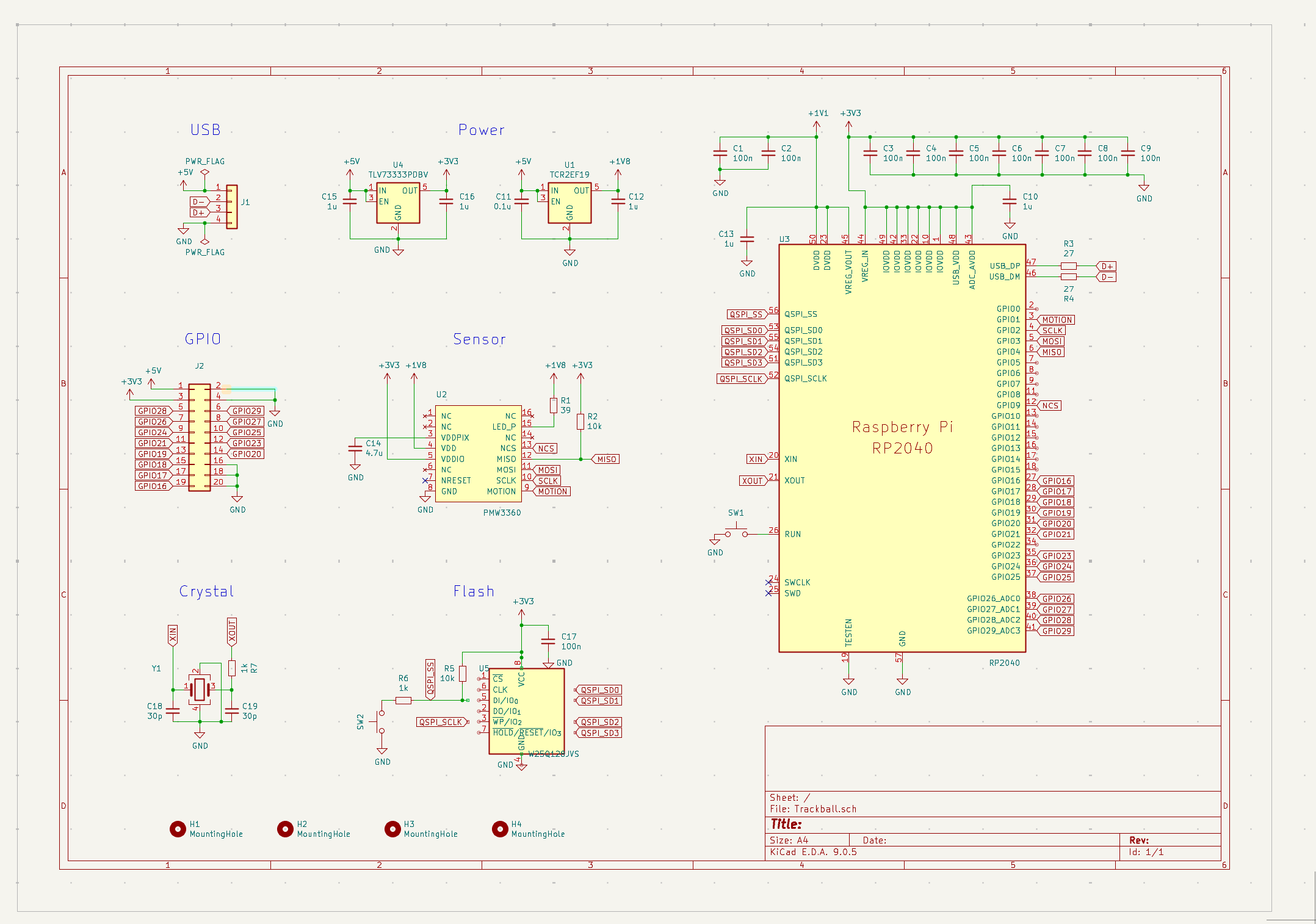
Because of my limited experience (all of my experience is limited to Quentin's recitation), I decided to take a look at jfedor2's kicad project file.
The schematics has quite a some additionalparts - flash, crystal, GPIO pins breakout, etc. I'm not sure exactly what they do yet. My plan is to modify this open source schematic to fit my XIAO RP2040 board.
Studying the Sensor Schematic
I started by looking closely at the sensor schematic. I'm cross referencing the datasheet and the symbol from jfedor2's kicad schematics file.
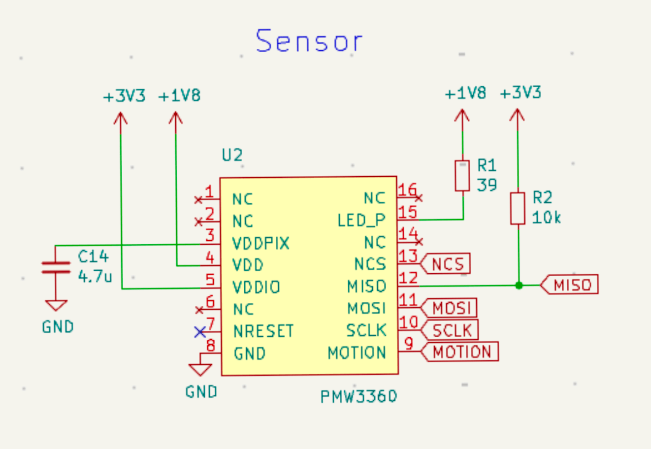
I noticed a few things:
- PWM3360 uses Serial Port Interface (SPI) to communicate with the microcontroller.
- MISO, MOSI, and SCLK are connected to the corresponding pins on the microcontroller.
- The
NCSpin meansNot Chip Select. It's used to select the sensor is software controlled. So I can connect it to any GPIO pin on the microcontroller.
- The sensor needs 1.8 - 2.2V power supply, which is not supplied by the XIAO RP2040, which means we need a voltage regulator to step down the voltage.
Regarding the additional parts, here's my thinking:
Part | Function | Necessary for my project? |
|---|---|---|
Flash | Store the firmware for the sensor | No |
Crystal | Oscillator for the sensor | No |
GPIO pins breakout | Connect the sensor to the microcontroller | No |
USB pins breakout | Connect the sensor to the USB port | No (XIAO RP2040 has USB) |
3.3V Voltage regulator | Step down the voltage | No (XIAO RP2040 has 3.3V) |
1.8V Voltage regulator | Step down the voltage | Yes |
Make the Changes
First,I removed all the additional parts and replaced them with the XIAO RP2040 and the 1.8V voltage regulator from the HTMAA fab inventory.
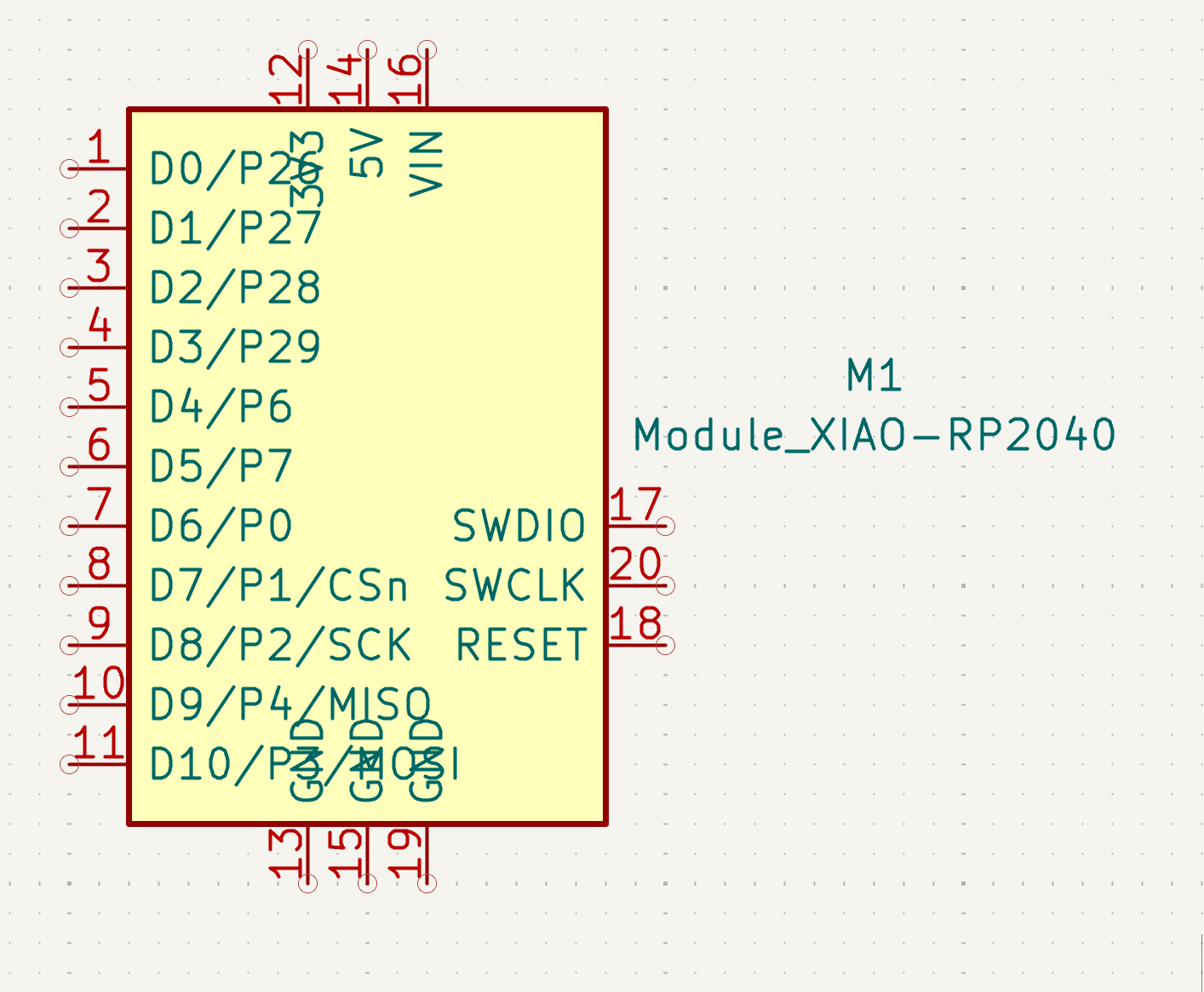
As suggested in the recitation, the first thing I did is to rename the pin labels in the symbol for XIAO RP2040 to include the actual P pin number, in addition to the D pin number.
Here are something present in the jfedor2's symbol but I couldn't find in the HTMAA fab inventory:
Part | Note |
|---|---|
1.8V Voltage regulator | I'll find an alternative that ships quickly to me in a good footprint |
100nF capacitor | I doubt that I need that much capacitance (it's at VDD pin, so it's for stability) |
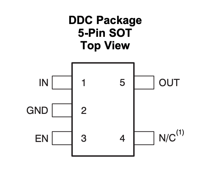
In mrjohnk's open source design, they are using a TLV70019DDCR voltage regulator (link on Digikey, datasheet link) and the package footprint is SOT-23-5 Thin.
For the series of parallel capacitors, I'm replacing them with a single 4.7uF capacitor.
After I made sure everything has the correct footprint, I then tried to connect everything in the PCB design. I had a lot of trouble with the connections.
Iterations
Version 2
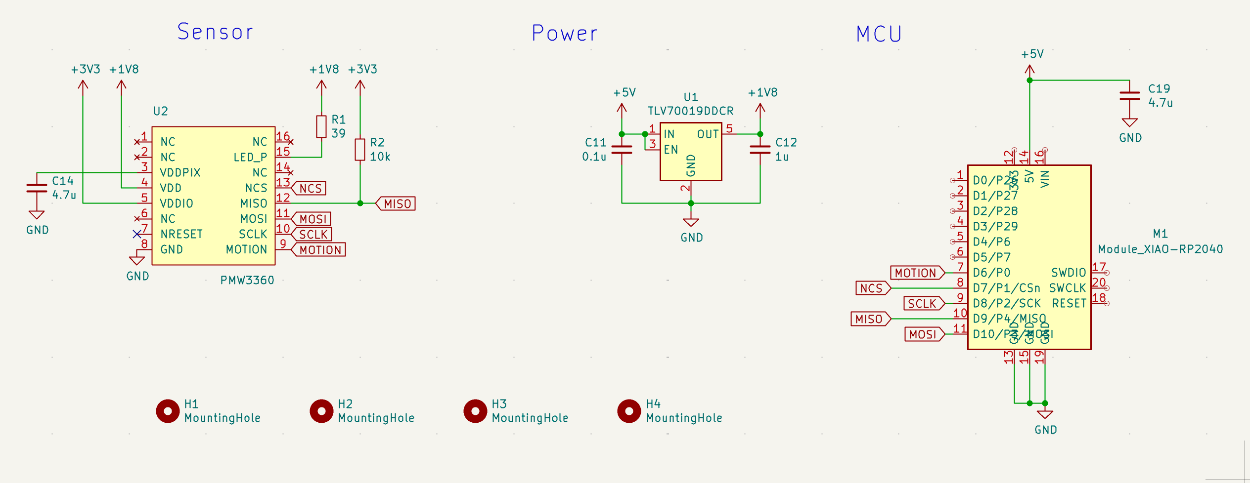
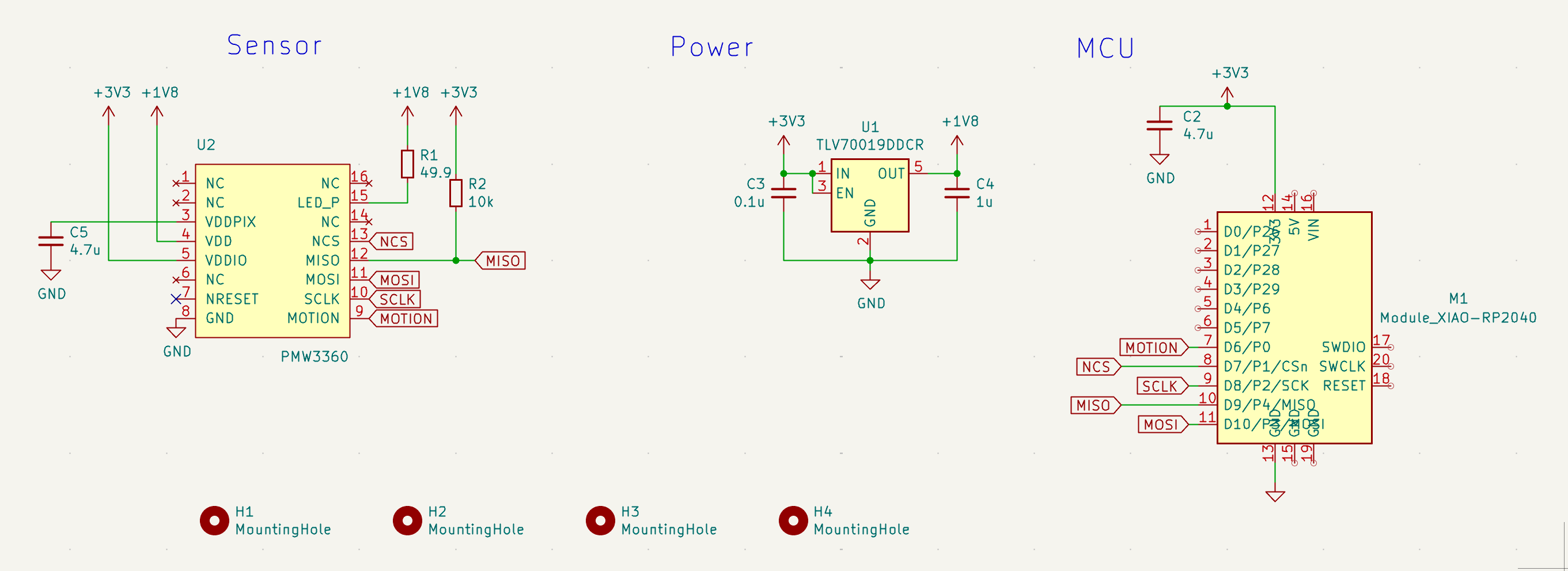
One of the challenges was because of the SPI pin order of the XIAO RP2040 and the PMW3360 sensor are different. I also noticed that TLV70019DDCR can take 3.3V input, so I disconnected it from 5V and hooked it up to 3.3V. The 5V power is not in use in this design. Here's the version 2 of the schematics.
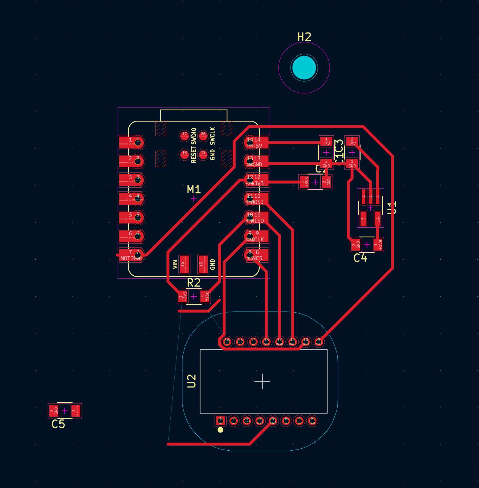
In the PCB design, I changed the orientation of the PMW3360 sensor because I want it to look more symmetric with respect to the XIAO RP2040 USB-C port, like a normal mouse / trackball input device.
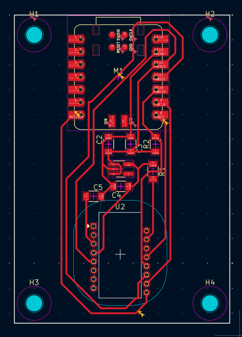
Unfortunately, something is missing in the above design: the ground connection for PMW3360 sensor is missing because the routing topology just doesn't allow it.
Version 3
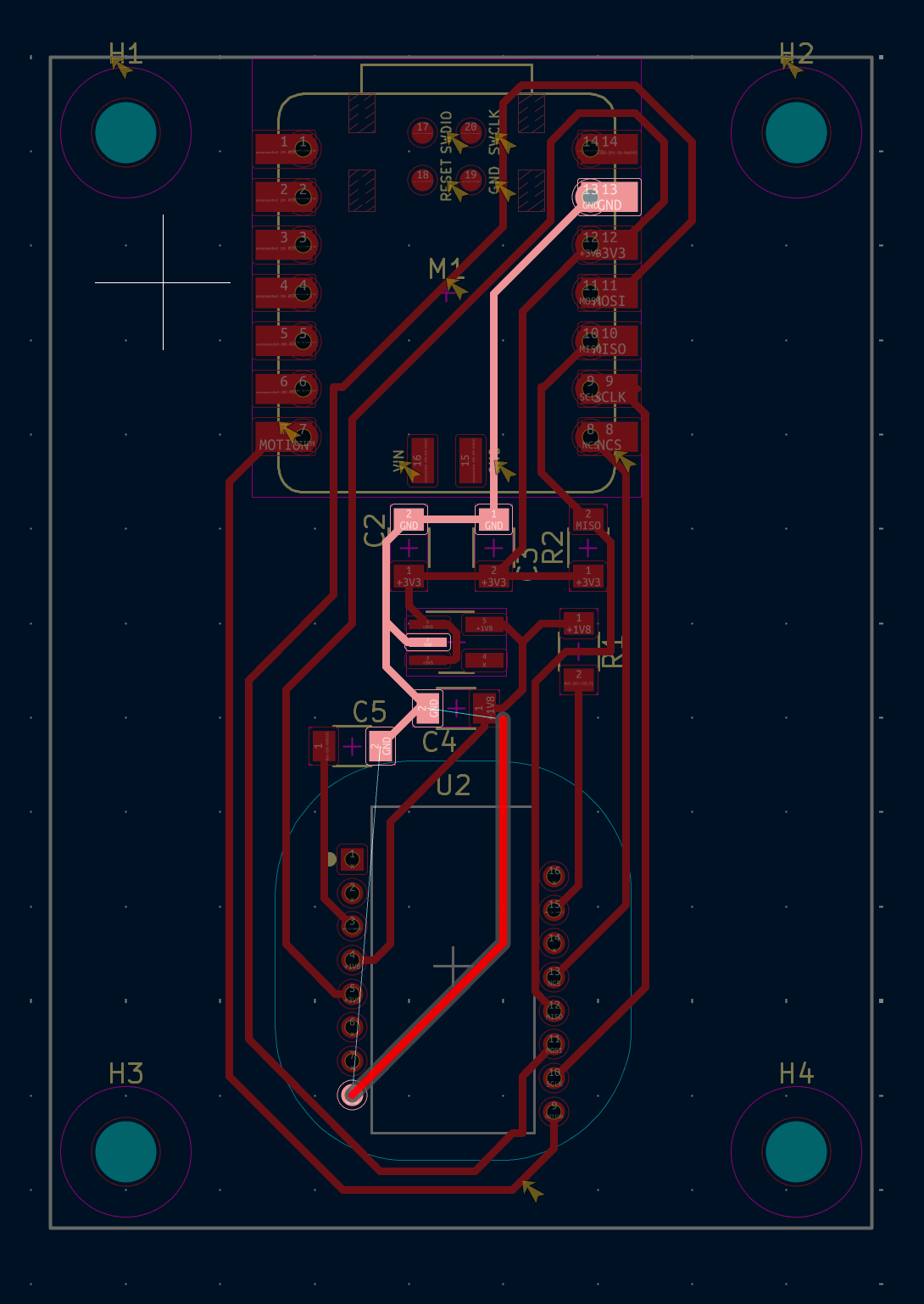
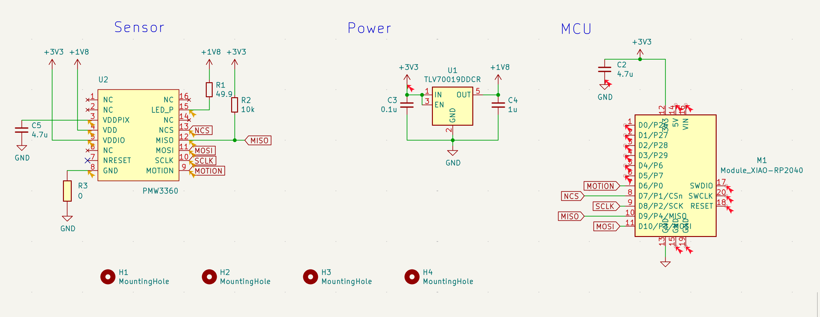
Therefore, I added a 0ohm resistor, basically a jumper, to connect the ground of the PMW3360 sensor to the ground of the XIAO RP2040. Here's the version 3 of the schematics.
Here's the version 3 of the PCB design, which passes the ERC check.
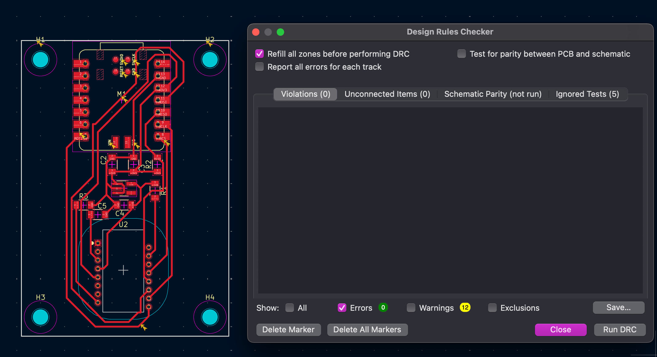
Last but not least, the PMW3360 sensor has, well, optical sensors at the bottom, so the PCB needs a cutout underneath the sensor (which is why I avoided any routing under the sensor as much as possible).
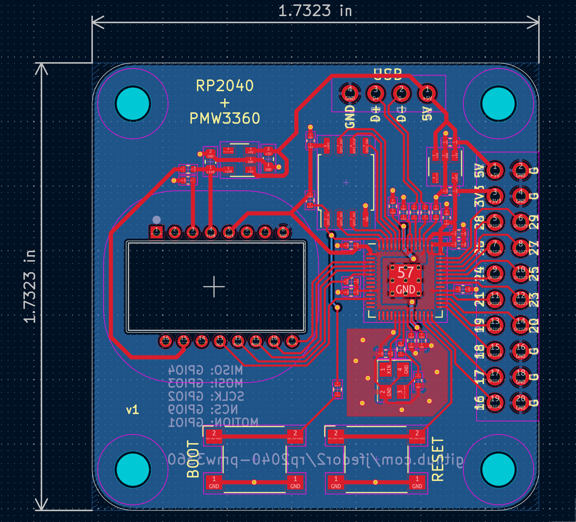
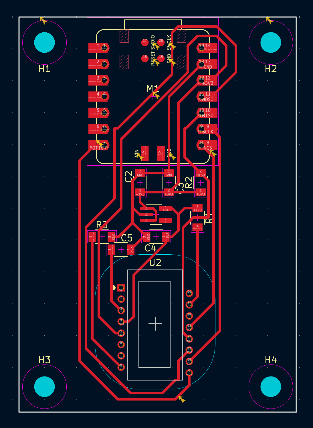
Final PCB Design
This is the final version of the PCB design.
And here's a 3D render of the PCB.
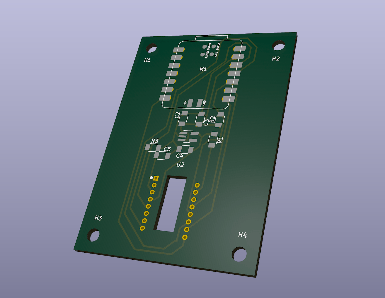
And here's the 3D model for the PCB for future case design.
References
- Quentin's EDA Recitation
- Seeed Studio XIAO RP2040 Schematic
- jfedor2's kicad project file
- mrjohnk's open source design
- SnapMagic
- PixArt PMW3360 sensor datasheet
- TLV70019DDCR
- TLV70019DDCR datasheet