Assignment
- characterize your lasercutter's focus, power, speed, rate, kerf, joint clearance and types (group work)
- design, lasercut, and document a parametric construction kit, accounting for the lasercutter kerf, which can be assembled in multiple ways
- extra credit: include elements that aren't flat
- extra credit: engrave as well as cut
Characterizing the Laser Cutter
Cardboard Thickness
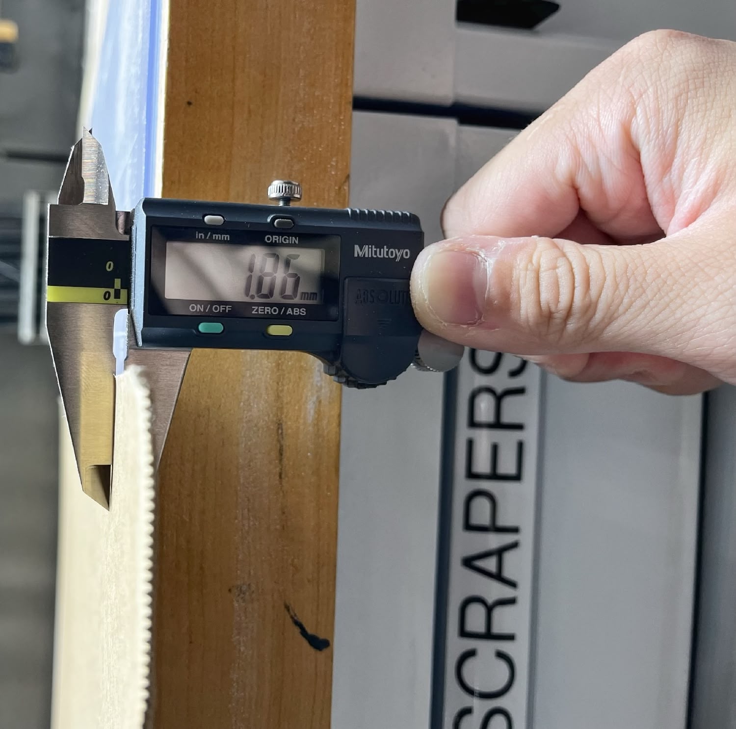
Before I characterize the laser cutter, I need to know the thickness of my cardboard. I found some pretty thin cardboard underneath the laser cutter workspace, and the thickest one I found is ~1.85mm.
Out of the two laser cutters in the lab – an old Epilog machine that requires CorelDraw and a new xTool machine with amazing software and UX – I chose the xTool machine.
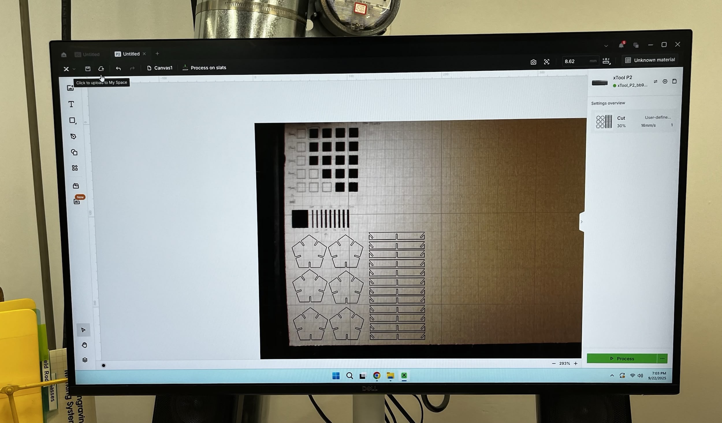
Power and Speed Characterization
I started testing different speed and power settings to see what works best for cutting this specific cardboard.
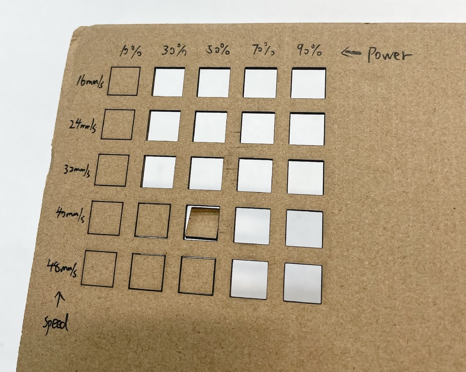
Here's the table of result of whether or not the cardboard is cut through:
Speed ⬇️ / Power ➡️ | 10% | 30% | 50% | 70% | 90% |
|---|---|---|---|---|---|
16mm/s | No | Yes | Yes | Yes | Yes |
24mm/s | No | Yes | Yes | Yes | Yes |
32mm/s | No | Yes | Yes | Yes | Yes |
40mm/s | No | No | Yes | Yes | Yes |
48mm/s | No | No | No | Yes | Yes |
The result shows that faster laser weakens the power. I don't want things to burn out, so I chose the lowest power and speed that can still cut the cardboard, which is 30% power and 16mm/s.
Kerf Characterization
Laser beam has a certain width, which means when the laser cuts the cardboard, say for a 2mm wide slit, the actual cut width is 2mm + kerf. Nowing my material is 1.85mm thick, I made a few rectangular slits with widths around that thickness.
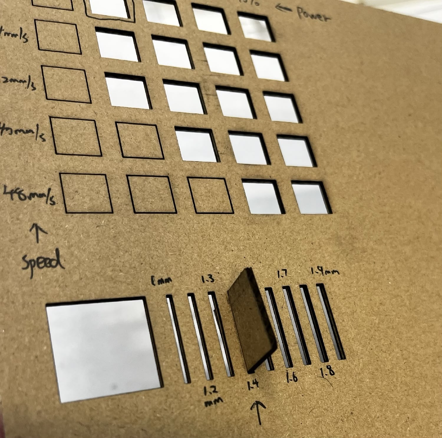
Here's the table of result of the cut width and how tight the fit is. N/A means the cardboard cannot fit in the slit without significant force.
1mm | 1.2mm | 1.3mm | 1.4mm | 1.5mm | 1.6mm | 1.7mm | 1.8mm | 1.9mm |
|---|---|---|---|---|---|---|---|---|
N/A | N/A | N/A | Tight Fit | Tight Fit | Fit | Fit | Fit | Fit |
Both 1.4mm and 1.5mm are tight fits, but 1.4mm is a bit tighter. I will be using 1.4mm for the joint width for the future CAD design.
Icosahedron Joints / Beams Kit
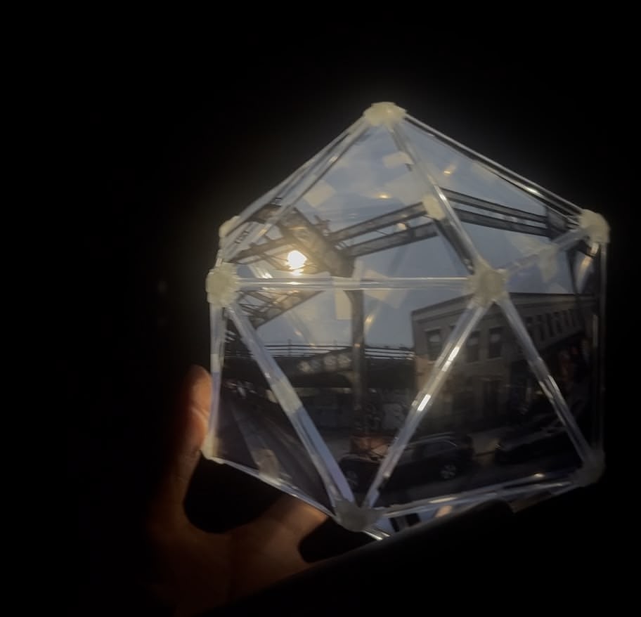
I want to design a bunch of pieces that can be assembled into an icosahedron. Previously, I've used 3D printing to manufacture the joints (with the help of Icosahedron Printed Joints Generator and Shuang Cai), and used off-the-shelf acrylic rods for the beams. For this past project, it's important that the parts are transparent, because light needs to shine through the icosahedron as much as possible, projecting the panoramic images on the film out.
For this HTMAA assignment, I think it would be possible to design a flat kit version to assemble an regular icosahedron. For each joint (vertex) of a regular icosahedron, there are 5 edges shooting from the joint, at a slight angle. I made a rough sketch in Figma to illustrate the kit.
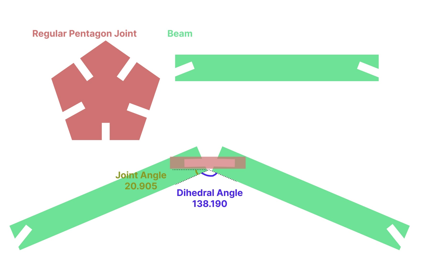
According to Wikipedia, the dihedral angle of a regular icosahedron is 138.190°. Therefore, the joint on the beam should be put at an accute angle of 20.905° ((180° - 138.190°) / 2) (turned out I'm terribly wrong).
Sketching it out in CAD
Watching Tutorials
My tool of choice is Fusion 360, and I don't have much experience with CAD software. I've watched a few tutorials to learn the basics.
- How to create a component & sketch
- How to use constraints
- Also how to use constraints
- How to export a specific sketch to DXF
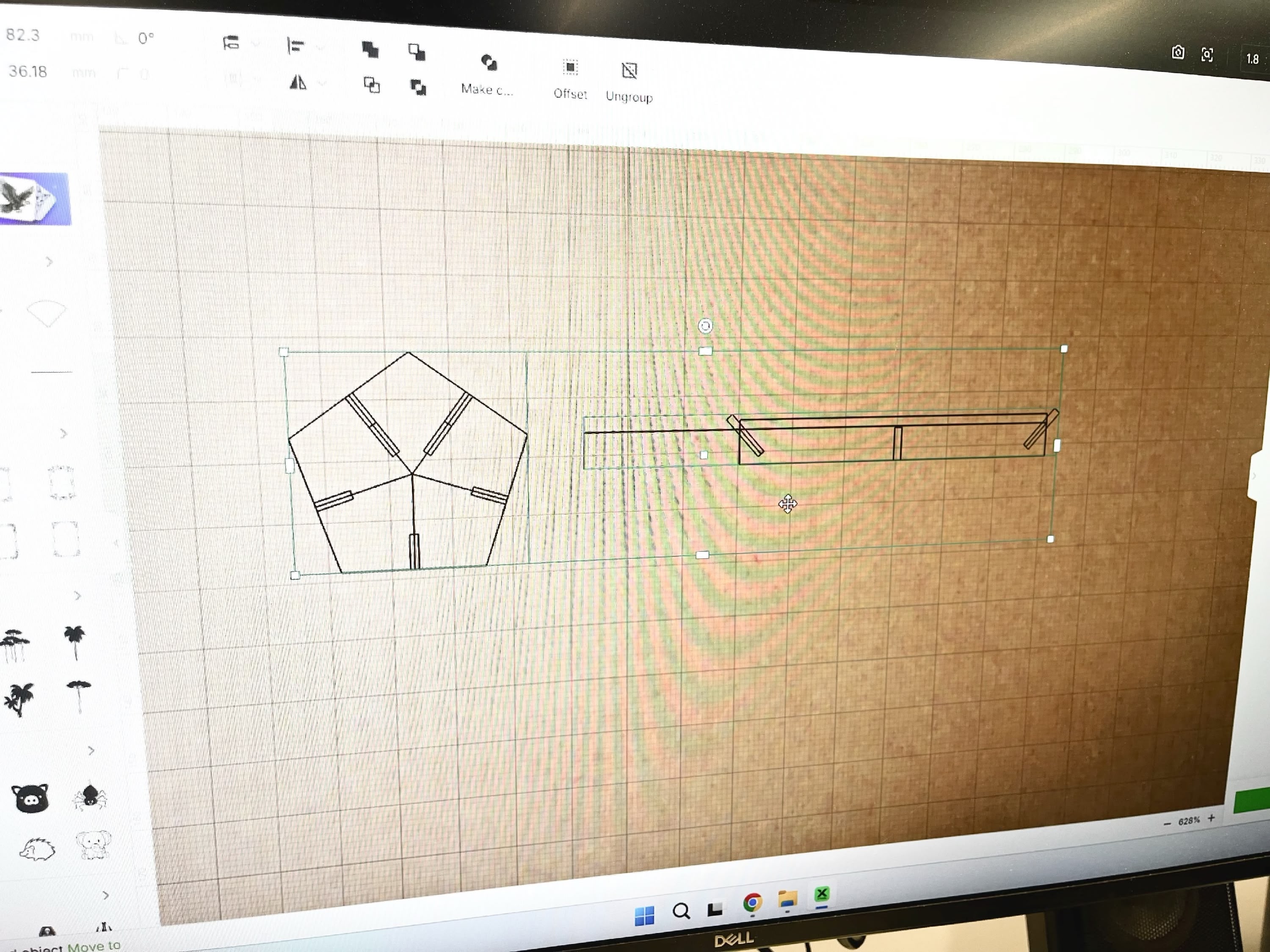
Sketching the Joint
I started by creating a component. I named it "ico_joint" and created a sketch on the component. We know In the first draft, I know that the joint should be a regular pentagon, so I created a regular pentagon, and attached a notch on each side, which are the joints that connects the cardboards.
As you can see, in this first draft, I already parameterized all the dimensions. Here's the table of parameters (exact values subject to change later):
Parameter | Value |
|---|---|
cardboard_joint_width | 4 mm |
ico_joint_radius | 20 mm |
cardboard_joint_length | 6 mm |
cardboard_joint_miter_radius | 2 mm |
cardboard_thickness | 10 mm |
A few notes for this data:
- The data is done before I characterized the laser cutter and cardboard, so the
cardboard_joint_widthandcardboard_thicknessare placeholder values. - I didn't know "Chamfer" is an estabilished operation in Fusion 360 for 3D body, so I manually implemented the rounded corner around the notch, controlled by
cardboard_joint_miter_radius. The arcs in these corners are later turned into "Construction Lines", and didn't affect the final geometry.
Sketching the Beam
I created a new component called "ico_beam" and created a sketch on the component. It's just a rectangle with an angled notch on each side.

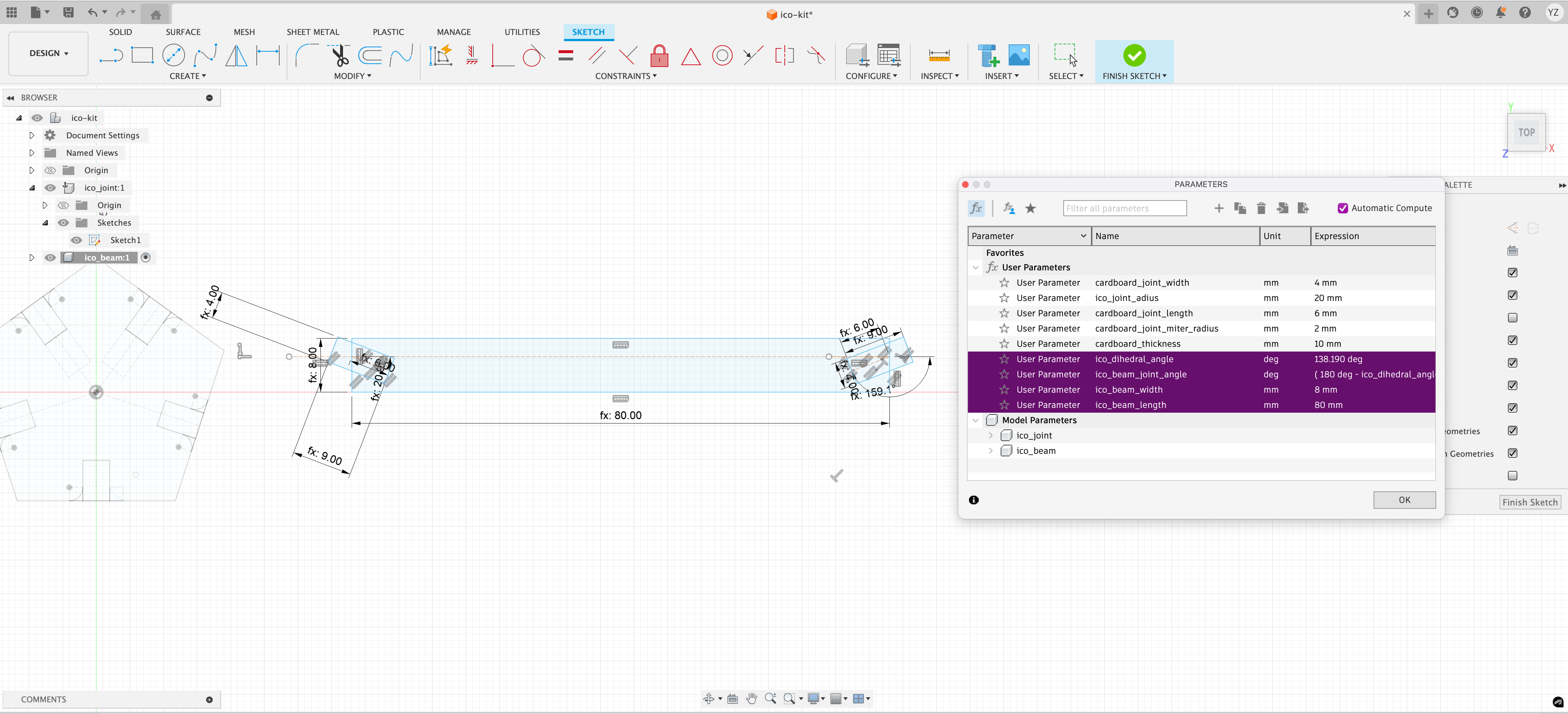
I added four more parameters to the sketch:
Parameter | Value |
|---|---|
ico_dihedral_angle | 138.190° |
ico_beam_joint_angle | (180 - ico_dihedral_angle) * 0.5 (~20.905°) |
ico_beam_width | 8 mm |
ico_beam_length | 80 mm |
A few notes for this data:
- Again, the
ico_beam_joint_angleis terribly wrong. I'll come back to this later.
Tweaking the Parameters
At this point, I've finished the characterization process, so I changed the parameters to the actual values.
Parameter | Value |
|---|---|
cardboard_joint_width | 1.4 mm |
cardboard_thickness | 1.8 mm |
Also, I took a second look at my icosahedron prototype and realized that the "Joint Angle" doesn't look like 20.905° just by eyeballing it.
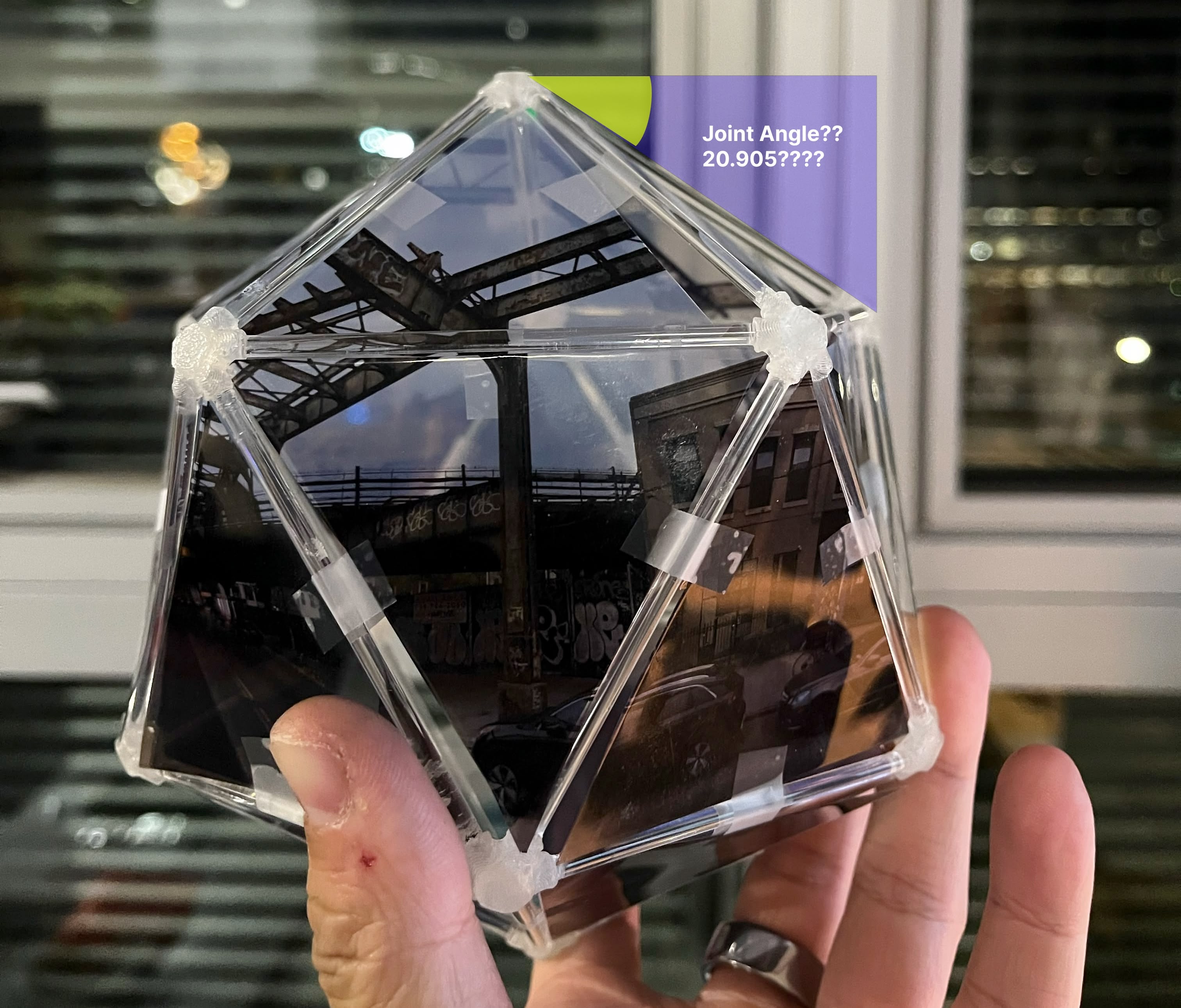
I convinced myself that this angle can definitely be derived from the "Dihedral Angle", which is 138.190°, and there for, instead of using (180-ico_dihedral_angle)/2, I'll use (180-ico_dihedral_angle), which is 41.81°. (This turned out to be another mistake...) Therefore, I changed the parameter to ico_beam_joint_angle to 41.81°.
Parameter | Value |
|---|---|
ico_dihedral_angle | 138.190° |
ico_beam_joint_angle | 180° - ico_dihedral_angle (~41.81°) |
From 2D to 3D
Thanks to parametric design, the geometry will be updated automatically. I now have two updated 2D sketches, and I'm extruding them into 3D bodies (by the thickness of cardboard_thickness).
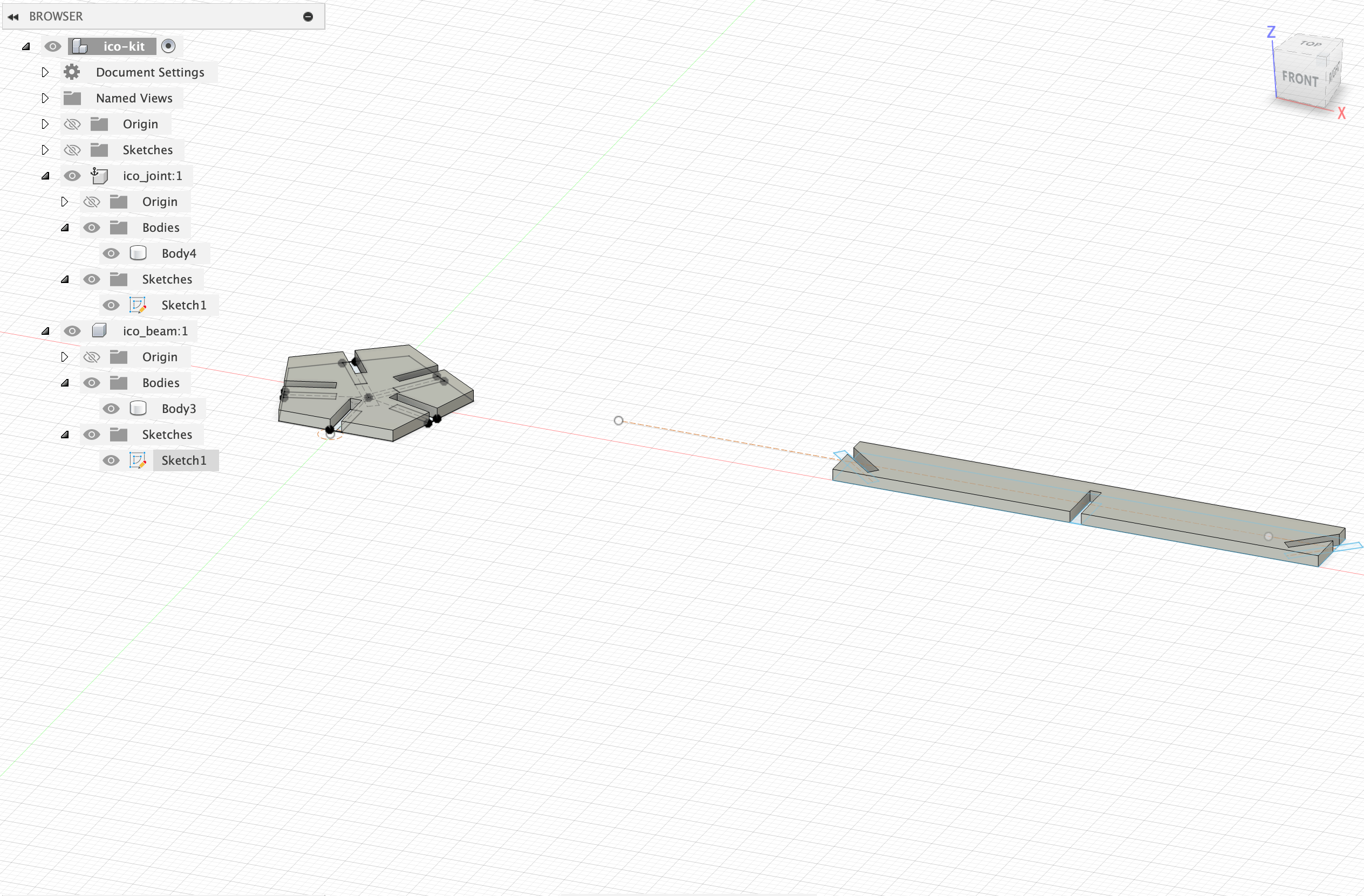
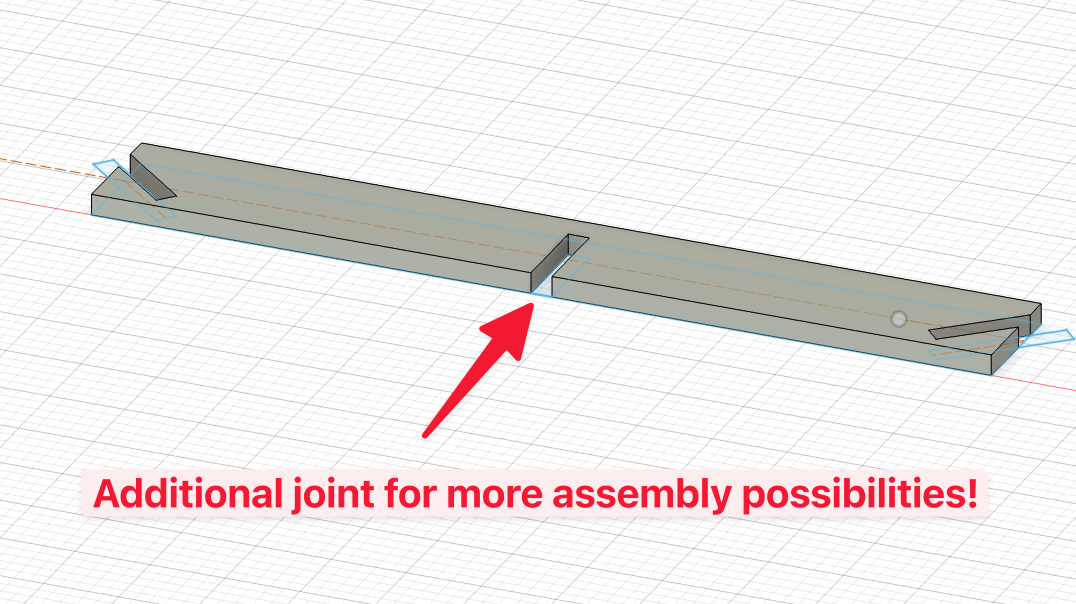
Note that I added an additinal notch in the middle of the beam to add more flexibility to the assembly. Since the prompt for the assignment requires "assembled in multiple ways", on top of the fixed icosahedron assembly, I want to be cable to stack icosahedrons on top of each other. (Spoiler: The extra notch turned out to be useless and a miscalculation.)
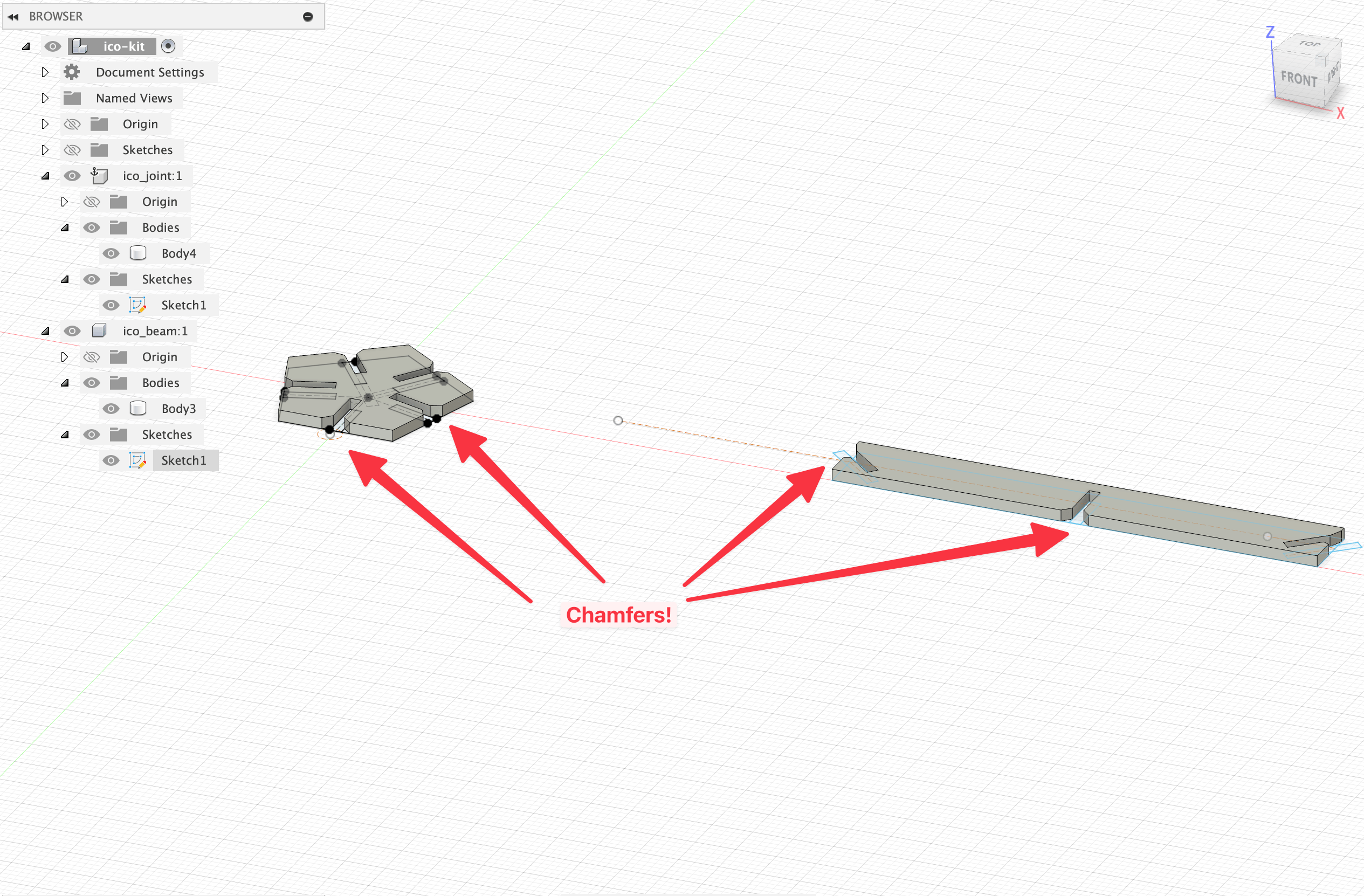
Chamfering the Edges
I figured out that in the "Modify" tab, I can "Chamfer" the edges around the notch. I chamfer the edges around the notch with new parameter chamfer (currently set to 1mm).
Exporting the DXF files
I remember I need to export my design to DXF files for laser cutting. What I tried first is to go for DXF export in "File" > "Export" > "DXF".
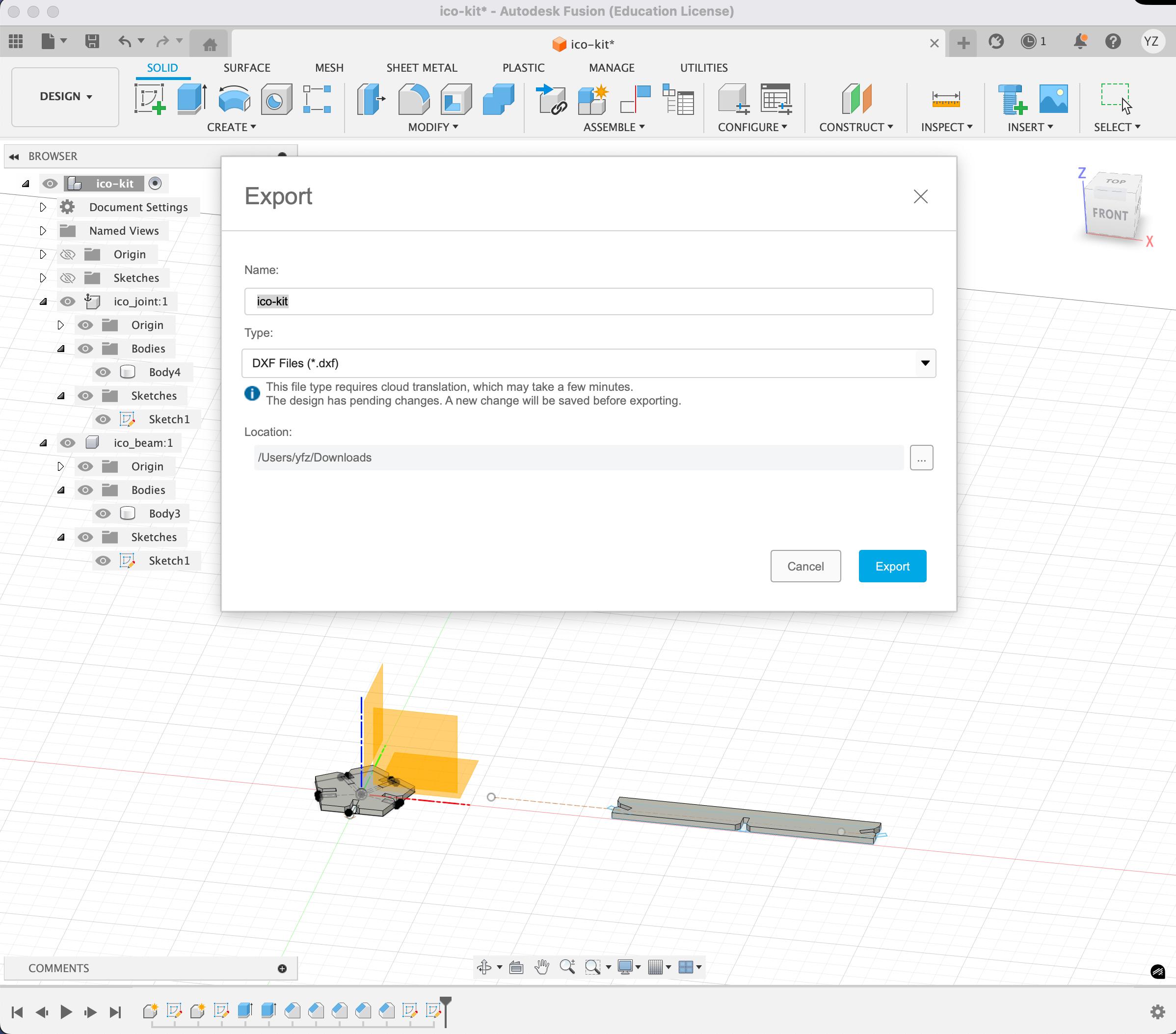
Bringing it to the xTool software, I noticed that the DXF file contains all the unnecessary construction lines from my sketches, and none of the chamfered edges (which is a 3D geometry operation).
Upon some investigation, I realized DXF is exclusively for 2D sketches. There's no magic that converts your 3D geometry to 2D at export time. To export properly, I need to do the following:
- Create two new 2D sketches, one for the joint and one for the beam
- In skecth mode, project (shortcut:
P) the chamfered geometry bodies to 2D on each sketch - Export the two sketches as DXF files by right clicking on the sketch and selecting "Export" > "DXF"
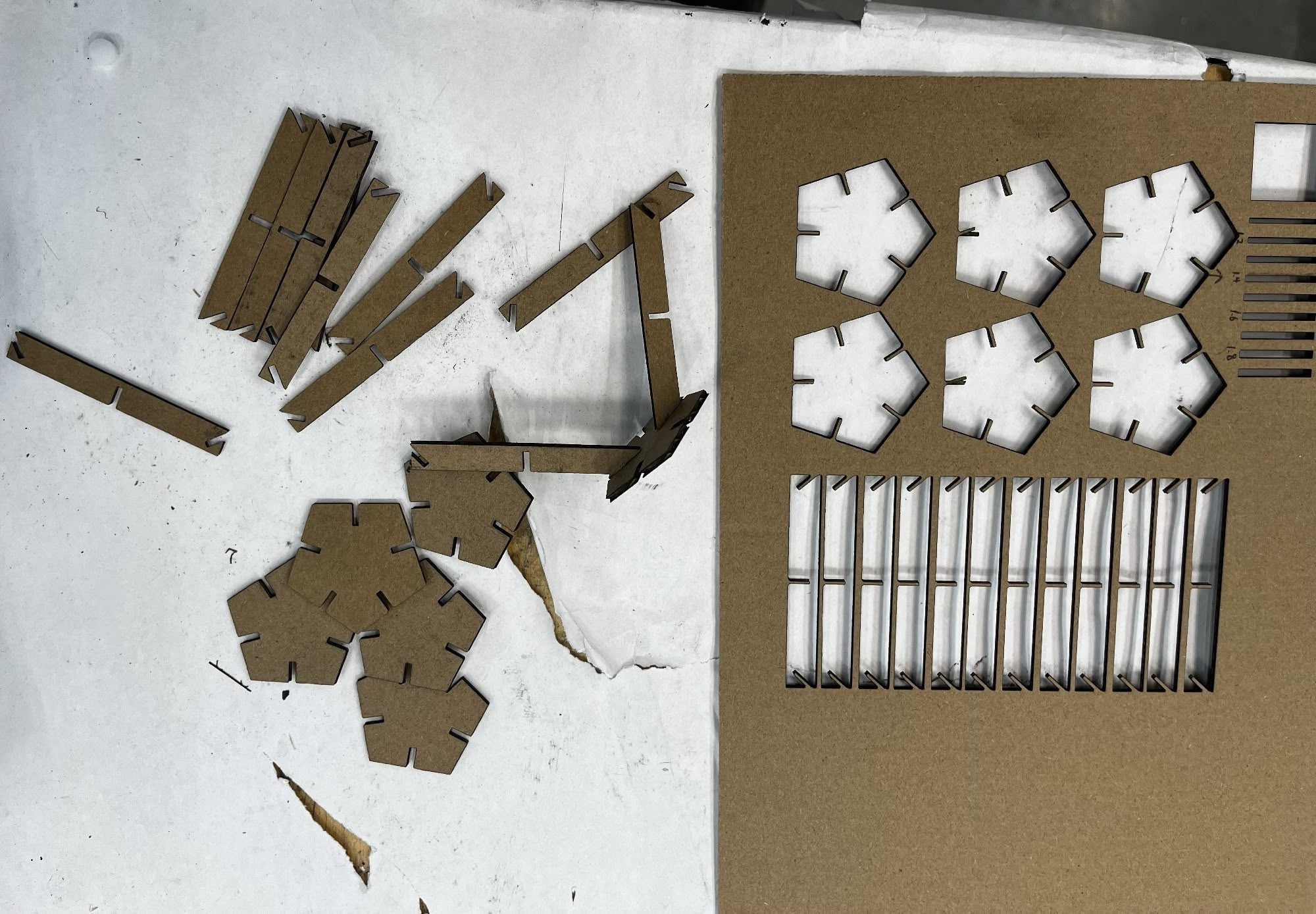
The First Cut
I brought the two DXF files to the xTool software and cut them. I first cut out 6 pentagon joints, and 12 rectangle beams.
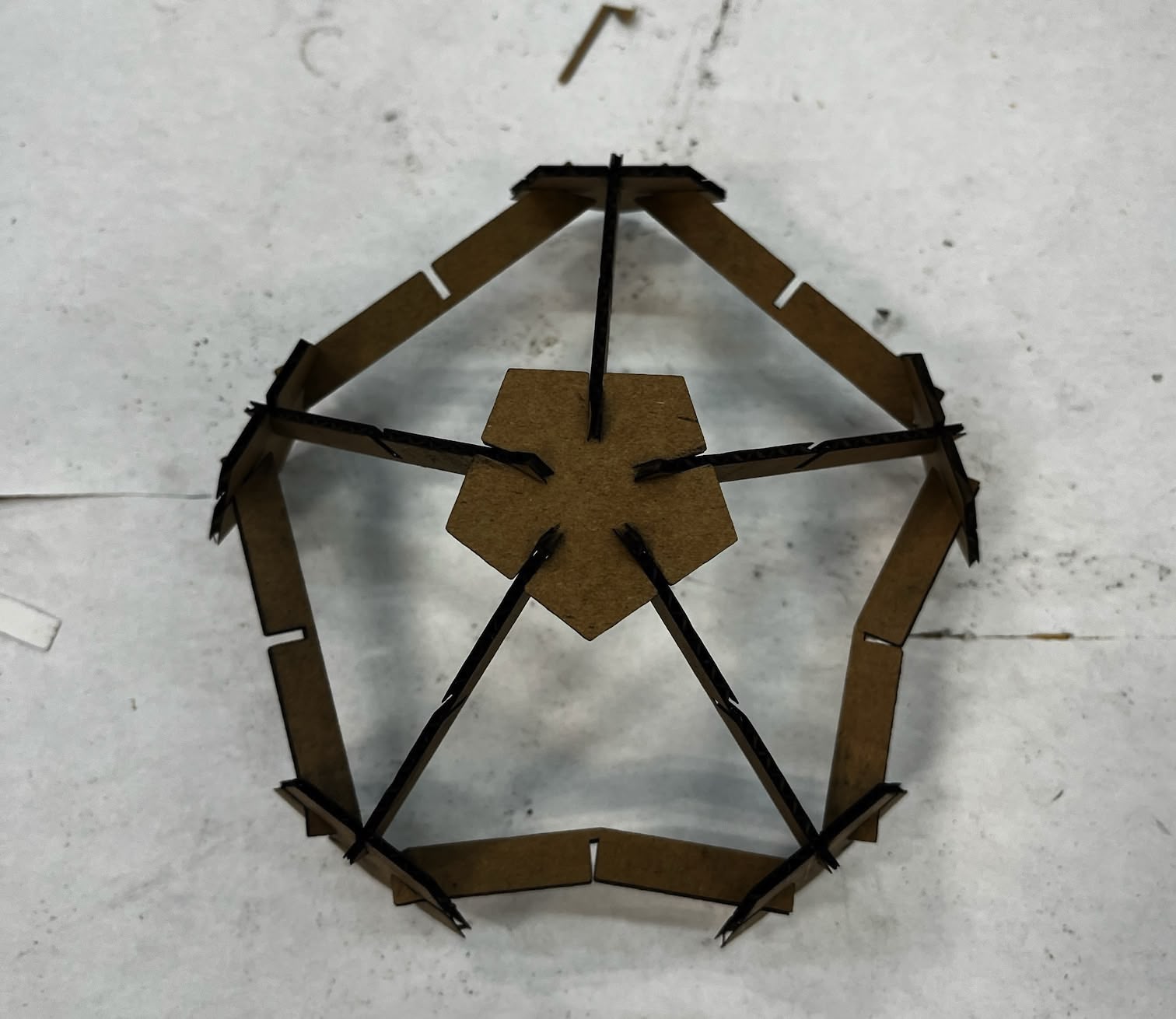
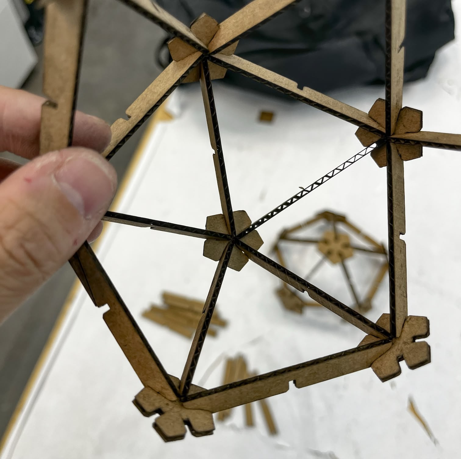
Unfortunately, I soon realized 41.81° is not the correct angle. It turns out the beam is too long to even assemble a single equilateral triangle face, which means the "Joint Angle" is probably too big. The correct angle is smaller than 41.81°.
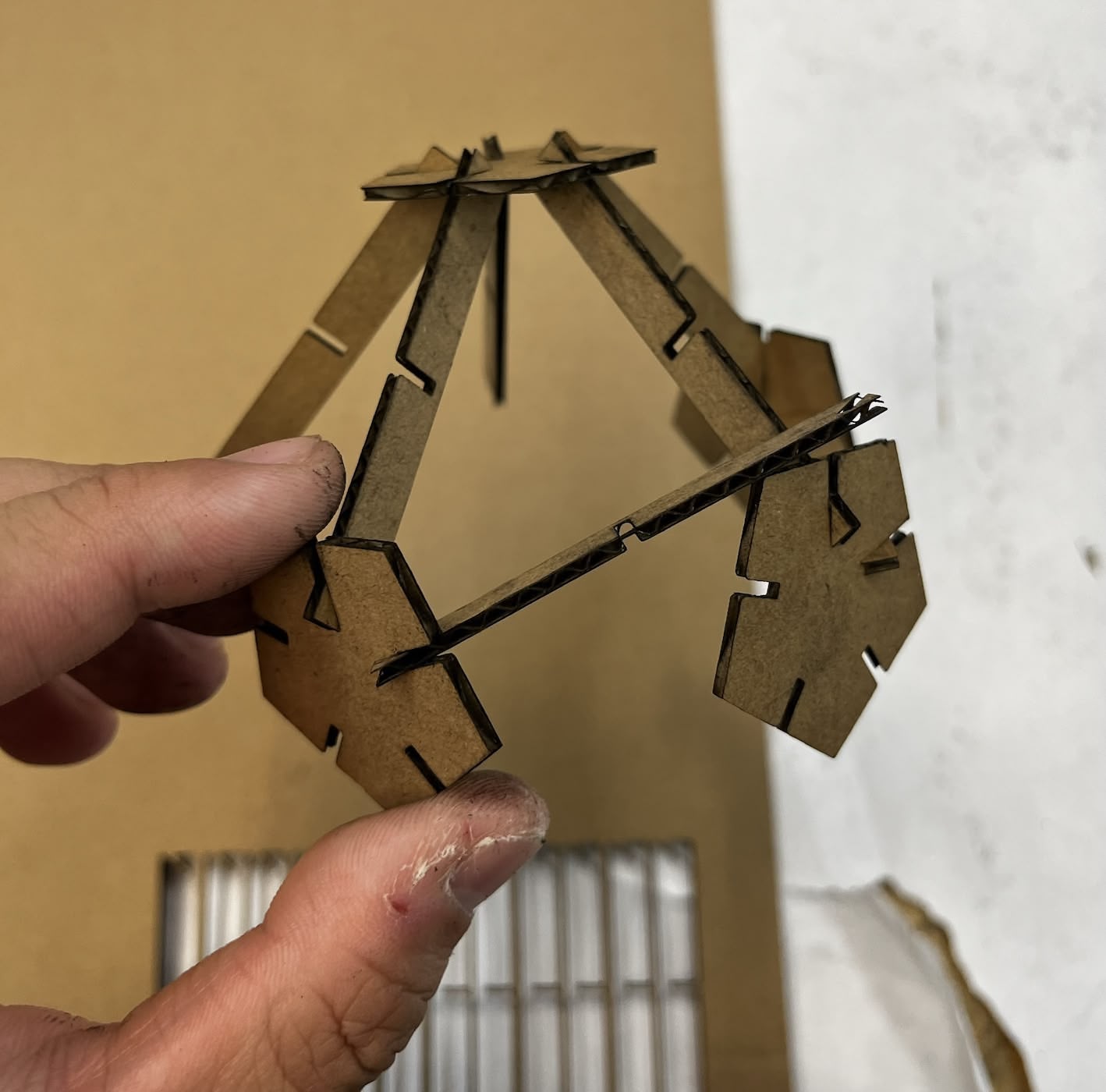
I tried to force the beam to fit, but then the beams would bend too much. This is also caused by the middle notch being too long, leaving the beam having too little support.
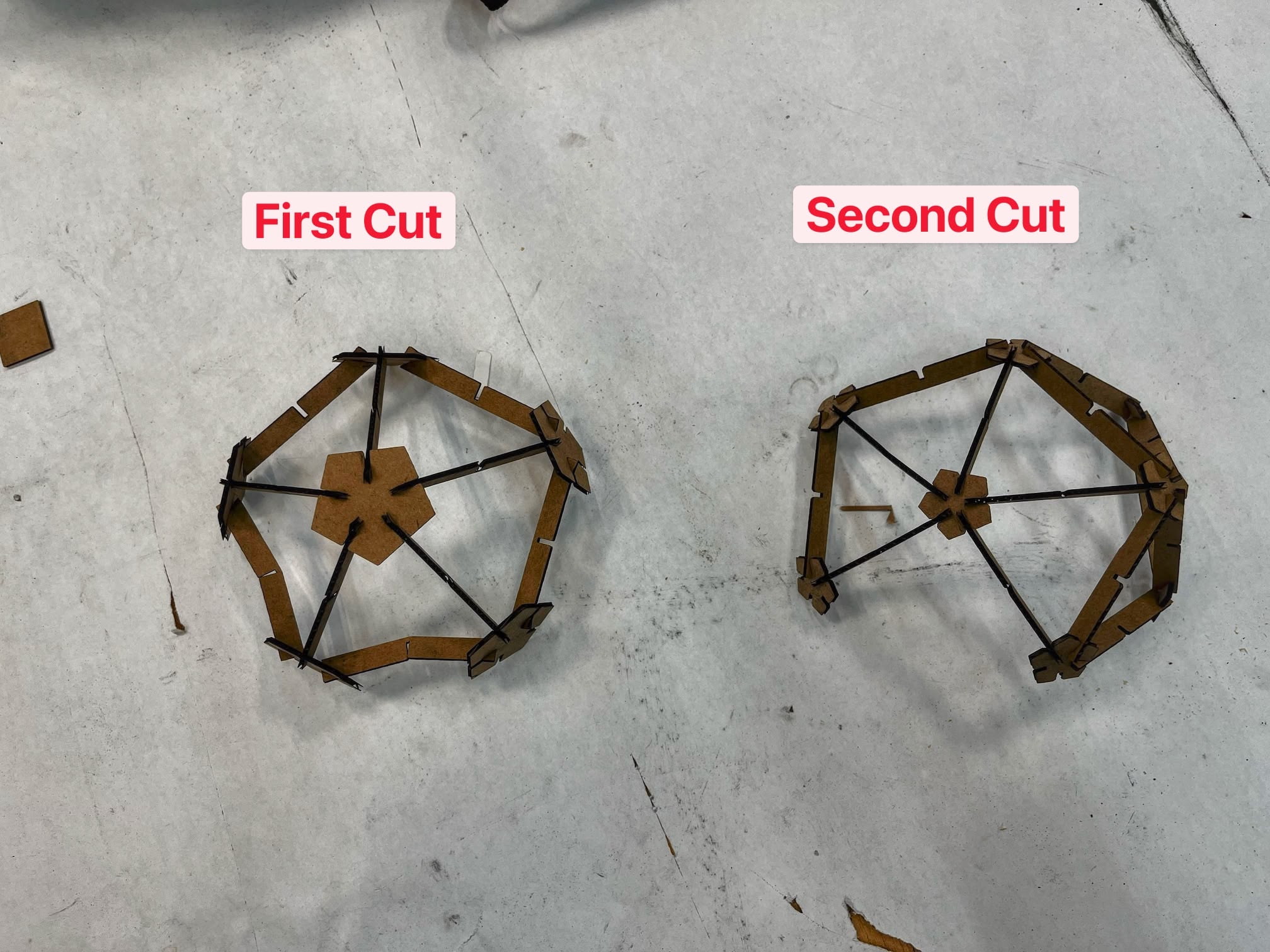
The Second Cut
Still convinced that the "Joint Angle" is easily derived from the "Dihedral Angle", I went back to the CAD software and changed the "Joint Angle" back to 20.905°. The second iteration also features a smaller pentagon joint and smaller joint length. Here's the table of parameters:
Parameter | Value | Note |
|---|---|---|
ico_joint_radius | 12 mm | Smaller pentagon |
cardboard_joint_width | 1.4 mm | |
cardboard_joint_length | 4 mm | Shorter joint /notch |
cardboard_thickness | 1.8 mm | |
ico_dihedral_angle | 138.190° | |
ico_beam_joint_angle | 180° - ico_dihedral_angle (20.905°) | Back to where we started |
ico_beam_width | 8 mm | |
ico_beam_length | 60 mm | Shorter beam |
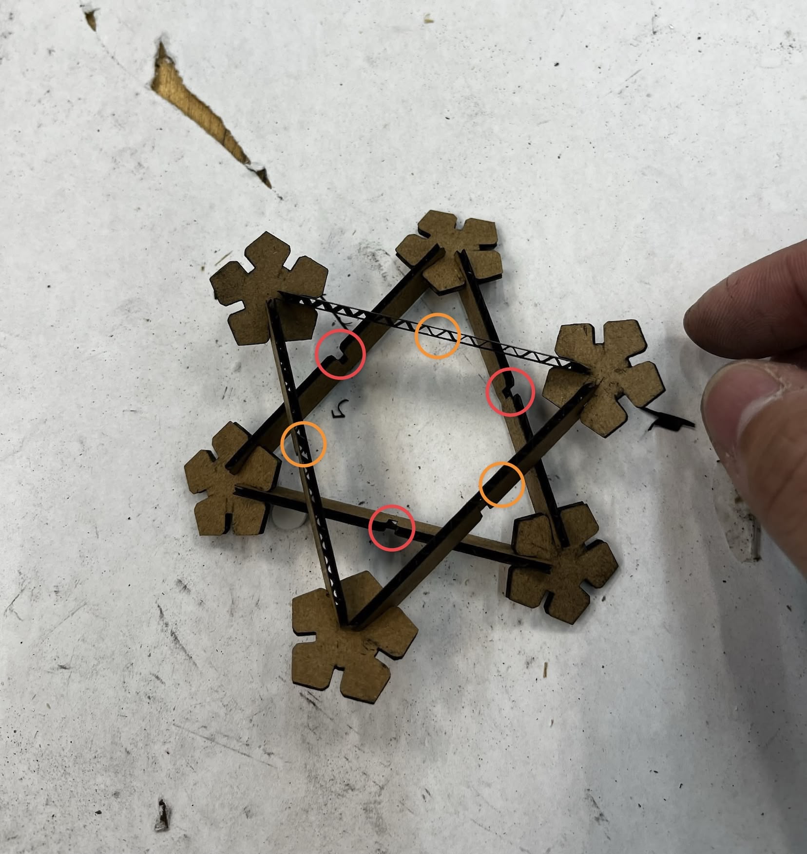
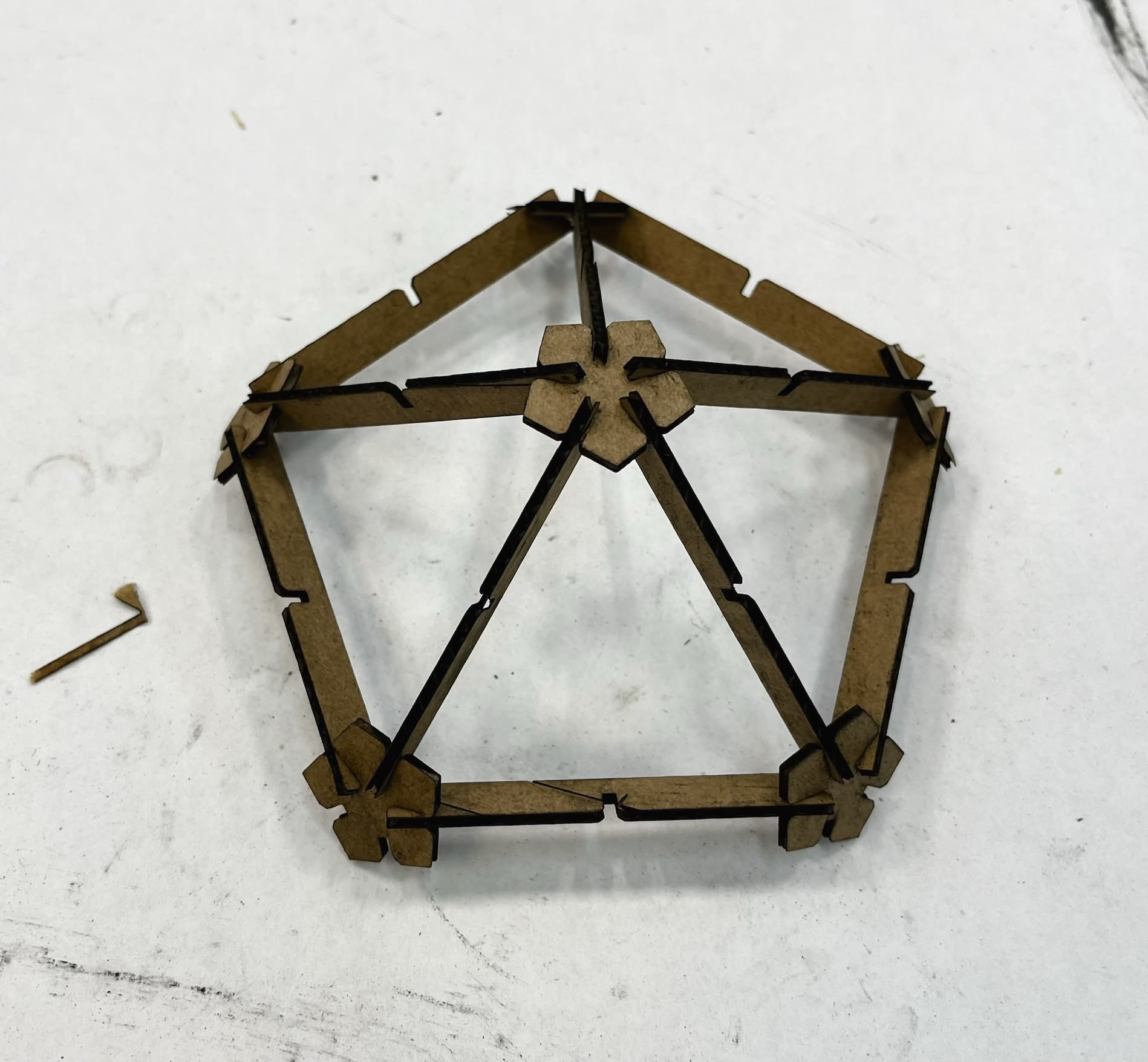
The second cut turned out better, but 20.905° is still not the correct angle... It seems to be too small, which means the beam fails to reach the joint at certain triangles.
By that time, I also realized that the middle notch doesn't allow the shape to stack the way I wanted it to. I really should have tried to aseemble the piece in the CAD software first.
The Final Cut
Three times the charm!
At this point, I'm pretty sure that it's just the "Joint Angle" that's wrong. I've not done enought trigonometry in 3D so I decided to cheat by just pure measurement. I found an image of a side projection of a regular icosahedron from a math website.
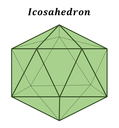
Shamefully, I imported the image into Figma and measured the angle by holding a rotated rectangle next to the edge. The rotation of the rectangle is 26.67°, which is the "Joint Angle" I need.
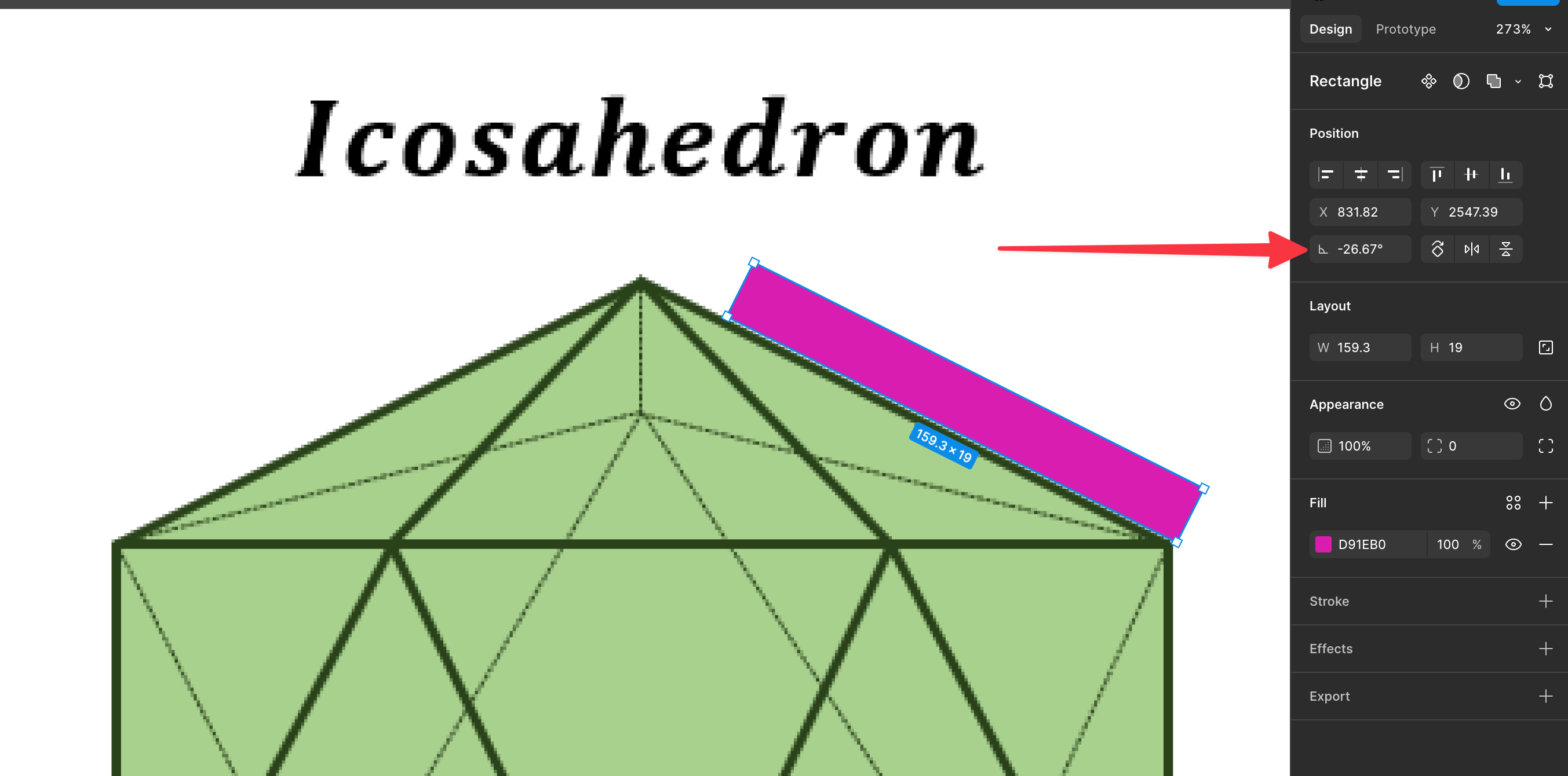
Once again, I went back to the CAD software and changed the ico_beam_joint_angle to 26.67°, and cut the third iteration. This time, it fits much better!
Thanks to the more compact pentagon joint, the beam fits tightly at the inner side of the joint.
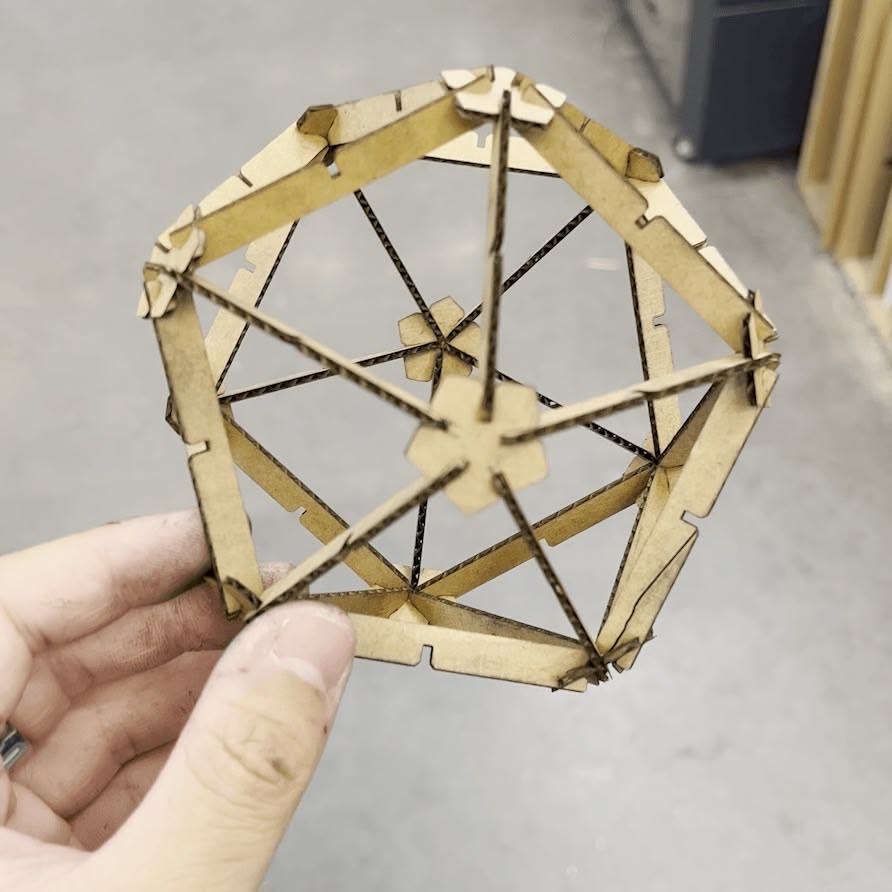
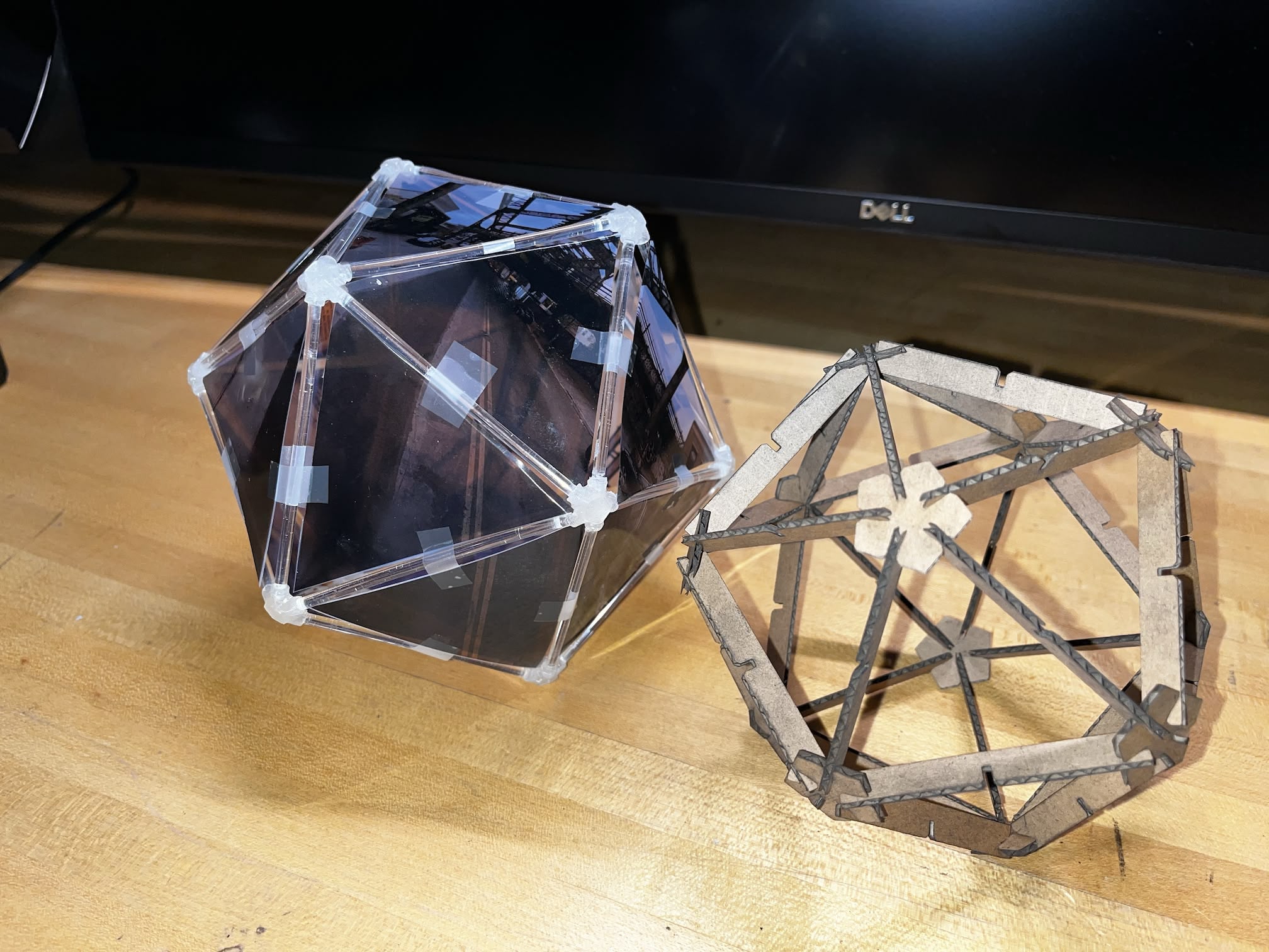
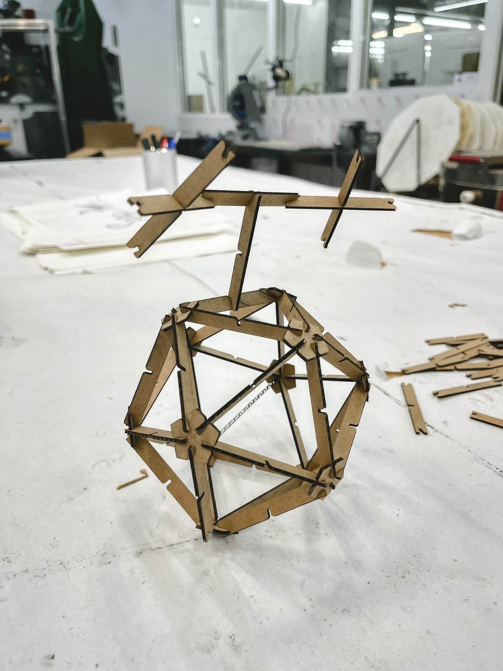
Here's the fully assembled icosahedron with 30 beams (edges) and 12 joints (vertices), side by side with my original lightbox prototype.
Here's the leftover cardboard with all the holes.
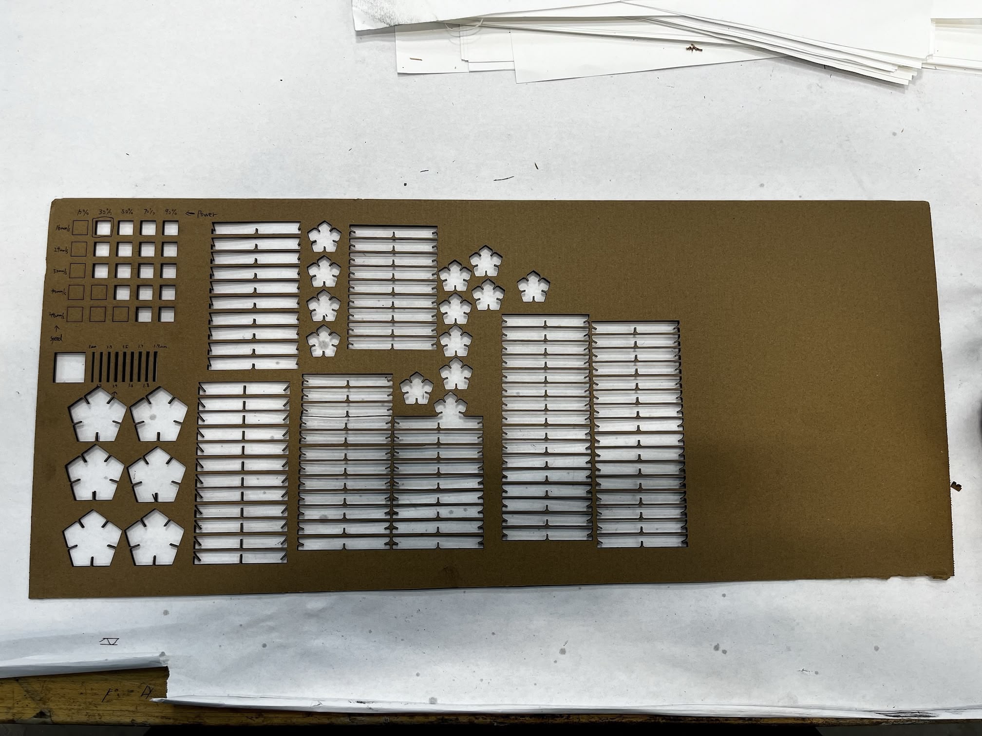
The hole size is 1.4mm, which is the same as the "Joint Width" I used in the CAD design.
I also performed a drop test to see if the kit is sturdy. It survived the first drop, but the second drop broke a few joints...
In terms of "assembled in multiple ways", although I couldn't stack the faces nicely on top of each other, but the middle notch allows me to assemble the spare beams in some interesting ways. I guess this would suffice for the assignment (please...).
References
- xTool Kerf Offset Function Description
- Regular Icosahedron
- Icosahedron Printed Joints Generator
- Day 1 of Learn Fusion 360 in 30 Days for Complete Beginners! - 2023 EDITION
- Midpoint Constraint Top Tips in Autodesk Fusion 360
- Sketches in Autodesk Fusion 360 - Ultimate Guide
- 4 Ways to Export to DXF in Fusion 360
- Icosahedron from helpingwithmath.com