Assignment
- demonstrate and compare the toolchains and development workflows for available embedded architectures
- browse through the data sheet for a microcontroller
- write and test a program for an embedded system using a microcontroller to interact (with local input &/or output devices) and communicate (with remote wired or wireless connections)
- extra credit: try different languages &/or development environments
The Board
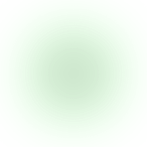
The board I got from the TAs (thanks to Alan and Quentin for helping during late hours!) is the Seeed Studio XIAO RP2040. It already came soldered with a USB-C port, a 128x64 OLED display, and onto a PCB board (QPAD) with 6 contact pads into the board.
Setting up Toolchain environment
The only info I have about the board is that it says "Seeed XIAO RP2040" on the board. I googled around and found [the datasheet]](https://files.seeedstudio.com/wiki/XIAO-RP2040/res/rp2040_datasheet.pdf) on SeeedStudio's website.
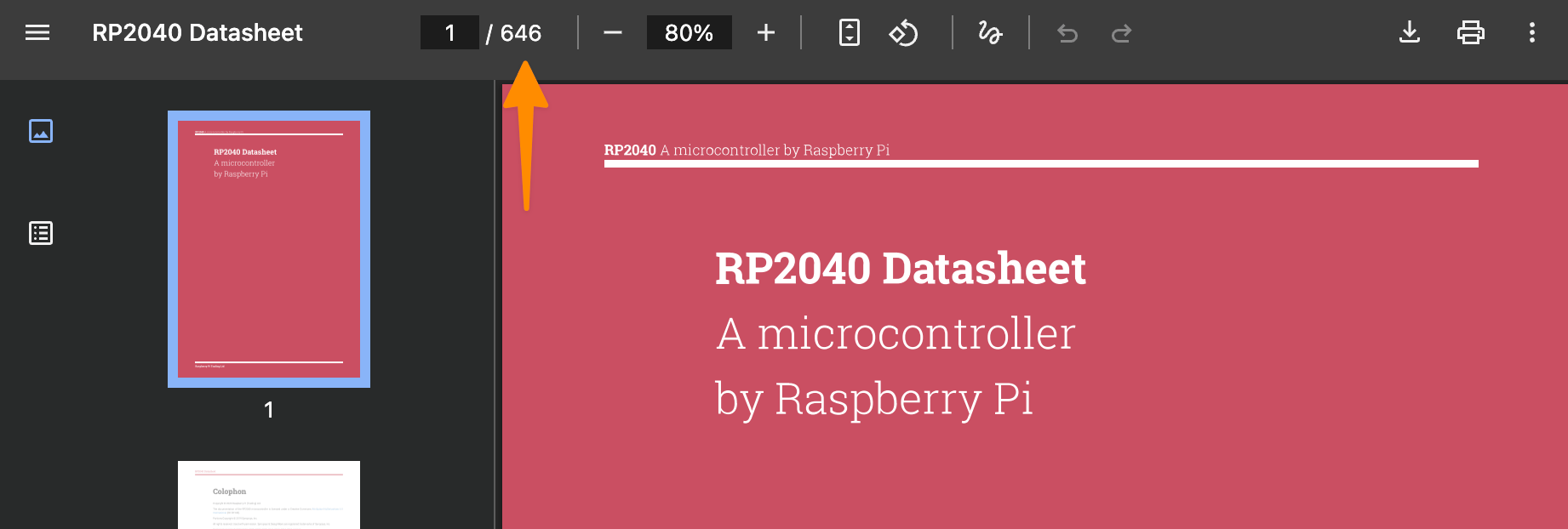
It's a 646 pages long PDF and I probably don't need to read it all. The second best resource I found is this guide published by Marcelo Rovai.
Setting up Arduino IDE
In the first chapter of the guide, it mentions how to set up the Arduino IDE to program the board. First, I need to add this URL as an "Additional Boards Manager URLs" in the Arduino IDE.
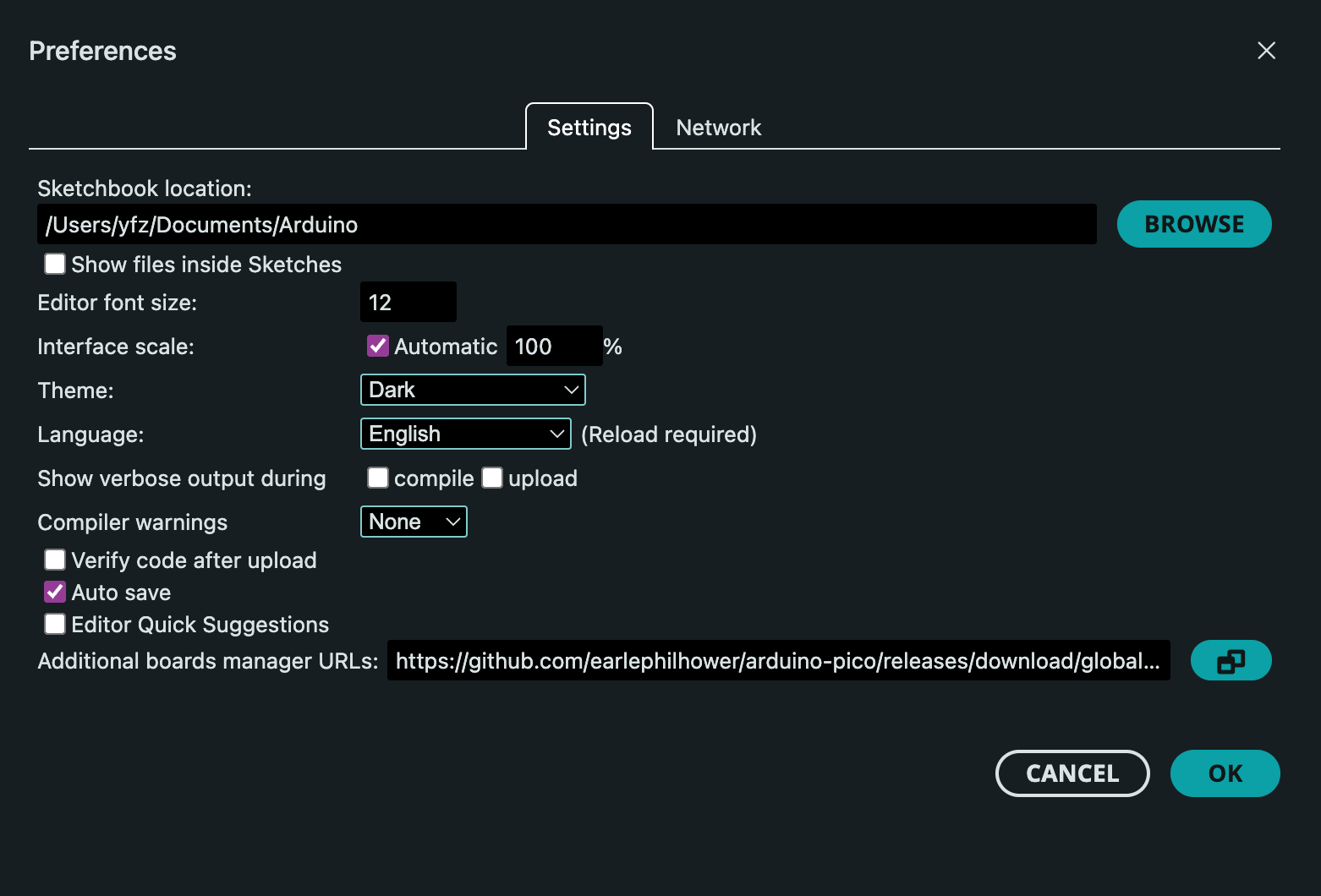
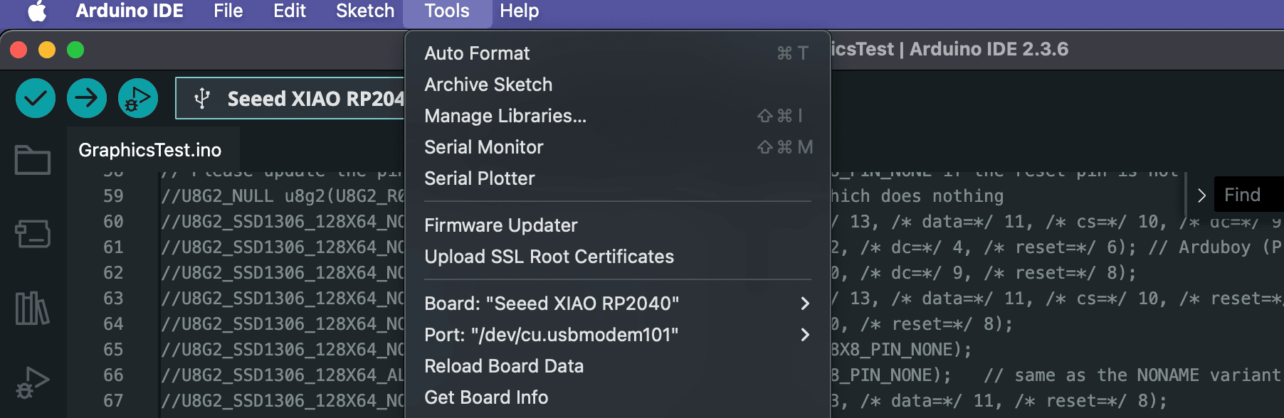
Then, when I open the "Tools > Board > Boards Manager", I can see the "RP2040 Boards" in the list, and clicked "Install". After that, the board module is available in the "Tools > Board" menu. After setting the port to the correct one, I think I'm ready to start programming the board.
Setting up VS Code + PlatformIO
I've heard good things about VS Code + PlatformIO, which allows me to stay in the familiar VSCode ecosystem and leverage some of the AI capabilities. I found a good guide on how to set it up from PlatformIO's website for specidically RP2040.
After I installed PlatformIO on VS Code, the following steps are setting up the project files. According to the guide, it seems like I needed a platformio.ini file to tell PlatformIO what to do. The guide is not showing the exactly RP2040 setup, so I consulted Claude Sonnet 4 (Reasoning) with the prompt.
help me setup a platform io project in vscode for Seeed XIAO RP2040
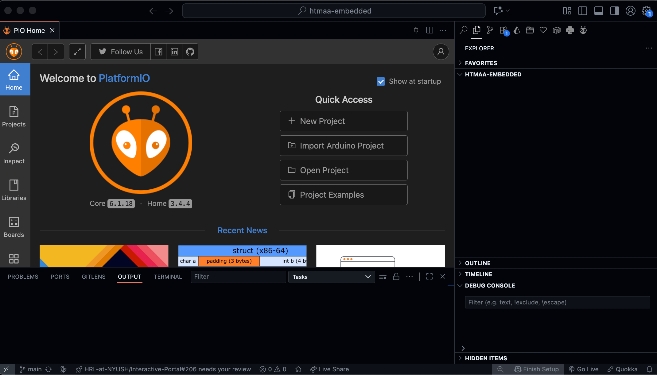
It advised me to "Open PlatformIO Home" (search in the command palette by pressing Ctrl/Cmd+Shift+P) and click "New Project".
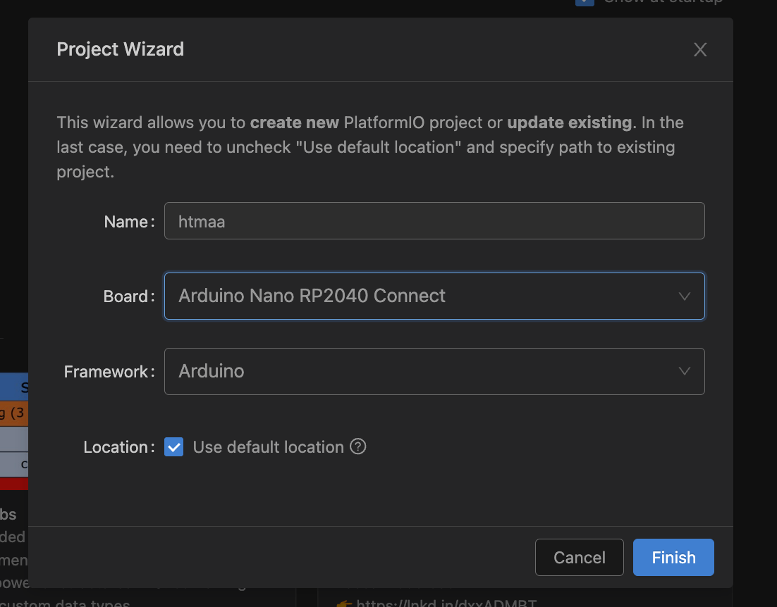
For the board type, I tried to find "RP2040" in the list, and the closest thing I found is "Arduino Nano RP2040 Connect". The more Seeed XIAO related options only has SAMD and ESP32 options.
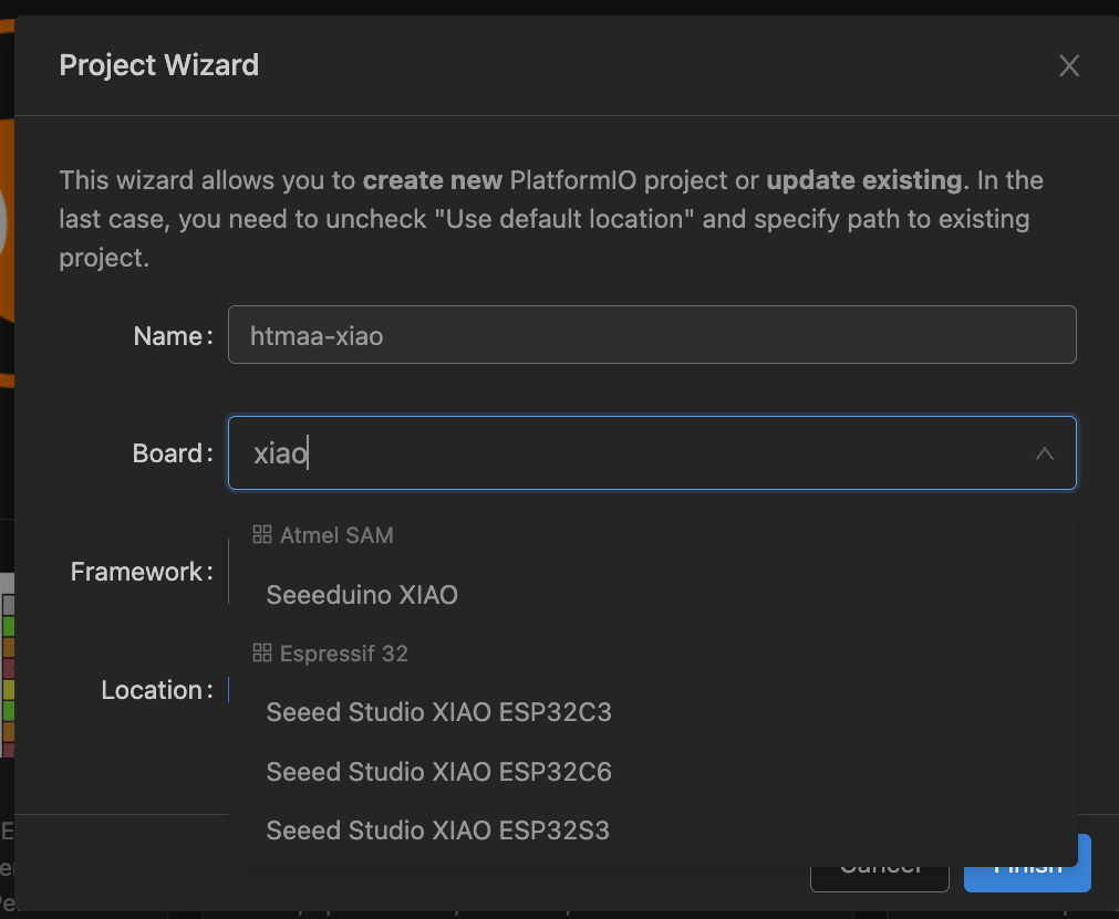
After initializing the project, I can see the platformio.ini file is created. Right off the bat, I went straight to trying to upload the default empty program to the board. Not too surprisingly, it failed, because essentially my board (Seeed XIAO RP2040) is not on the list of supported boards.
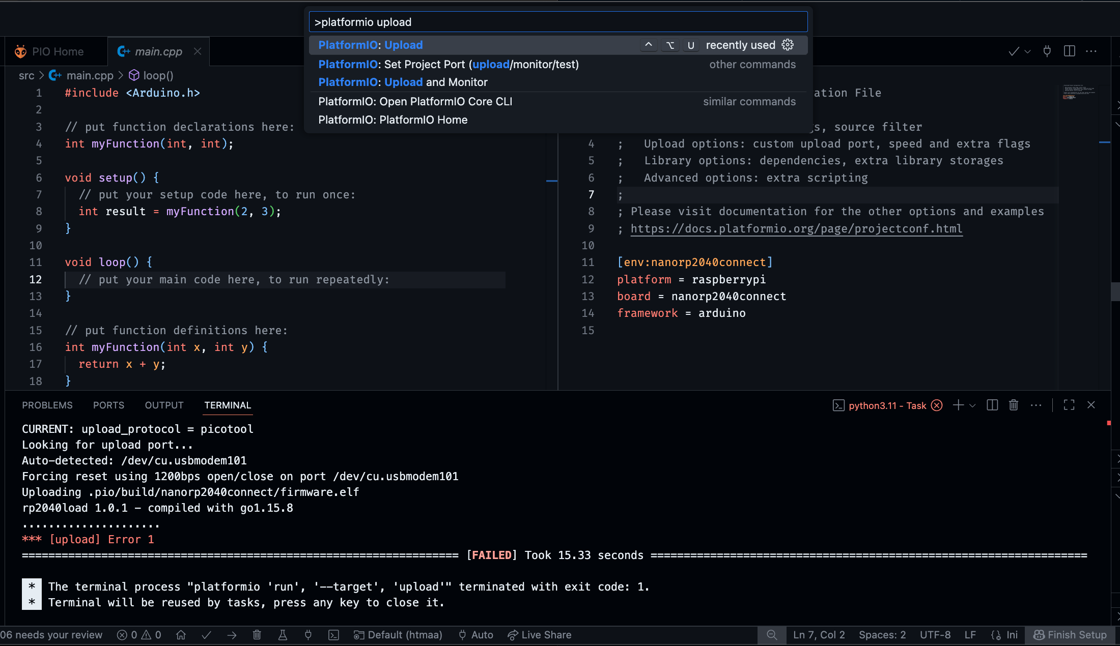
Given this, I decided to go forward with the Arduino IDE, and set up the board as described in the previous section.
Testing the OLED Display
For most of my initial exploration, I completely missed out the examples that Quentin provided. I saw the GitLab repo and the website, but I didn't pay attention to the code folder.
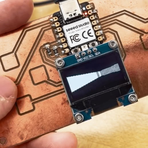
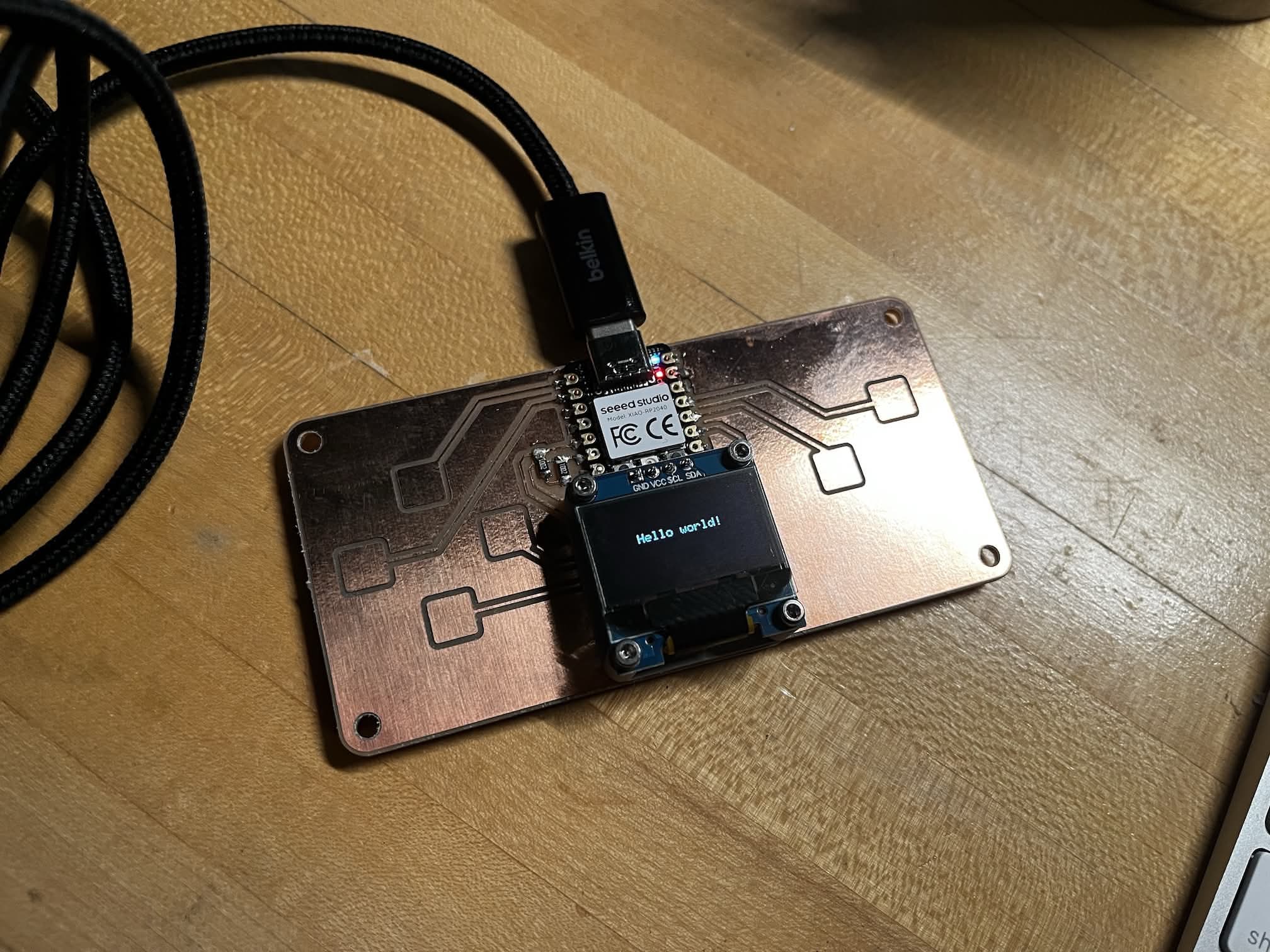
Following Chapter 1.6 of the guide by Marcelo Rovai, I was able to get the board to display "Hello" on the OLED display. I downloaded and installed the U8g2 library, and flashed on of the exmaples, named GraphicsTest.ino. The only thing I have to modify in this example is to set the U8X8 declaration by uncommenting the following line (as stated in the guide):
U8X8_SSD1306_128X64_NONAME_HW_I2C u8x8(/* reset=*/ U8X8_PIN_NONE);
Testing the Touch Pads
This was the most confusing part. Without Quentin's examples, I went on researching how to implement capacitive touch sensing on RP2040. Because according to the pin definition, the 6 QPAD touch pads are connected to the P1, P2, P3, P4, P26, and P27 pins.
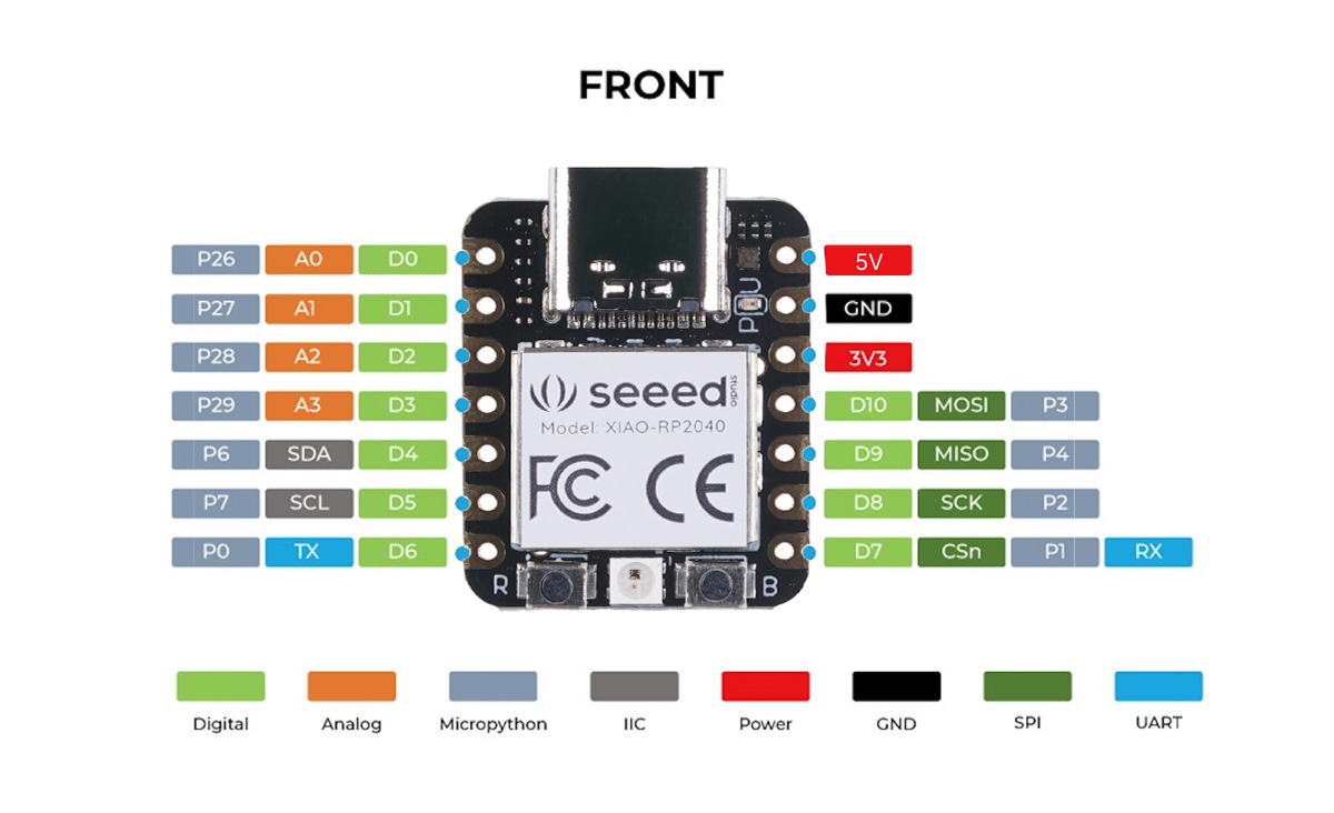
I was very confused how to utilize these pins to detect touch events, since, unlike SAMD, the RP2040 does not have a built-in Peripheral Touch Controller (PTC). I was looking around for random libararies, such as the Adafruit_FreeTouch, CapacitiveSensor libraries, but none worked.
In the end, I successfully bricked my board by flashing one of the randome sketches I co-conspired with ChatGPT. The board wouldn't show up in the port list in the Arduino IDE. I tried to follow this guide on Seeed Studio's website to reset the board by reconnecting the cable while pressing the reset button. It didn't work either.
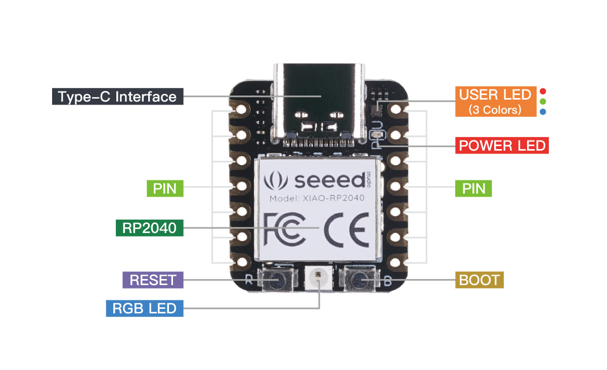
After countless failed attempts, I reached out to Quentin for help. He told me to properly reset this exact board, the correct steps are:
- Plug in the board
- Keep the BOOT button pressed
- Press and release the reset button
The board then goes to UF2 mode, where it shows up as a USB storage device.
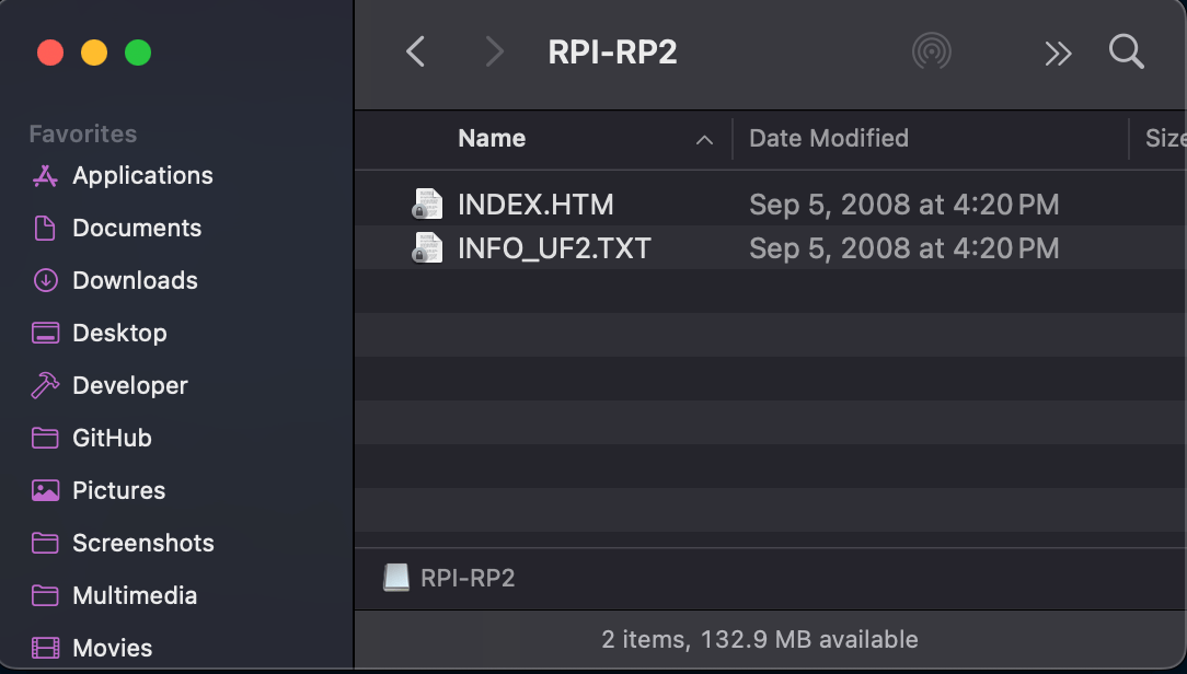
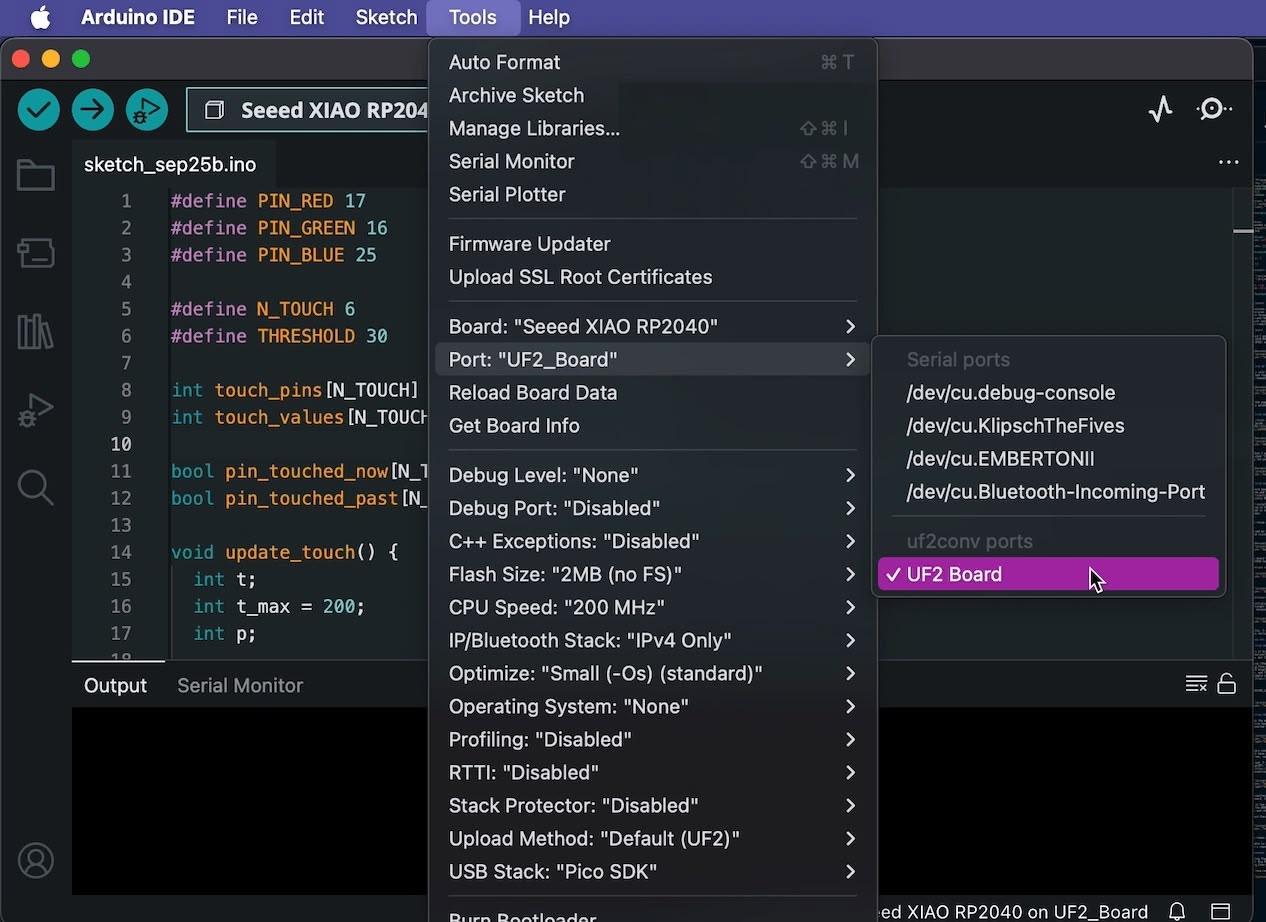
It also shows up in the "Port" menu in the Arduino IDE, as a "UF2 Board".
Then, I copied over Quentin's test_touch_RP2040.ino example to the board. It successfully flashed, however, the board wouldn't respond to the touch events.
After some debugging with Quentin, we decided to remove these two lines to make it work:
noInterrupts();
// some other code
interrupts();
Back to the example touchpad code itself, Quentin obviously performed some neat tricks to make RP2040, with no PTC, to detect touch events.
At earch cycle, first we reset all the pins to LOW. After some delay to make the voltage settle, we enable INPUT_PULLUP on the pins, to allow the pins to slowly charge up. Then, we set the pins to HIGH for a short period of time, to detect the capacitance of the pins. After that, we will be measuring the time it takes for the pins to charge up. It takes too long to charge up, it means that something is touching the pins, probably a finger.
// from test_touch_RP2040.ino
void update_touch() {
  int t;
  int t_max = 200;
  int p;

  for (int i = 0; i < N_TOUCH; i++) {
    p = touch_pins[i];

    // set to low
    pinMode(p, OUTPUT);
    digitalWriteFast(p, LOW);

    // settle
    delayMicroseconds(25);

    // make sure nothing else interrupts this
    //noInterrupts();

    // enable pull-up
    pinMode(p, INPUT_PULLUP);

    // measure time to rise
    t = 0;
    while (!digitalReadFast(p) && t < t_max) {
      t++;
    }
    touch_values[i] = t;

    // re-enable interrups
    //interrupts();

    // update state
    pin_touched_past[i] = pin_touched_now[i];
    pin_touched_now[i] = touch_values[i] > THRESHOLD;
  }
}
This explains why this particular example is hard to find online: because it's not a common use case for RP2040. It's also only possible for a relatively fast microcontroller, because the time it takes for the pins to charge up is relatively short, therefore hard to detect with a slow microcontroller.
Finally, the assignment
Initial Plan
I decided to implement a program to make the board a HID keyboard, which propogate the source code of the program itself, when the user press the START key. But it turns out to be a whole field of study called Quine - a program that reproduce its own source code. It's not very trivial to design such a program.
I found a few of them on a website. Here's a popular one I've seen in C are quite short and make use of the string literal feature.
main(){char*s="main(){char*s=%c%s%c;printf(s,34,s,34);}";printf(s,34,s,34);}
Alternative Plan
I decided to implement a movable raycasting engine like the one in Wolfenstein 3D. The player would be able to move around the map, and the walls would be rendered with a simple flat shading with a single light source. And I would implement some dithering because the OLED display is black and white.
I found a good Youtube tutorial on how to implement the Digital Differential Analyzer (DDA) algorithm for a more performant raycasting. An detailed article by Lode also provide a good explanation of the algorithm. Note that it only works for tile based map, which means the walls would be made of unit squares.
Implementation
I asked Claude Sonnet 4 (Reasoning) to digest Quentin's two examples (with input and display) and draft a code skeleton for the raycasting engine. I specifically said "All imperative and no OOP, keep it simple, and struct is ok". It turns out it did too much for me by implementing a full-fledged raycasting logic. So I deleted the raycasting functions and reimplemented myself. Here's the core stuff:
int worldMap[MAP_WIDTH][MAP_HEIGHT] = {
  {1,1,1,1,1,1,1,1,1,1},
  {1,0,0,0,0,0,0,0,0,1},
  {1,0,0,0,0,0,0,0,0,0},
  {1,0,1,1,1,1,1,1,0,1},
  {1,0,0,1,0,0,1,0,0,1},
  {1,0,0,1,0,0,1,0,0,1},
  {1,0,0,0,0,0,0,0,0,1},
  {1,0,0,0,0,0,0,0,0,1},
  {1,0,0,0,0,0,0,0,0,1},
  {1,1,1,1,1,1,1,1,1,1}
};

// ... other code ...
struct RaycastHit {
    float distance;
    int side; // 0 = NS wall, 1 = EW wall
};


// Very nice raycasting functions
RaycastHit cast_ray(float startX, float startY, float rayDirX, float rayDirY) {
  int mapX = (int)startX;
  int mapY = (int)startY;

  float deltaDistX = abs(1.0f / rayDirX);
  float deltaDistY = abs(1.0f / rayDirY);

  int stepX, stepY;
  float sideDistX, sideDistY;

  if (rayDirX < 0) {
    stepX = -1;
    sideDistX = (startX - mapX) * deltaDistX;
  } else {
    stepX = 1;
    sideDistX = (mapX + 1.0f - startX) * deltaDistX;
  }

  if (rayDirY < 0) {
    stepY = -1;
    sideDistY = (startY - mapY) * deltaDistY;
  } else {
    stepY = 1;
    sideDistY = (mapY + 1.0f - startY) * deltaDistY;
  }

  // DDA
  int hit = 0;
  int side;

  while (hit == 0) {
    if (sideDistX < sideDistY) {
      sideDistX += deltaDistX;
      mapX += stepX;
      side = 0;
    } else {
      sideDistY += deltaDistY;
      mapY += stepY;
      side = 1;
    }

    if (is_wall(mapX, mapY)) hit = 1;
  }

  // Compute perpendicular wall distance
  float perpWallDist;
  if (side == 0) {
    perpWallDist = (mapX - startX + (1 - stepX) / 2) / rayDirX;
  } else {
    perpWallDist = (mapY - startY + (1 - stepY) / 2) / rayDirY;
  }

  return {perpWallDist, side};
}
Results
It turns out the raycasting runs realy fast on the RP2040. I set the FRAME_DELAY to 20ms to it should ideally run at ~50 FPS, and it felt like it was running at that speed because the animation is smooth!
References
- Getting Started with Seeed Studio XIAO RP2040
- XIAO: Big Power, Small Board: Mastering Arduino and TinyML
- U8g2 display library
- Quentin's QPAD example code
- Wolfenstein 3D
- Digital Differential Analyzer (DDA)
- Lode's Computer Graphics Tutorial
- Youtube tutorial on DDA