Assignment
- group assignment
- measure the power consumption of an output device
- individual assignment
- add an output device to a microcontroller board you've designed, and program it to do something
What to make
If you have read my final project roadmap, you will know that I'm desparately trying to find a way to make a transparent screen for the HyperCarousel.
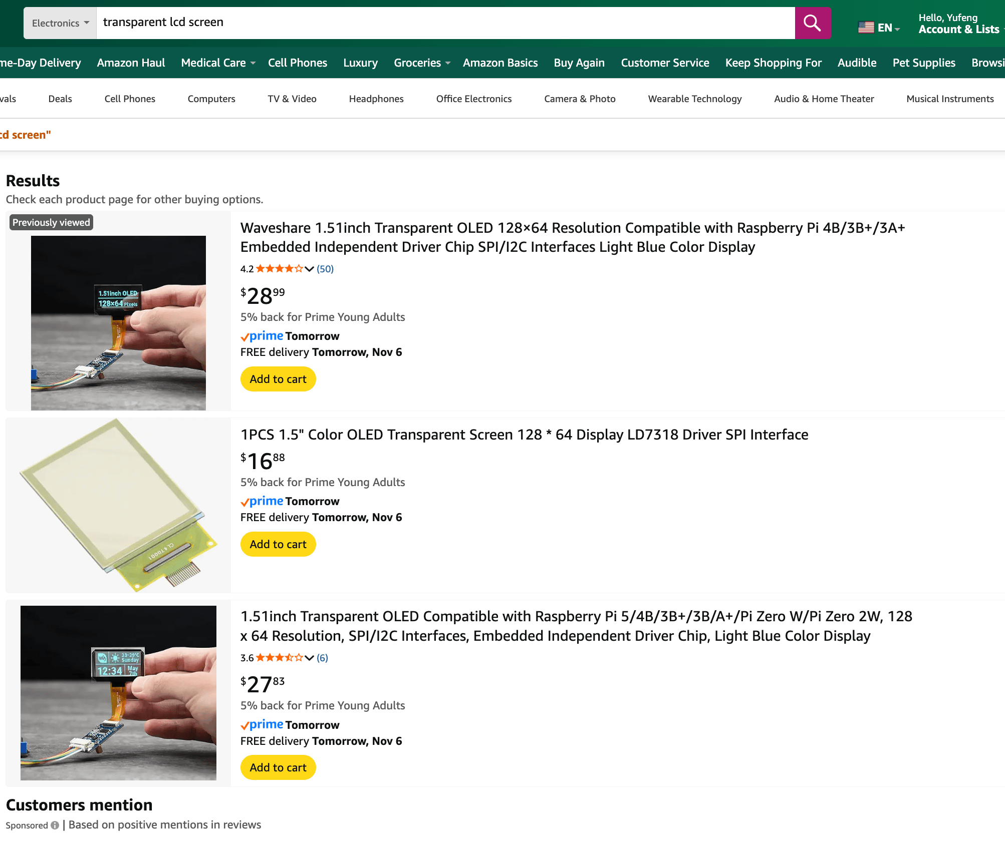
If you search on Amazon, you will only find OLED screens, which is emmisive / additive and not suitable for subtracting light from the already bright projection light source.
The best one I found is this one from Waveshare. It has a nice size comparable to a 35mm film slide, and it's SPI interface, which is easy to interface with a microcontroller.
Something from Fab Inventory
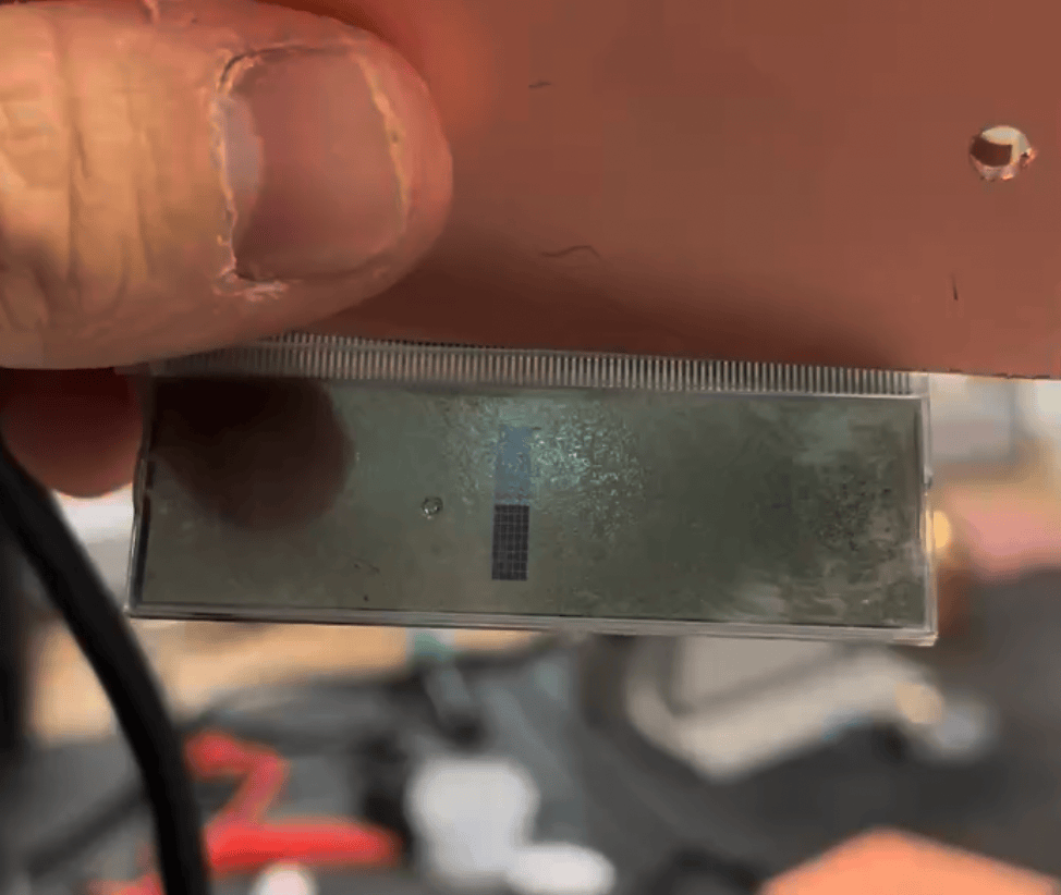
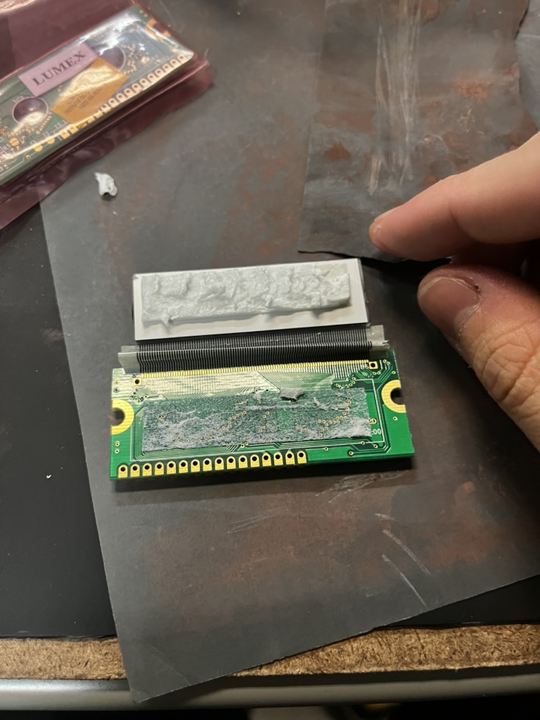
I found a Lumex LCM-S01602DTR/M LCD screen in the fab inventory. It's a TFT LCD screen, and the back looks easy to peel off.
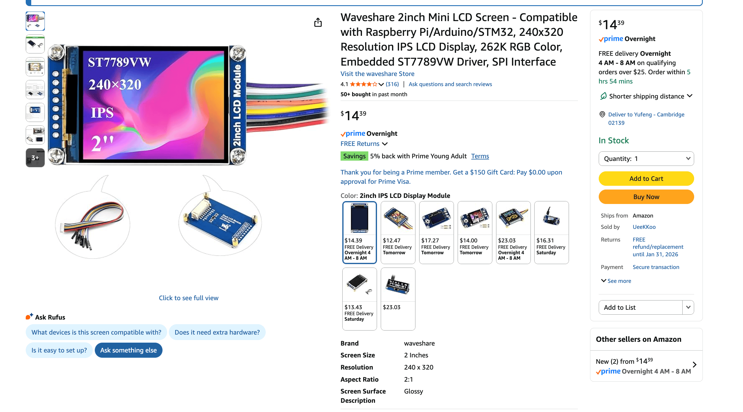
Well, if you look at the back of the package, it says "DO NOT TOUCH THE POLARIZER OR REFLECTOR". But I'm doing it anyway to find out it probably doesn't work the hard way.
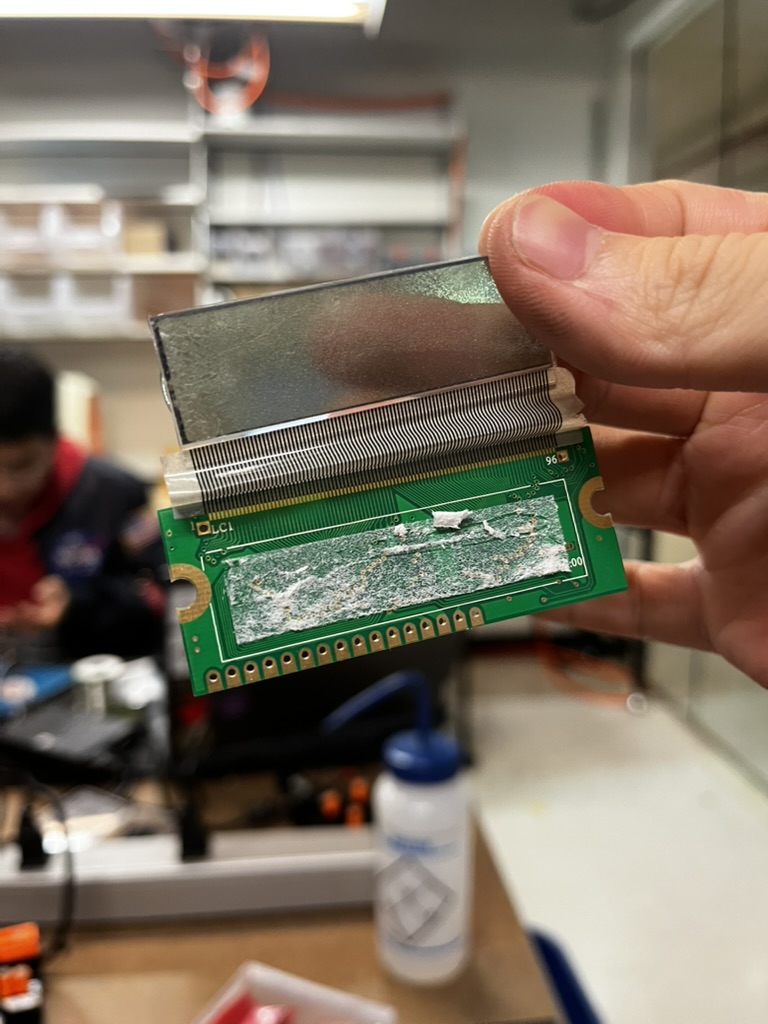
Peel off the polarizer and reflector
We are peeling off the polarizer and reflector to see if it will block light properly through a light source.
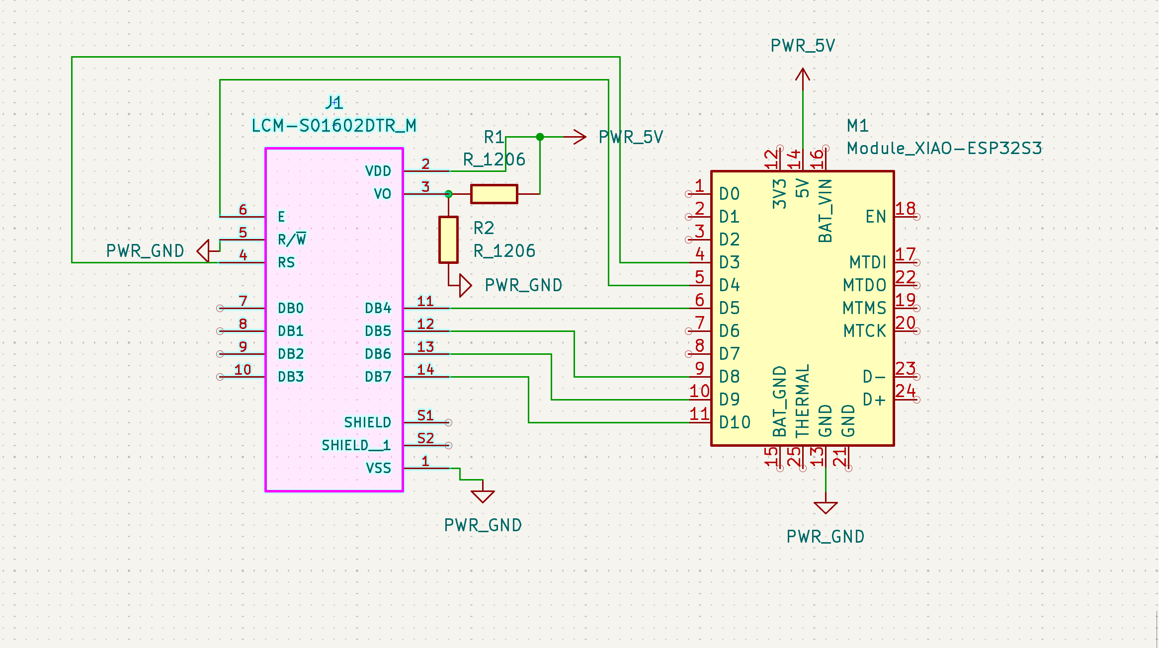
Wiring the LCD screen
I have a XIAO ESP32 S3 Sense board in hand for my final project, so I can use it to test the LCD screen.
I found the datasheet from Digikey, and the footprint and symbol from SnapMagic.
I fed the datasheet to Claude Sonnet 4.5 and it tells me to connect like this:
LCD Pin | LCD Name | ESP32-S3 Pin | Description |
|---|---|---|---|
1 | VSS | GND | Ground |
2 | VDD | 5V | Power supply |
3 | V0 | Potentiometer | Contrast (0.5V-1.0V) |
4 | RS | GPIO4 | Register Select |
5 | R/W | GND | Read/Write (tie to GND) |
6 | E | GPIO5 | Enable |
7 | D0 | Not connected | Not used in 4-bit mode |
8 | D1 | Not connected | Not used in 4-bit mode |
9 | D2 | Not connected | Not used in 4-bit mode |
10 | D3 | Not connected | Not used in 4-bit mode |
11 | D4 | GPIO6 | Data bit 4 |
12 | D5 | GPIO7 | Data bit 5 |
13 | D6 | GPIO8 | Data bit 6 |
14 | D7 | GPIO9 | Data bit 7 |
15 | LED+ | 5V + resistor | Backlight positive (optional) |
16 | LED- | GND | Backlight negative (optional) |
After importing the footprint and symbol to KiCad, I connected the pins like above.
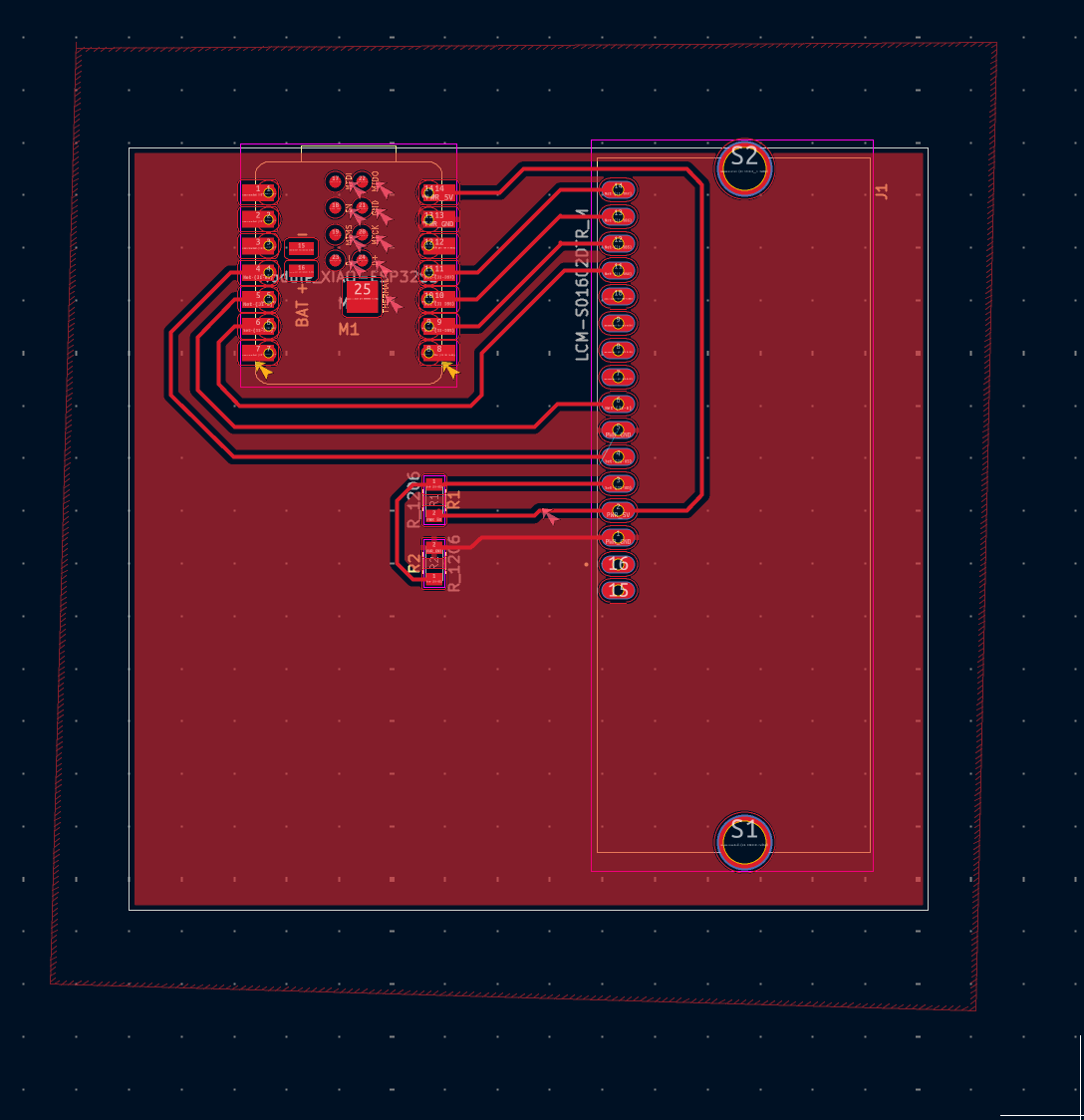
Making the PCB
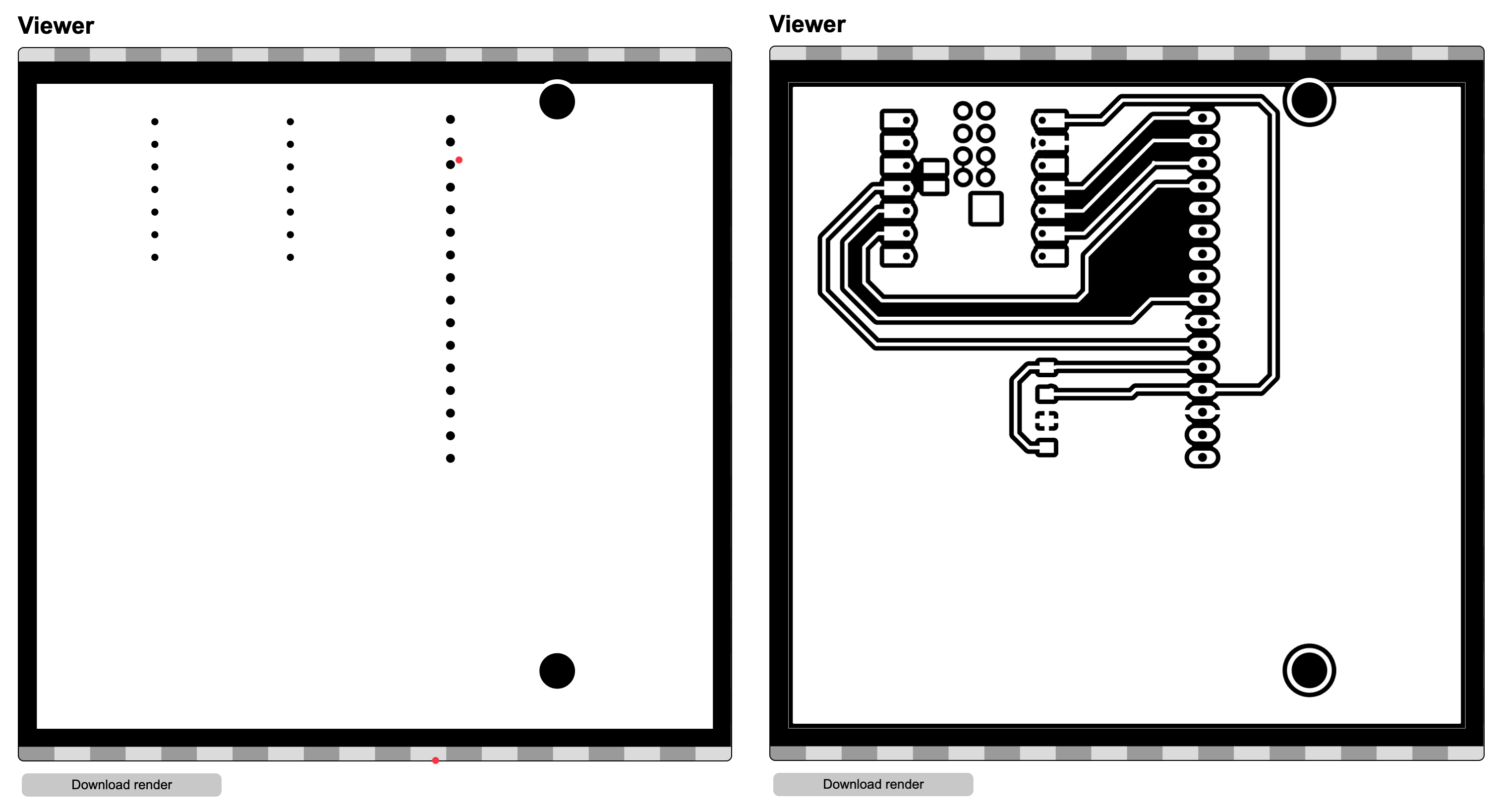
I made these black and white images from the Gerber files.
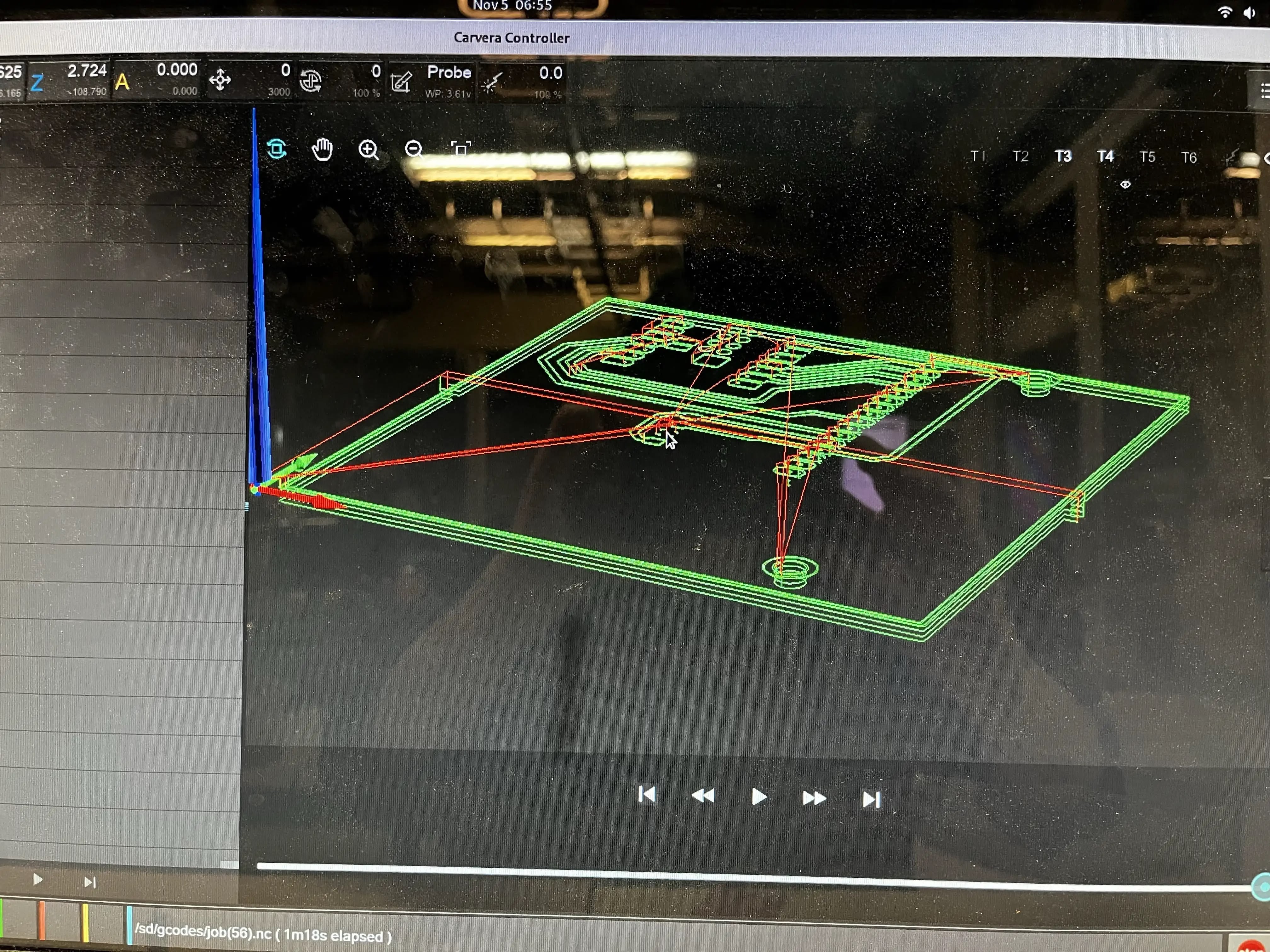
Then I make the toolpath for the Carvera machine on modsproject.com.
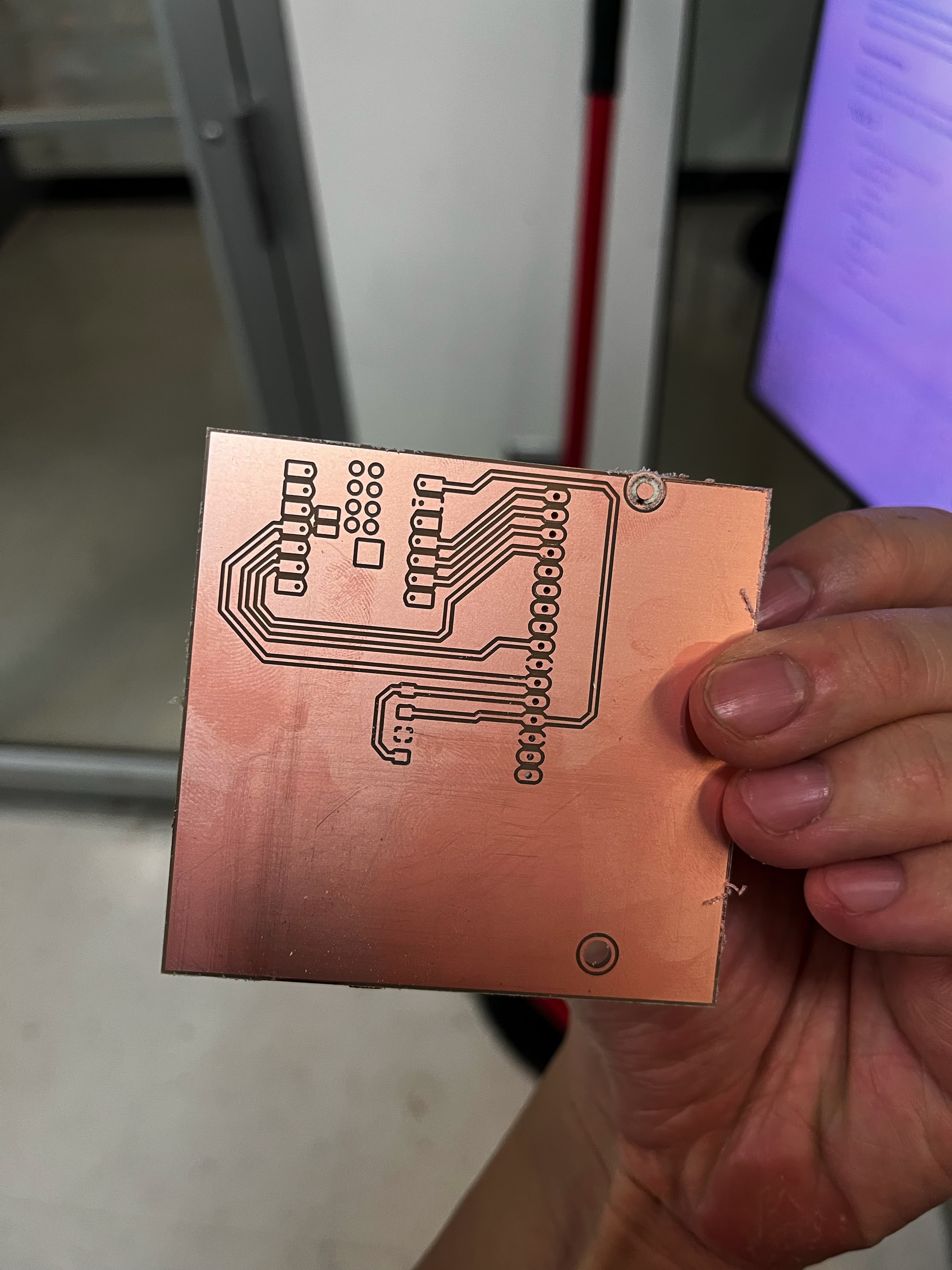
Then I got the PCB done! (will write about some problems later)
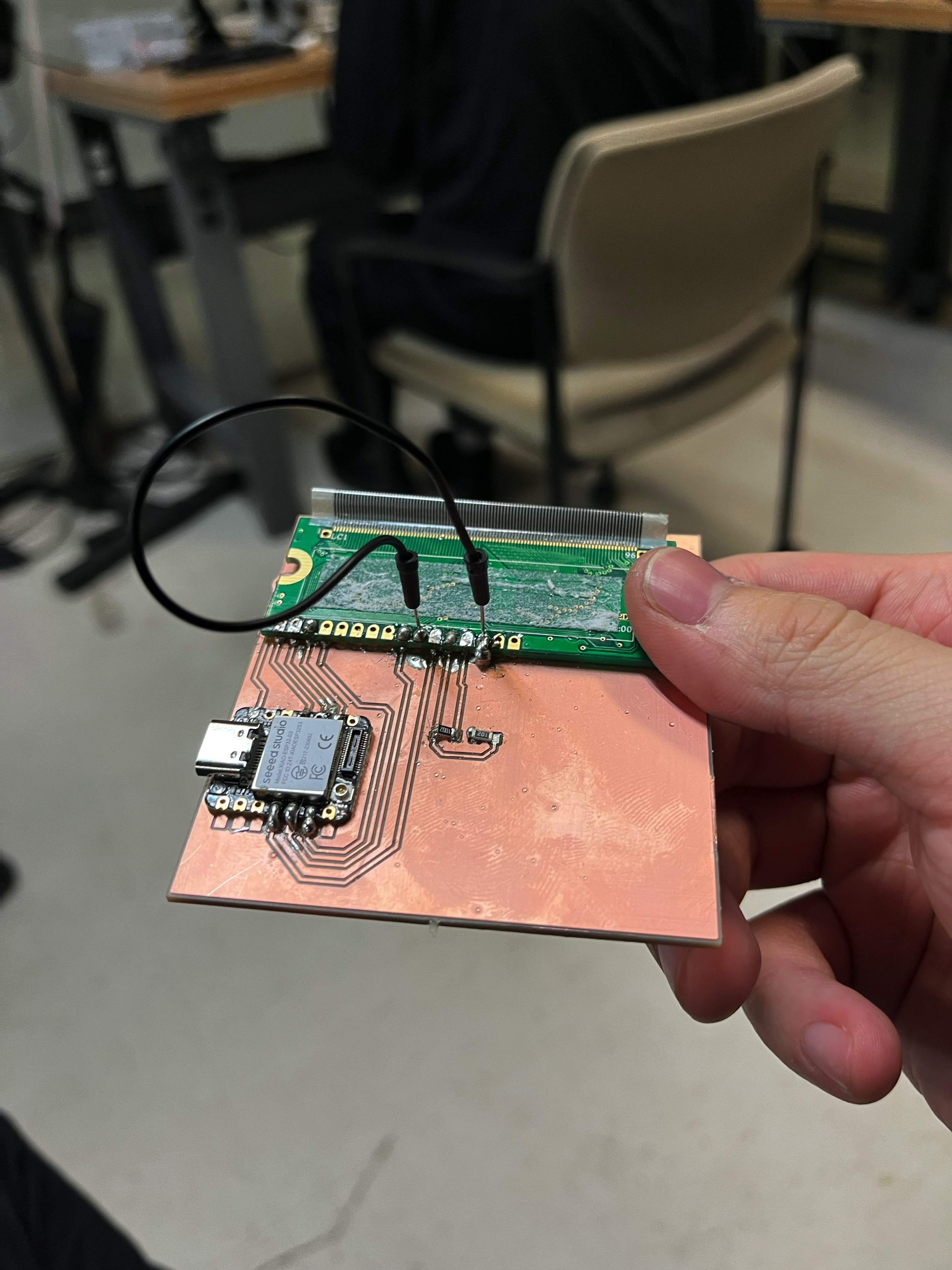
Then I spent a lot of time soldering the components on the PCB. I couldn't figure out how to solder the RS pin to the ground without touching other pins. So I ended up soldering a jumper wire to the RS pin.
Testing the LCD screen
I put a test program on the XIAO ESP32 S3 Sense board to test the LCD screen. It's using the LiquidCrystal library to control the LCD screen, and it displays a pingpong block bouncing back and forth.
#include <LiquidCrystal.h>

LiquidCrystal lcd(4, 5, 6, 7, 8, 9);

int col = 0;
int row = 0;
int dirCol = 1;  // 1 = right, -1 = left
int dirRow = 1;  // 1 = down, -1 = up

void setup() {
  lcd.begin(16, 2);
  lcd.clear();
}

void loop() {
  lcd.clear();

  // Draw block
  lcd.setCursor(col, row);
  lcd.write(255);

  // Move diagonally
  col += dirCol;
  row += dirRow;

  // Bounce off left/right edges
  if (col >= 15 || col <= 0) {
    dirCol = -dirCol;
    col = constrain(col, 0, 15);
  }

  // Bounce off top/bottom edges
  if (row >= 1 || row <= 0) {
    dirRow = -dirRow;
    row = constrain(row, 0, 1);
  }

  delay(300);
}
Here's a video of the test program running on the LCD screen. You can see it struggles to display the block properly at an off angle, a classic problem of TFT LCD screens. I think this is because of polarization?
Moment of Truth
I'm testing it in the dark with a phone flashlight. It didn't work... Case closed.
References
- Lumex LCM-S01602DTR/M LCD screen datasheet
- SnapMagic: Lumex LCM-S01602DTR/M LCD screen
- LiquidCrystal library
- Mods
- Gerber2Img
Design Files
- KiCad Project Folder
- Container Schematic, PCB, and Gerber files
- Gerber2Img Folder
- Black and white images from the Gerber files
- Carvera Job File
- Job file for the Carvera machine