Assignment
- individual assignment:
- write an application that interfaces a user with an input &/or output device that you made
Context
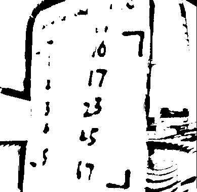
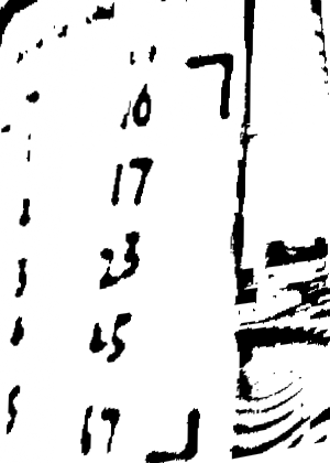
This is part of HyperCarousel, my final project. The HyperCarousel system uses a camera to read handwritten lookup tables on custom slide mounts. Getting the computer vision pipeline to work requires constant iteration — adjusting crop regions, threshold values, and transform parameters. Recompiling and reflashing firmware for every tweak is tedious.
The solution: a web interface served directly from the ESP32S3 that lets me preview the camera feed, adjust parameters live, and see results immediately.
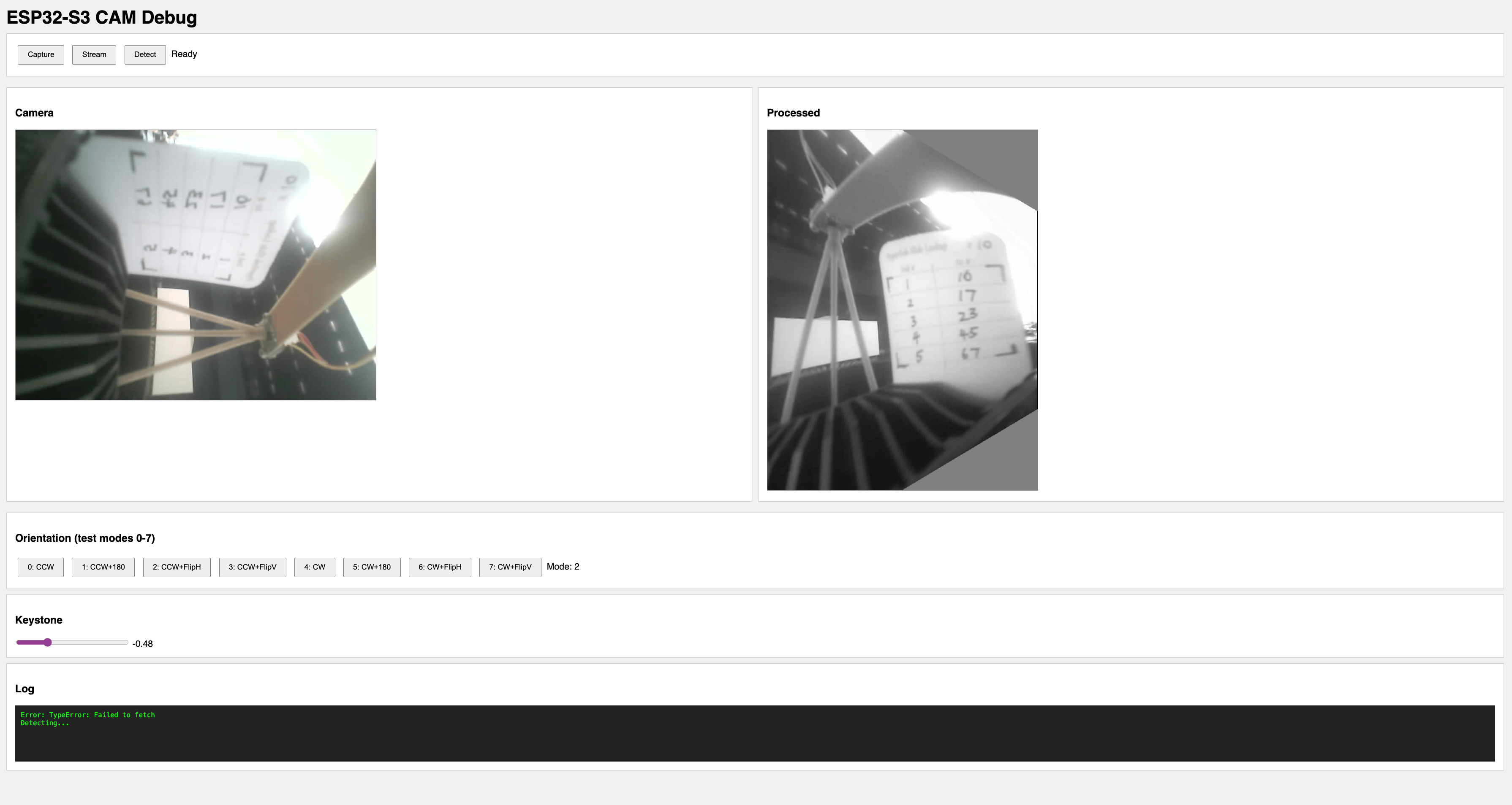
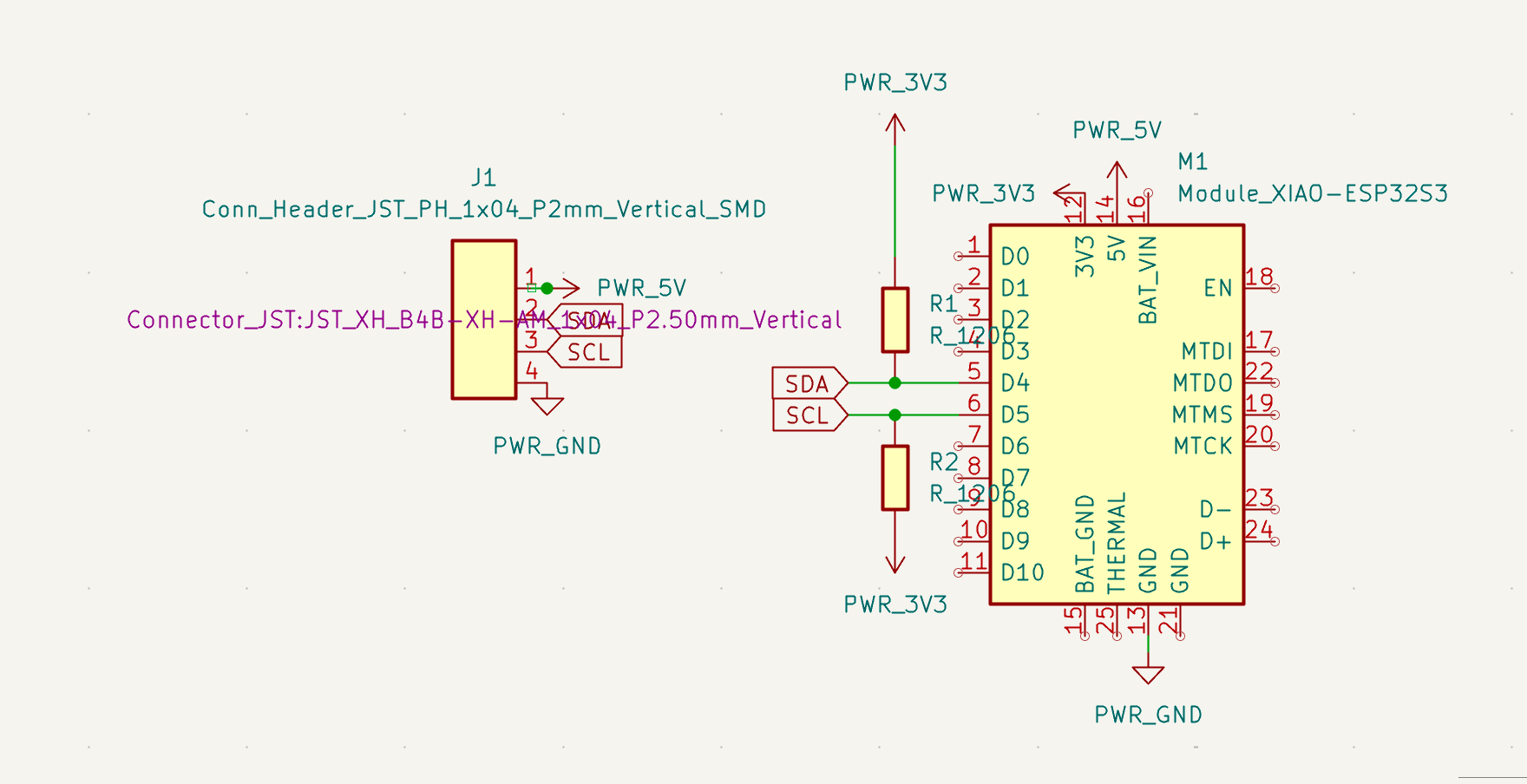
Hardware
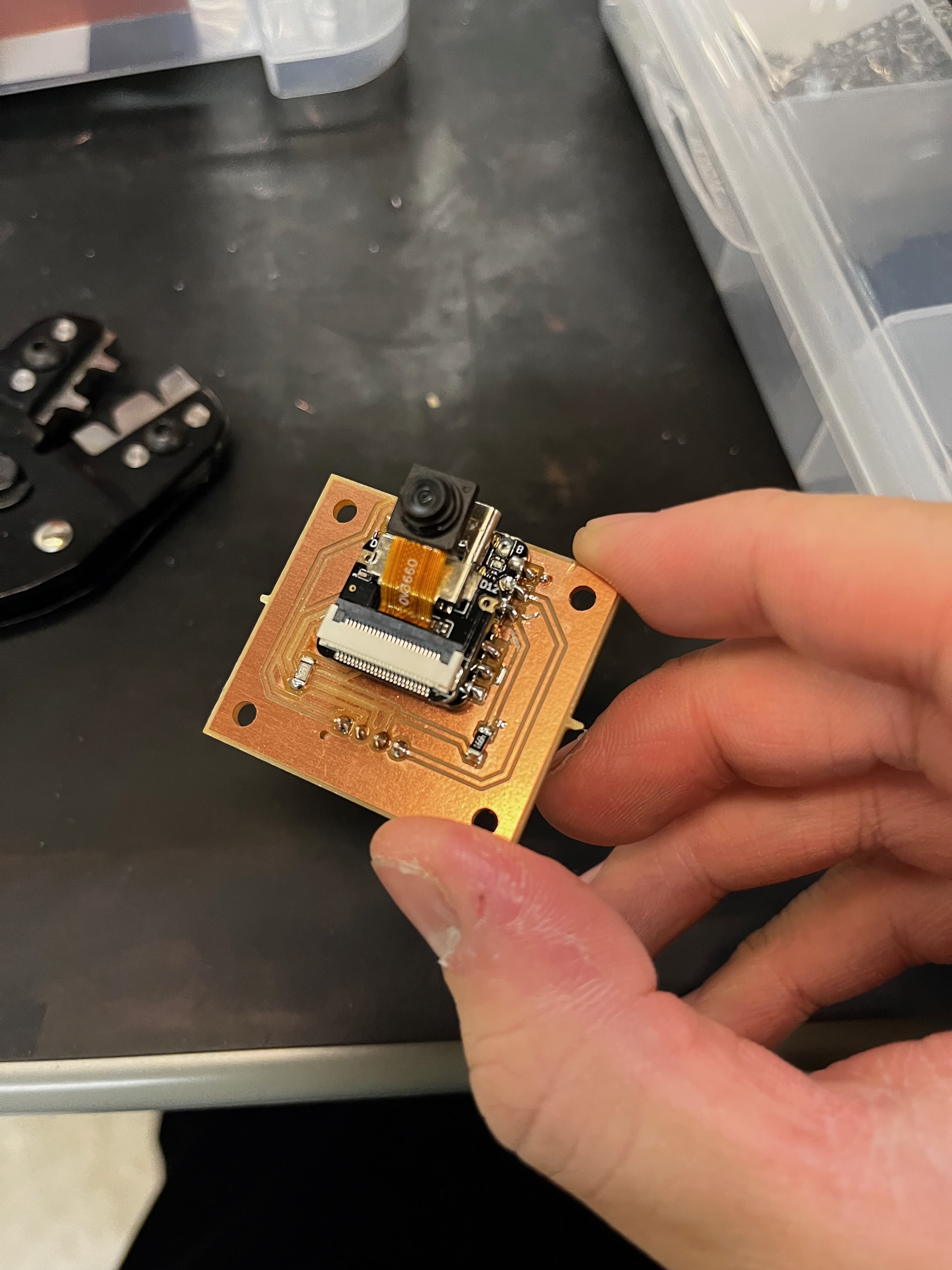
I'm using a Seeed XIAO ESP32S3 Sense — the variant with a detachable OV2640 camera module. The ESP32S3 has enough RAM for image processing and enough flash for serving a web interface.
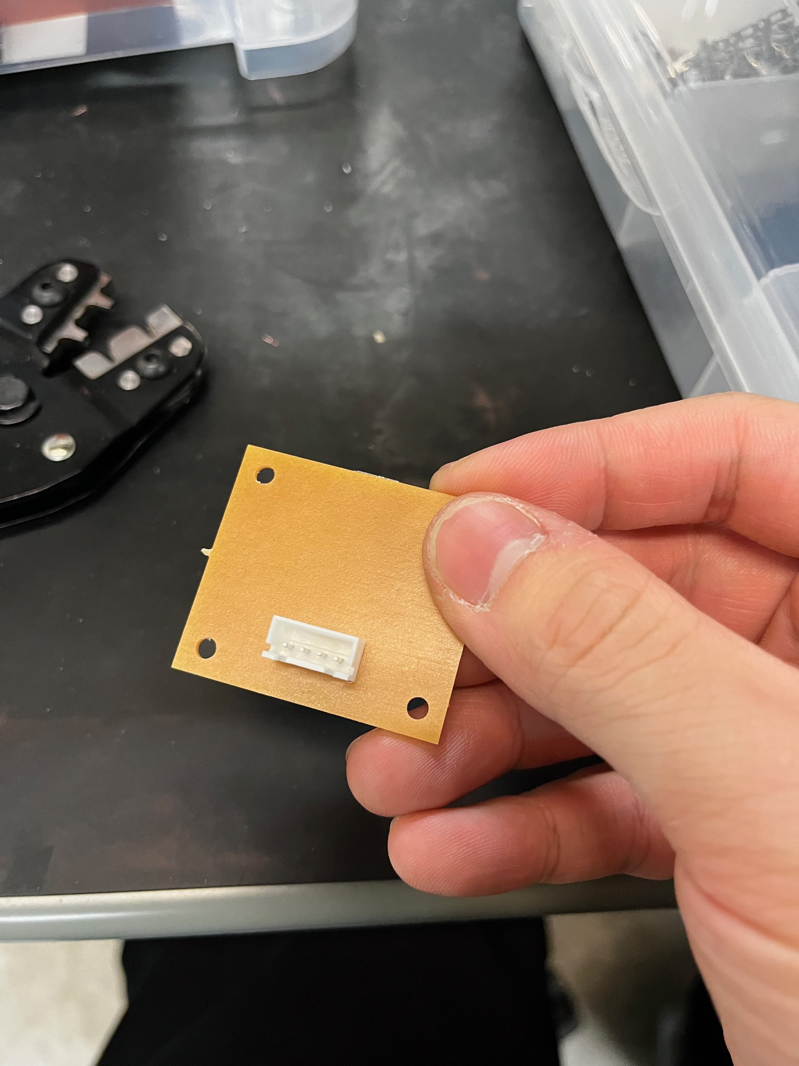
I designed a simple breakout board to expose I2C for communication with the main controller:
What Needs Debugging
The CV pipeline reads handwritten digits from a lookup table. It has five stages, and each stage has parameters that need tuning:
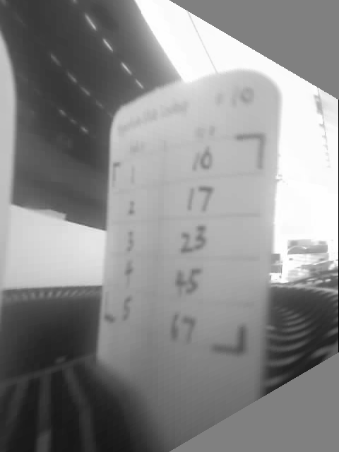
Step 1: Crop — Remove borders to focus on the card area. Crop percentages depend on camera mounting position.
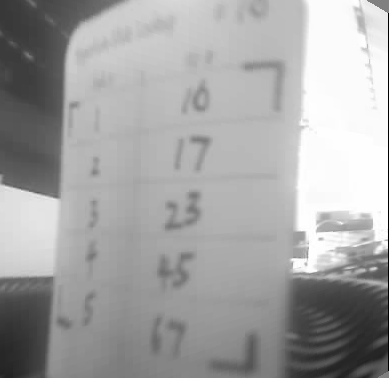
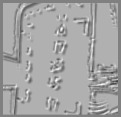
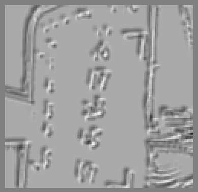
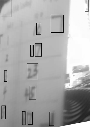
Step 2: Binary threshold — Adaptive thresholding converts grayscale to binary. Block size and constant C need tuning.
Step 3: L-mark detection — Custom corner markers for perspective correction. Arm length thresholds affect detection reliability.

Step 4: Perspective transform — Warp the detected quad to a rectangle.
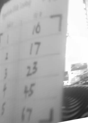
Step 5: Digit recognition — Connected component analysis and heuristic classification.
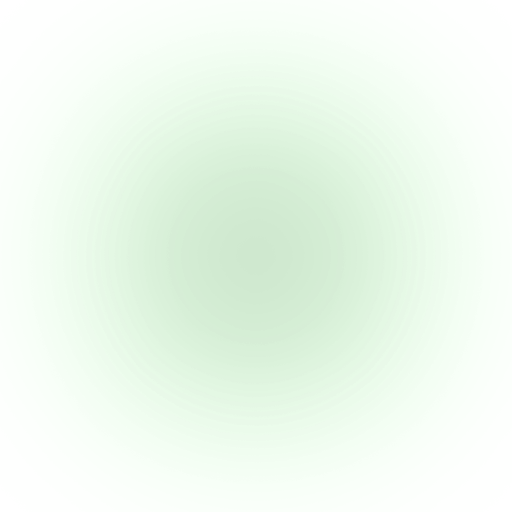
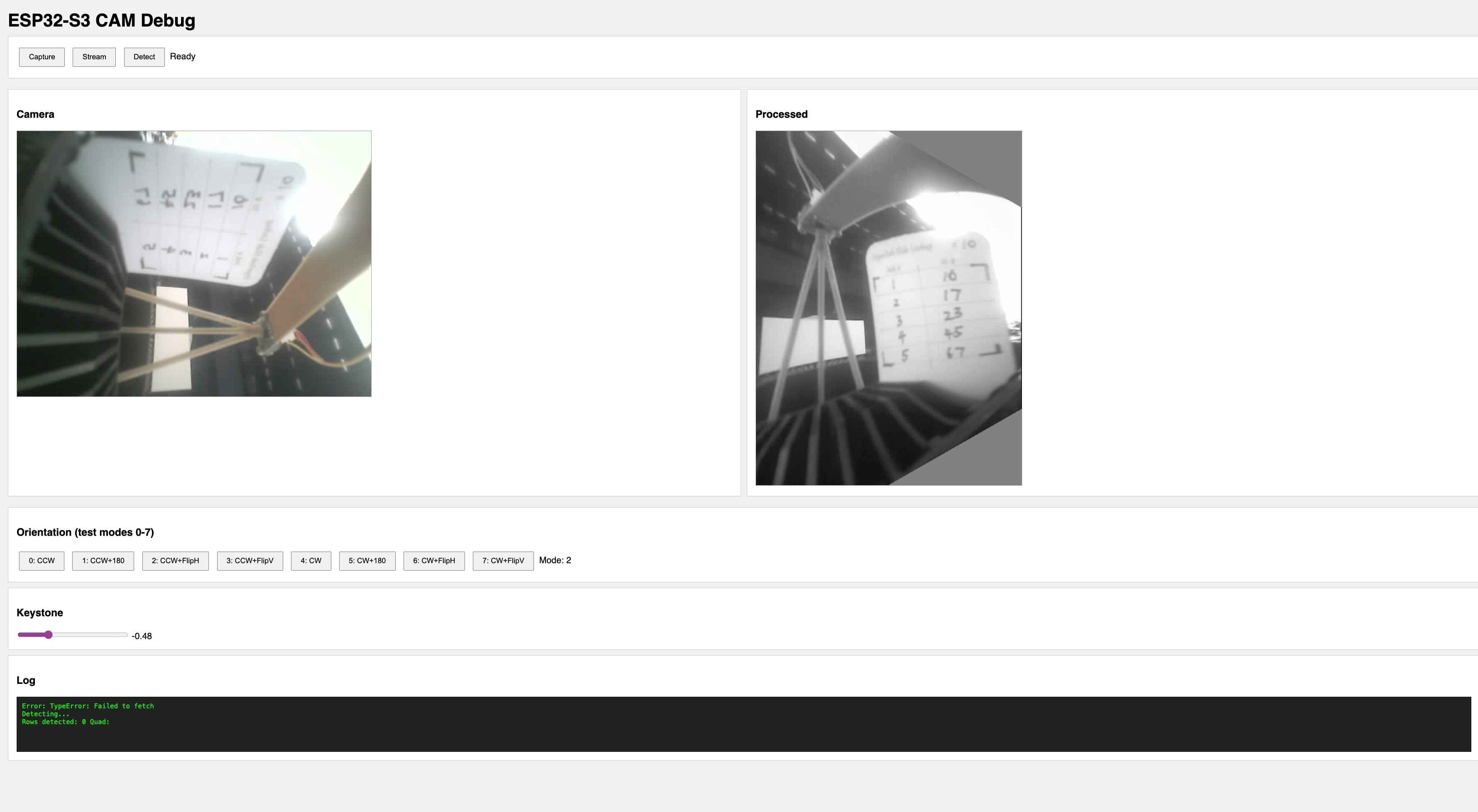
The Web Interface
The ESP32S3 runs a web server that serves an HTML/JS interface. The interface fetches processed images from the device and displays them in the browser.
Key Features
Orientation controls — The camera is mounted sideways, so the image needs rotation. But I wasn't sure which combination of rotation and flip would give the correct orientation. The interface offers 8 combinations (90° CW/CCW × none/180°/flipH/flipV) so I can find the right one without recompiling.
Keystone correction slider — If the camera isn't perfectly perpendicular to the card, the image appears trapezoidal. The slider applies a horizontal keystone transform to correct this.
Live preview — The browser polls the ESP32S3's /processed endpoint, which returns raw grayscale bytes with dimensions in HTTP headers. JavaScript renders them to a canvas.
Implementation
The server exposes several endpoints:
Endpoint | Returns |
|---|---|
/ | HTML/JS interface |
/raw | Raw camera JPEG |
/processed | Grayscale with transforms applied |
/debug | Intermediate pipeline stages (for testing) |
/orient | Set orientation mode (0-7) |
/keystone | Set keystone correction value |
The /processed handler applies the configured transforms:
void handleProcessed() {
  GrayImage gray, rotated, transformed;
  if (!captureGray(gray)) { server.send(500, "text/plain", "capture failed"); return; }

  // Apply configured rotation (camera is mounted sideways)
  (orientMode < 4) ? rotate90CCW(gray, rotated) : rotate90CW(gray, rotated);

  // Apply secondary transform based on mode
  int subMode = orientMode % 4;
  switch (subMode) {
    case 0: transformed = std::move(rotated); break;
    case 1: rotate180(rotated, transformed); break;
    case 2: flipH(rotated, transformed); break;
    case 3: flipV(rotated, transformed); break;
  }

  // Apply keystone if set
  if (keystoneVal != 0.0f) keystoneH(transformed, output, keystoneVal);

  // Send with dimensions in headers
  server.sendHeader("X-Width", String(output.width));
  server.sendHeader("X-Height", String(output.height));
  server.send(200, "application/octet-stream", output.data, output.size());
}
The frontend renders grayscale bytes directly to canvas:
async function updatePreview() {
  const res = await fetch("/processed");
  const width = parseInt(res.headers.get("X-Width"));
  const height = parseInt(res.headers.get("X-Height"));
  const data = new Uint8Array(await res.arrayBuffer());

  const canvas = document.getElementById("preview");
  canvas.width = width;
  canvas.height = height;
  const ctx = canvas.getContext("2d");
  const imgData = ctx.createImageData(width, height);

  for (let i = 0; i < data.length; i++) {
    imgData.data[i * 4] = data[i]; // R
    imgData.data[i * 4 + 1] = data[i]; // G
    imgData.data[i * 4 + 2] = data[i]; // B
    imgData.data[i * 4 + 3] = 255; // A
  }
  ctx.putImageData(imgData, 0, 0);
}
Cloud OCR Fallback
I also added a cloud fallback for when on-device recognition fails. The ESP32S3 can POST the processed image to a Vercel serverless function that calls Google Cloud Vision API:
// Vercel API route - /api/ocr
export async function POST(request: Request) {
  const { image } = await request.json();
  const client = new vision.ImageAnnotatorClient();
  const [result] = await client.textDetection({ image: { content: image } });

  // Extract numbers from right column based on x-position
  const numbers = result.textAnnotations
    ?.filter((a) => /^\d+$/.test(a.description || ""))
    .filter((a) => a.boundingPoly?.vertices?.[0]?.x > imageWidth * 0.6)
    .map((a) => parseInt(a.description));

  return Response.json({ numbers });
}
This didn't work well either — Google Vision concatenates all digits instead of parsing the table structure — but the interface made it easy to test and rule out.
Reflection
Building this debug interface was more valuable than the CV algorithm itself. Every time I made a change to the pipeline, I could see the result immediately in my browser. No compile-flash-wait cycle.
The ugly emoji buttons in the screenshot? I vibe-coded the frontend and the ESP32's web server doesn't handle UTF-8 correctly. The interface looks broken but functions fine. Good enough for debugging.
The interface also revealed problems I wouldn't have caught otherwise — like discovering that my keystone correction was being applied in the wrong direction, or that certain lighting conditions caused the L-mark detector to find false positives in the film transparency area.
Design Files
- ESP32-S3 Camera OCR Source Code (.zip) — PlatformIO project with CV pipeline, web interface, and cloud OCR integration