HyperCarousel is an add-on for the Kodak Carousel projectors and a novel slide mount design (HyperSlide) to add hypertext non-linear navigation capabilities to the slide projector. It's also a case study in how idealistic design goals crash into reality.
Origins
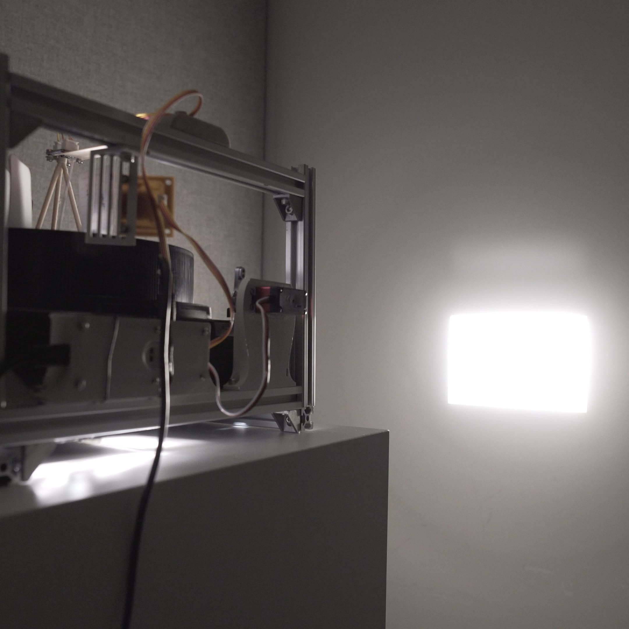
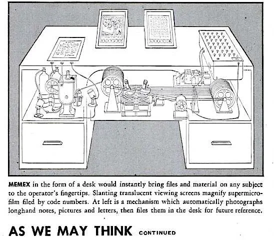
This project traces back to Week 1 and a DIY projector I built in Shanghai in 2021. I asked myself a question that seemed simple at the time: what if someone actually built Vannevar Bush's Memex using 1945 technology?
Week 1 me was idealistic: "If I can do it purely mechanical, I wouldn't go electrical. If I have to go electrical, I wouldn't go electronic." Famous last words.
System Architecture
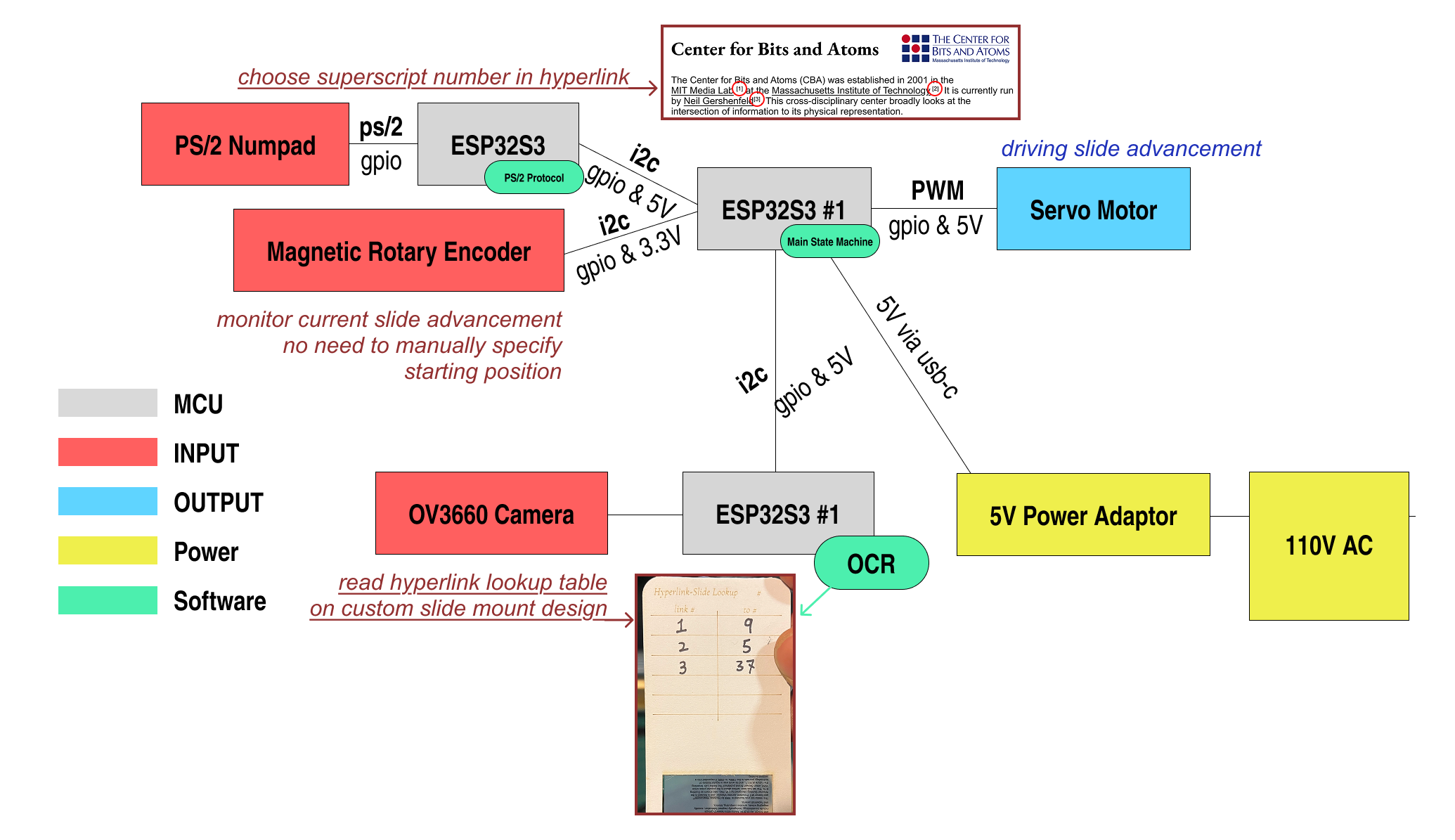
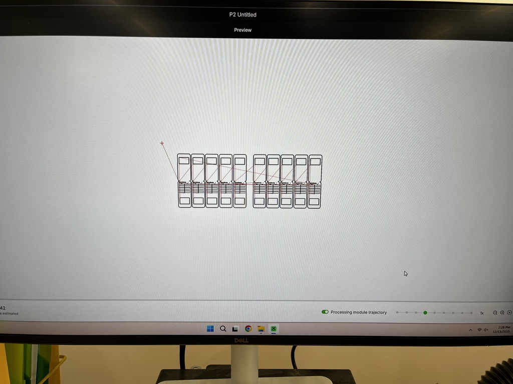
Here's what I proposed in Week 9:
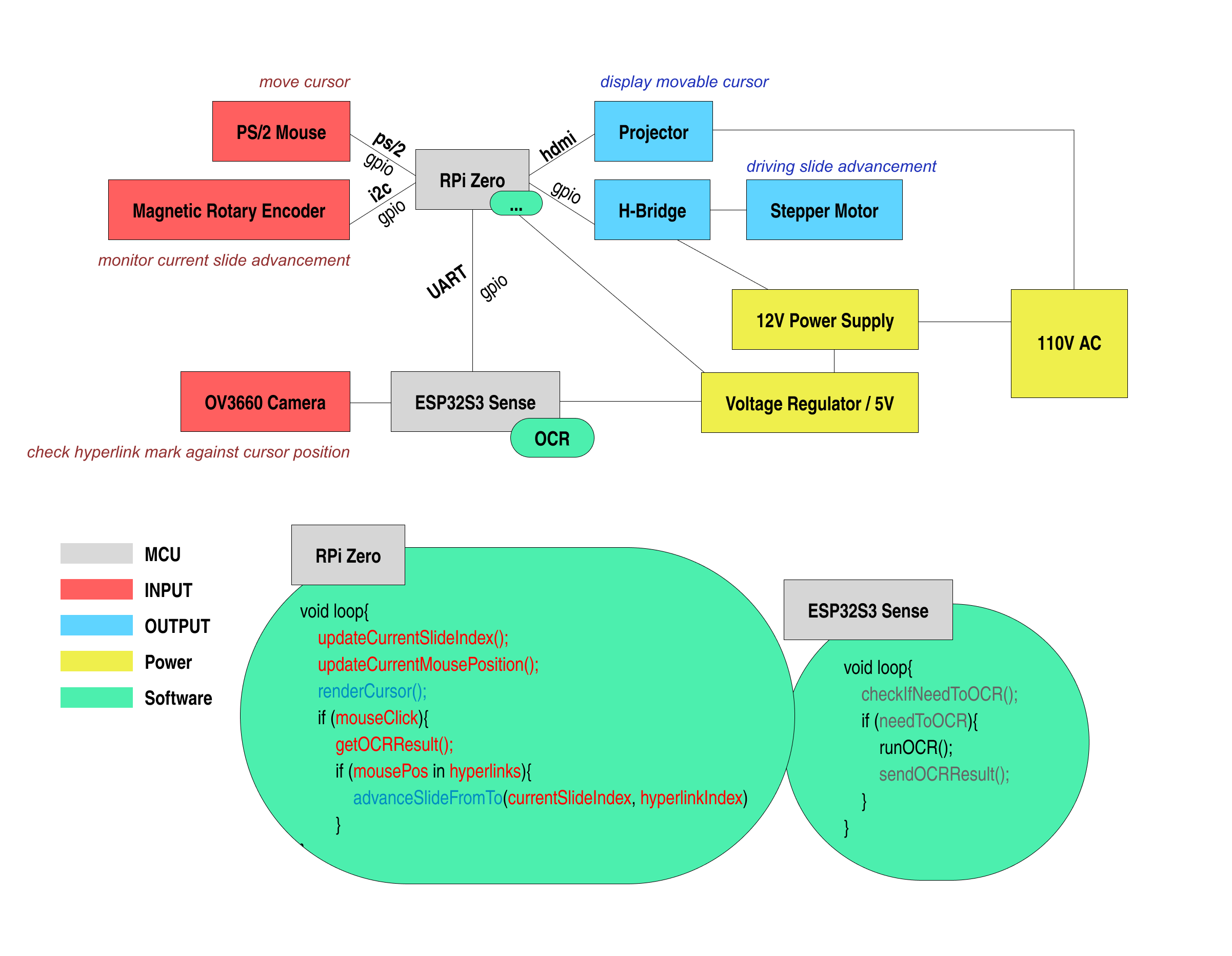
And here's what I actually built:
What Changed
Aspect | Plan | Reality |
|---|---|---|
Controller | RPi Zero | ESP32S3 |
Input | PS/2 Mouse | PS/2 Numpad |
Cursor | HDMI Projector overlay | None |
Motor | Stepper + H-Bridge + Geneva | Servo pressing buttons |
Power | 12V + regulator | 5V USB-C |
The cursor died first. I spent weeks thinking about how to overlay a mouse cursor onto the projected image. Turns out projectors can't focus on two slides at once — my overlay idea failed in 30 seconds of actual testing. Should've tried that earlier. No cursor means no mouse, no HDMI, no RPi Zero. The entire top half of my roadmap, gone.
The Geneva mechanism died next. I had romantic visions of a precision-machined Geneva drive controlling the carousel advance. Instead, I'm just... pressing the Carousel's existing buttons with a servo arm. It's the dumbest possible solution. It also works.
So Much for Low-Tech
The creator workflow stayed analog — printed transparencies, laser-cut cardstock, handwritten lookup tables. But the system itself? Multiple ESP32s, I2C buses, computer vision. Firmly electronic. Week 1 me would be disappointed.
The honest take: HyperCarousel is a digital device that enables an analog workflow. Not the "purely mechanical" dream I romanticized in Week 1, but it's the compromise that actually ships. Sometimes you have to kill your darlings to finish the project.
HyperSlide Design
HyperSlide is a custom slide mount design that enables hypertext navigation in the Kodak Carousel. Each slide mount contains a handwritten lookup table that maps hyperlink numbers to destination slide numbers — essentially metadata attached to each slide. Think of it as a punchcard, but human-readable.
This section chronicles four design iterations. Spoiler: the fourth one still doesn't fully work.
V0: Testing the Waters
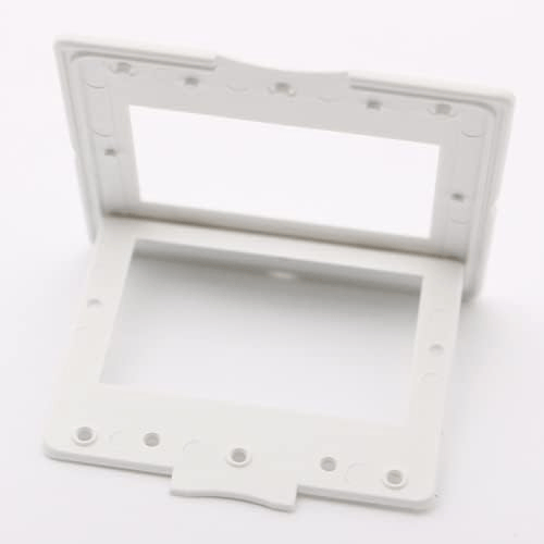
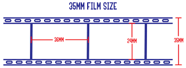
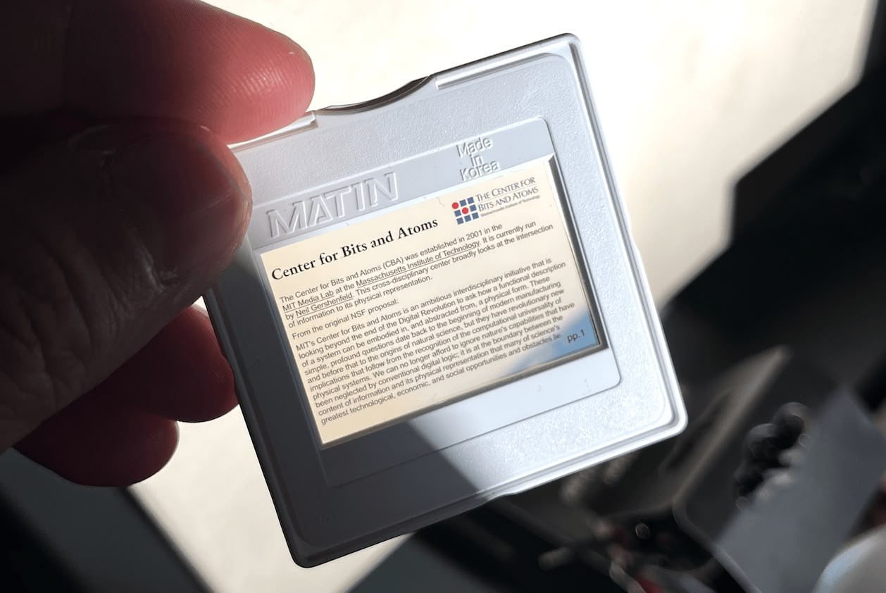
Before designing anything, I needed to understand what I was working with. I bought Matin 35mm Slide Mounts 100 Pieces - Glassless White to understand the physical constraints of slide mounts. I checked some references on slide film dimensions. According to "How to Tell Which Type of Slides You Have" by Dillon Wallace, the 35mm film imaging size is 36mm × 24mm, but the entire film for one shot including the sprocket holes is 36mm × 35mm.
For the transparency film, I bought Caydo 8.5 x 11 Inch A4 Transparent Film for Screen Printing (I got the A3 11×17 inch version, but they no longer sell that variant).
I designed in Figma at 1px = 1mm scale, exported at 4× resolution, and printed on 11×17 paper at 100% scale.
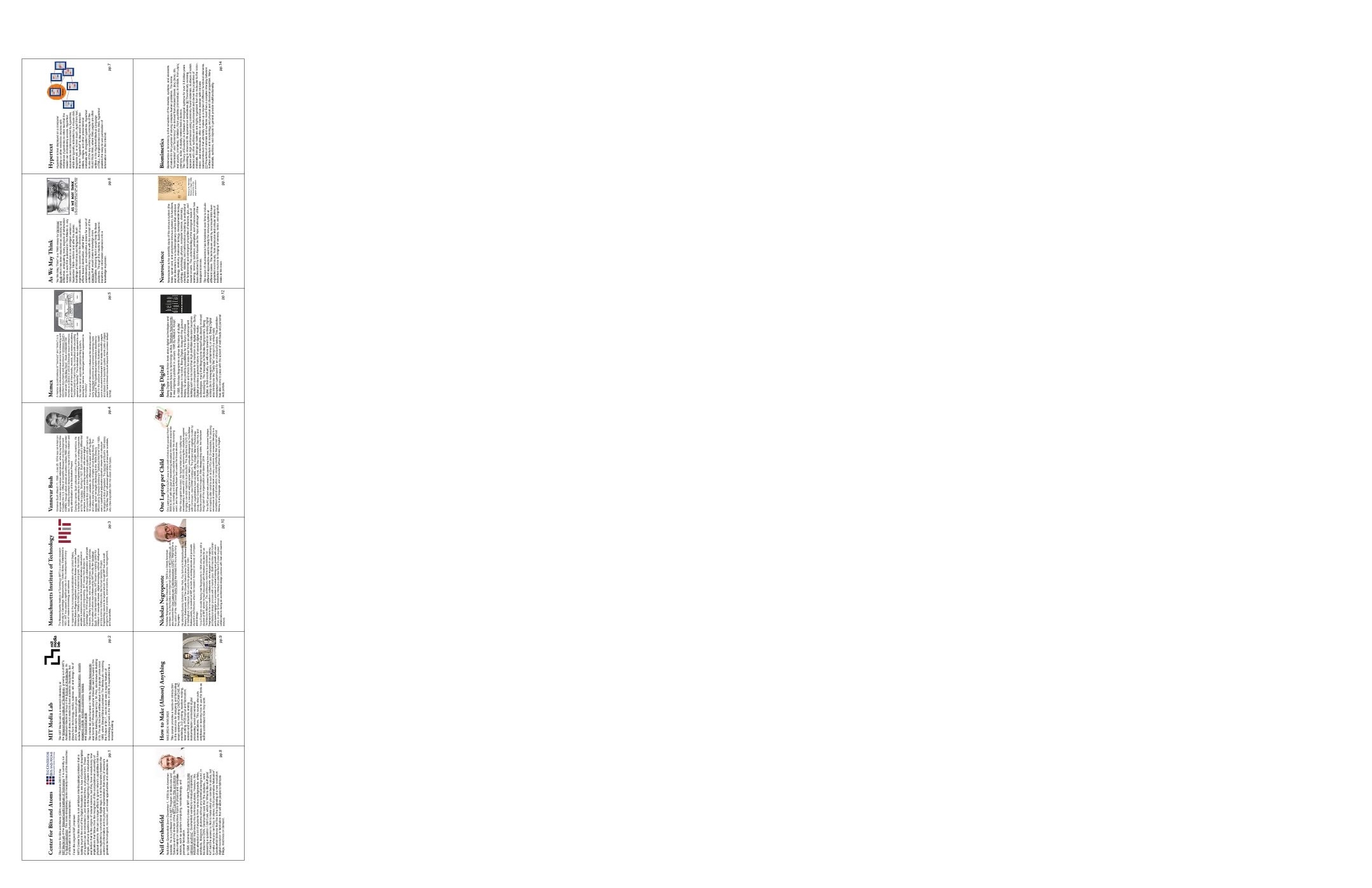
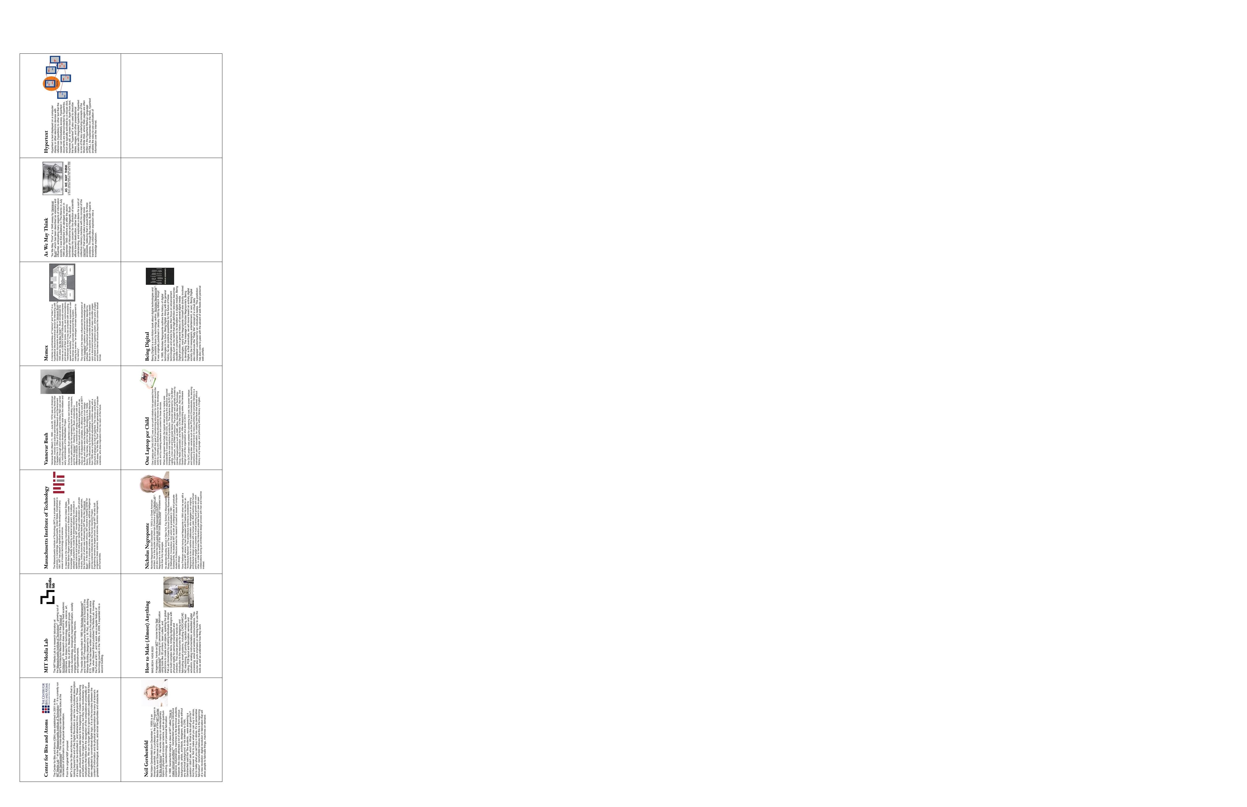
The content of these slides is mostly sourced from Wikipedia. Text that's underlined indicates hyperlinks connecting to other slides.
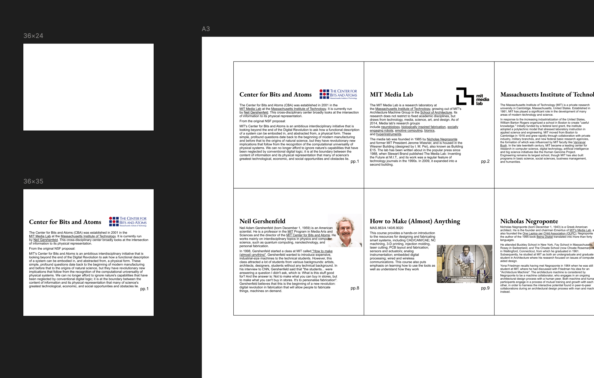
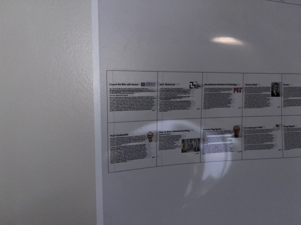
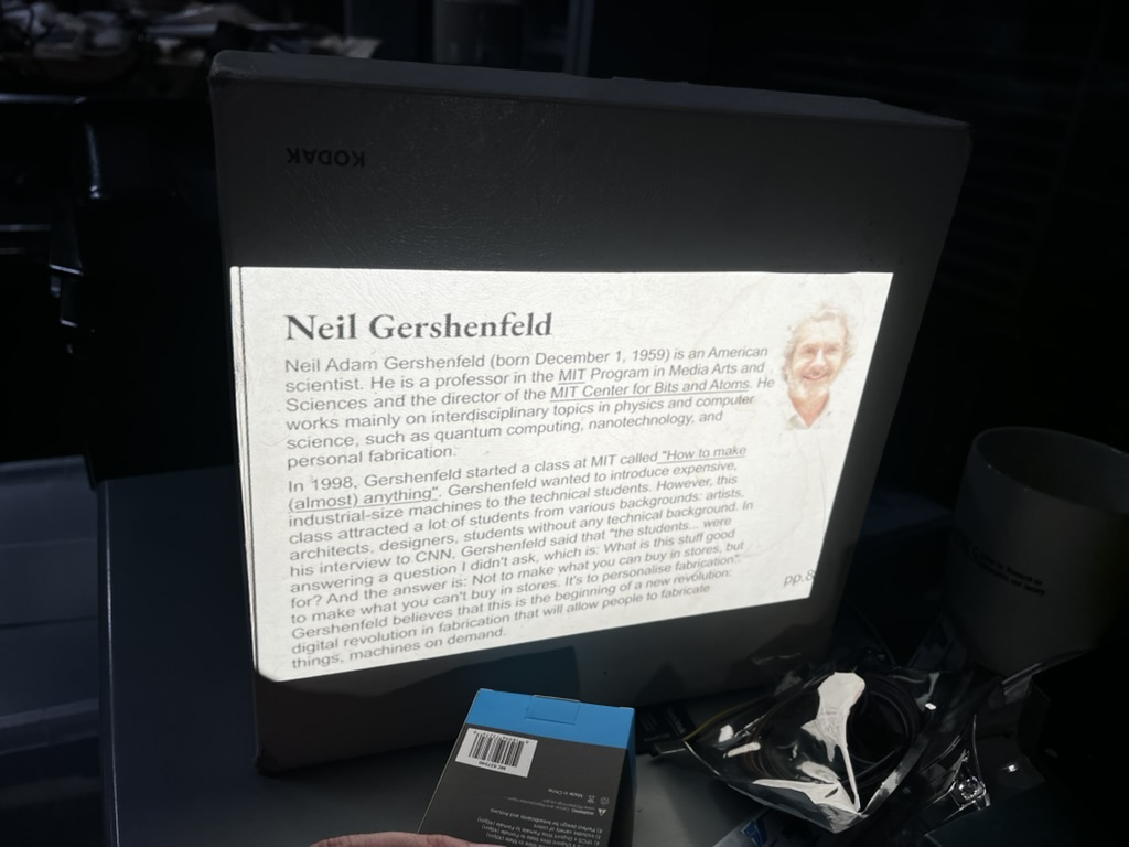
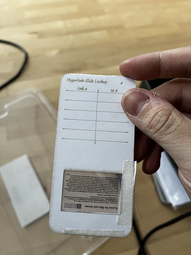
Here's a slide about Center for Bits and Atoms mounted in a Matin mount, and a slide about Neil Gershenfeld projected through the Kodak Carousel 600:
Download V0 design (4× resolution)
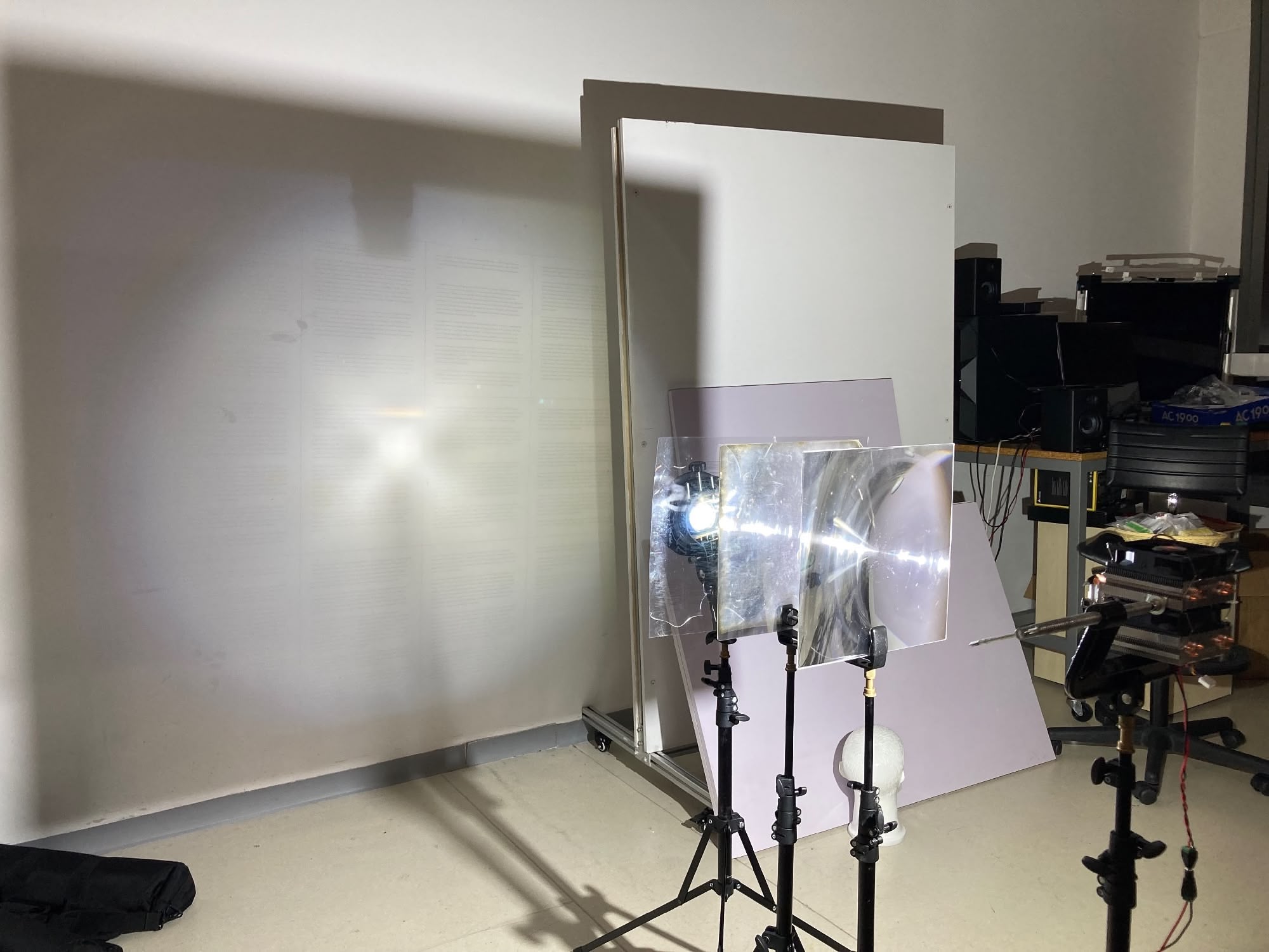
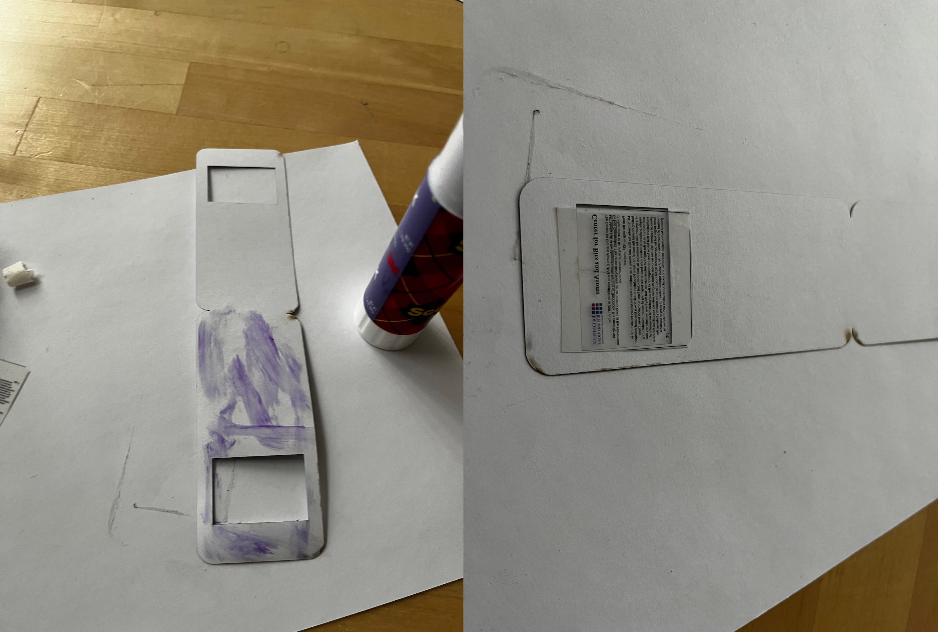
Here's where my cursor idea died. In the original roadmap, I wanted to use a mouse/trackball interaction to control a cursor overlaid on the projected image. So I did some testing — I drew a cursor on an empty piece of slide and put both the Neil slide and cursor slide into the projector at the same time.
Turns out (obviously, in hindsight) the projector can only focus on one focal plane. When the content slide is sharp, the cursor is blurry. When the cursor is sharp, the content is blurry. There's no winning here without serious optical engineering I'm not equipped to do.
This 30-second test killed weeks of planning. RIP cursor idea. The numpad & lookup table approach was the fallback that became the main design.
V1: The Punchcard Inspiration
I was originally dead set on using punchcards. The IBM Punchcard was a well-established standard, and I wanted everything as analog as possible. I even found a variation with a slide embedded in a punchcard — these are called aperture cards, used for archiving blueprints with machine-readable metadata. Basically exactly what I want to achieve here, except it already existed in the 1960s.
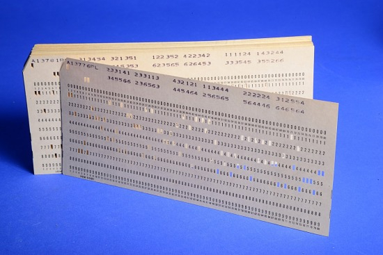
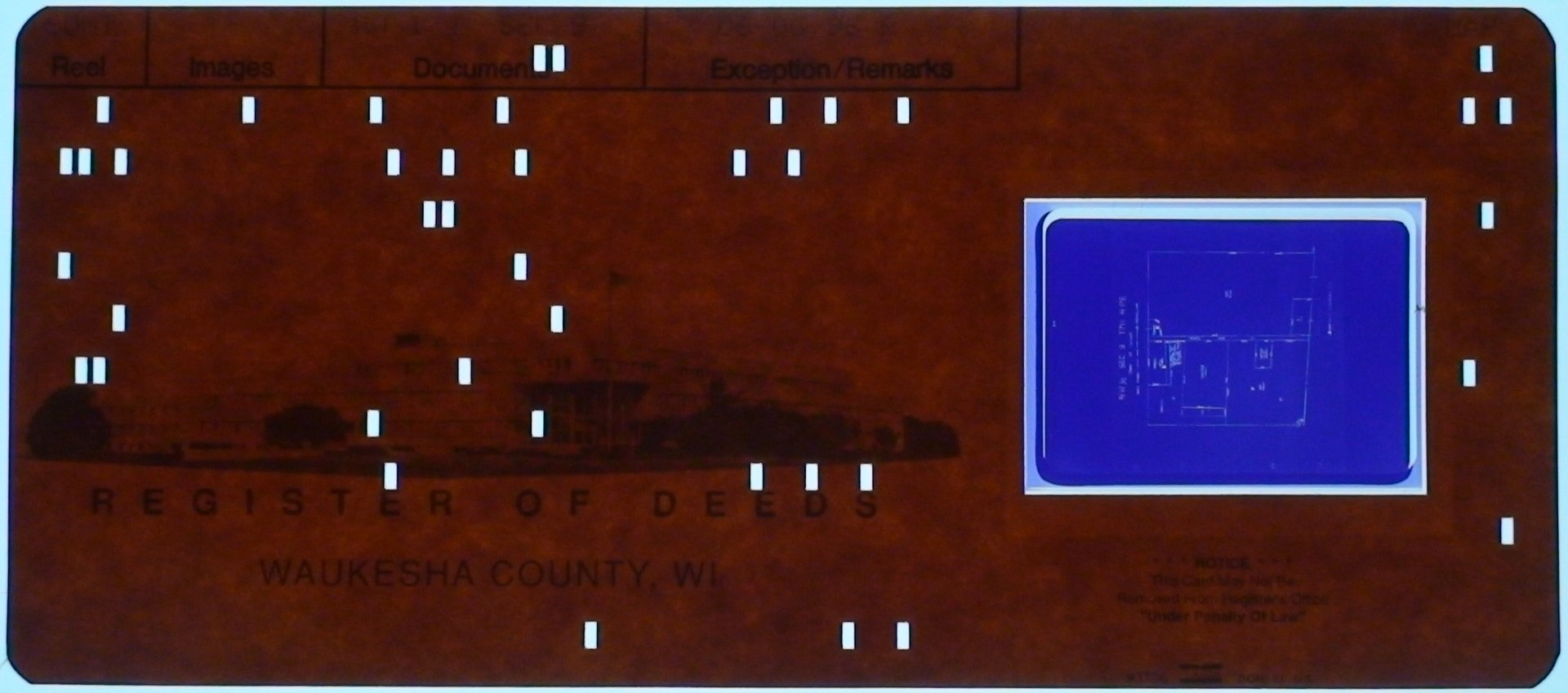
But then I'd need optical sensors to read the punches, plus a whole mechanical punch system for the user to create them. I wasn't ready to die on this hill — that's a semester-long project in itself.
So I compromised: instead of machine-punched holes, I'd use a camera to read human-readable handwritten numbers. A person can just write the lookup table on the slide mount with a pen. Less elegant than punchcards, but infinitely more practical for a prototype.
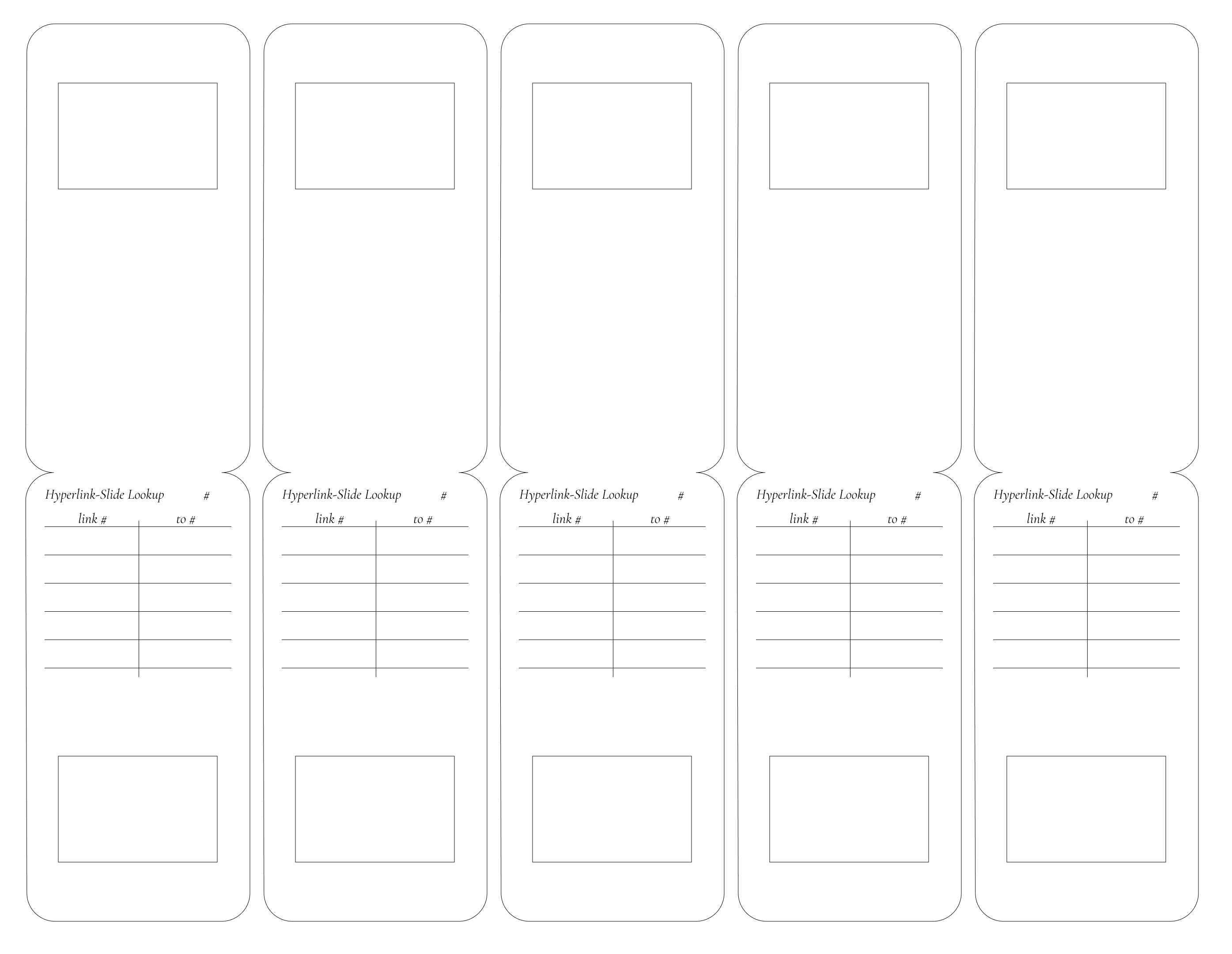
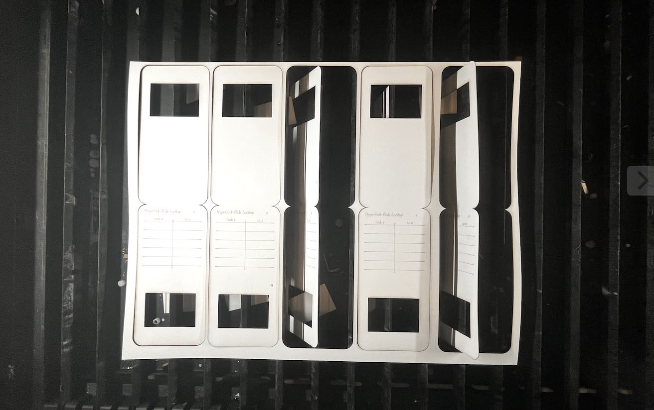
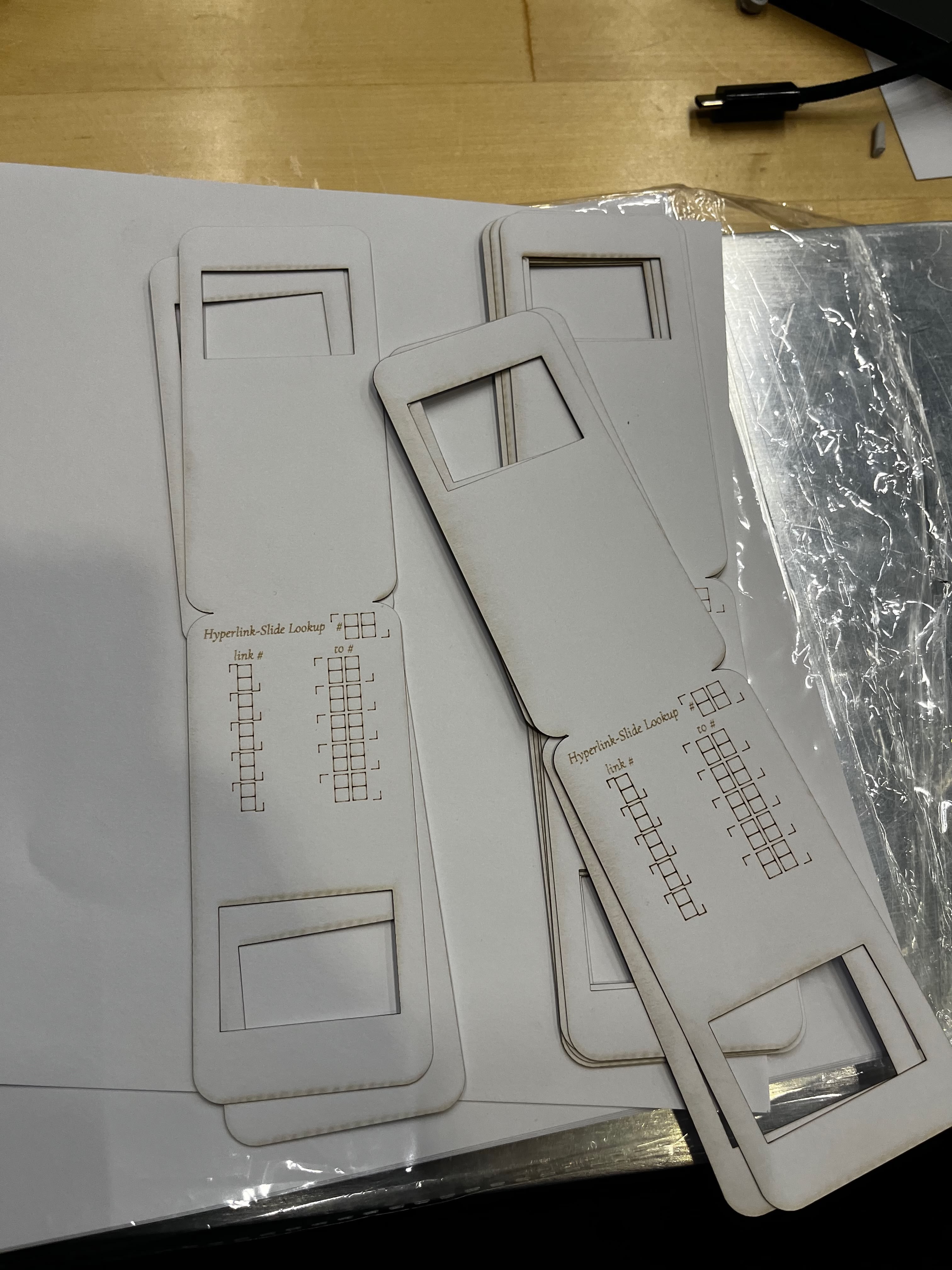
So this is my design: 5 mounts laid out on a letter-sized canvas. I made the width the same as the slide mount requirement (2 inch / 51.3mm) and doubled the height to 4 inch (102.6mm). I located the 36×24mm film cutout at the right location and put a two-column table on top (one says link #, the other says to #).
I used White Cardstock 8.5 x 11, 230gsm Cover Cardstock Paper, 85 Lb Heavy Card for the material.
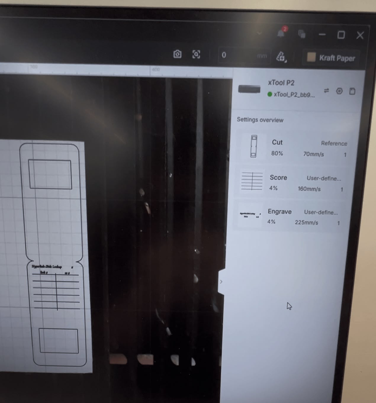
I put my design in the xTool P2 laser cutter. I wanted to engrave the table headers, score the grid lines, and cut the mount contour. The xTool software interpreted everything wrong — I had to manually reassign each element type. Also, my SVG export didn't preserve dimensions (classic Figma-to-laser issue), so I had to manually rescale everything. The width should be 50mm to match the Matin mounts.
Operation | Power | Speed |
|---|---|---|
Cut | 80% | 70mm/s |
Score | 4% | 160mm/s |
Engrave | 4% | 225mm/s |
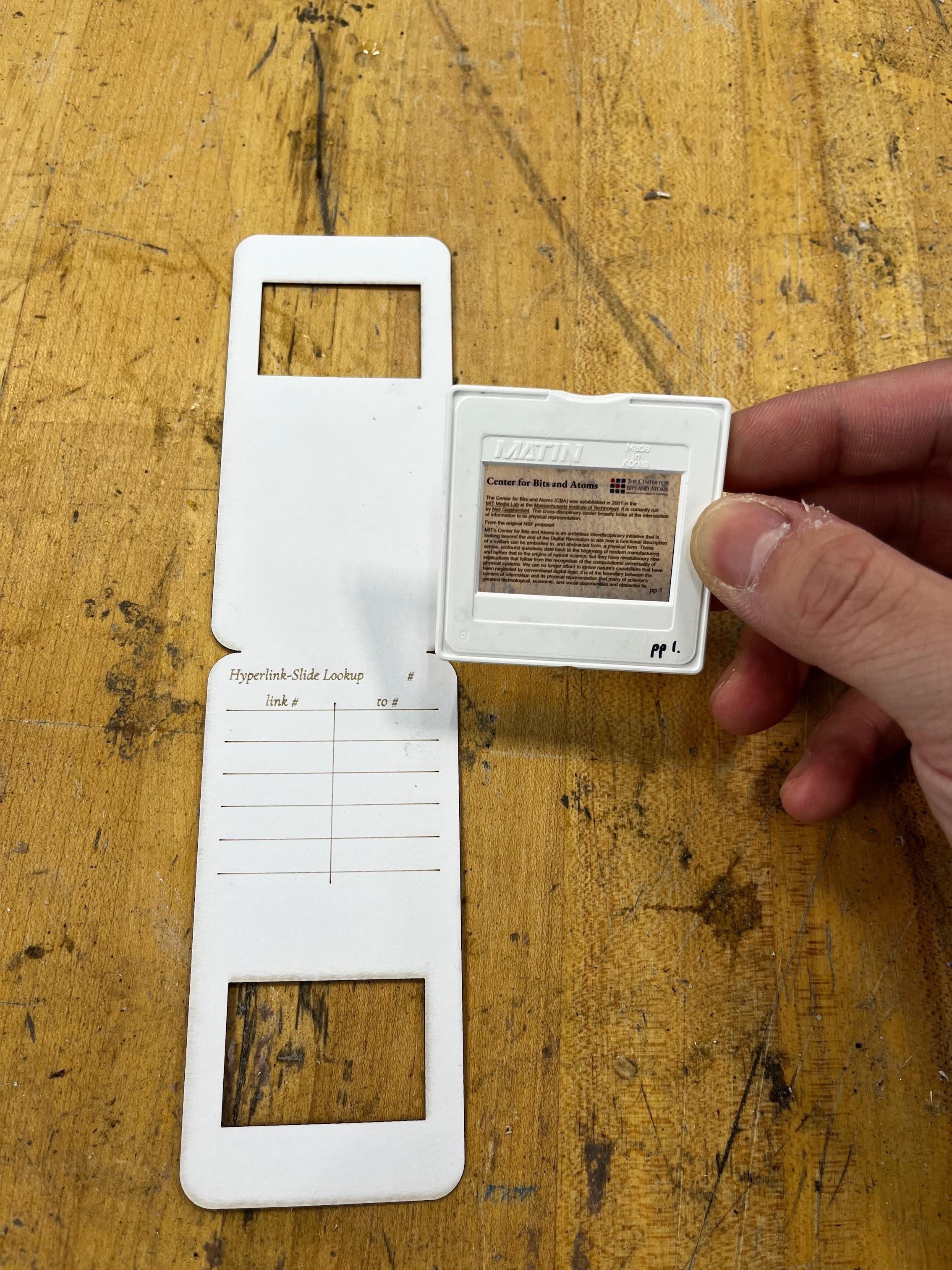
I taped my film and the slide mount together:
Moment of truth: I tested the slide in my projector... and it got stuck halfway.
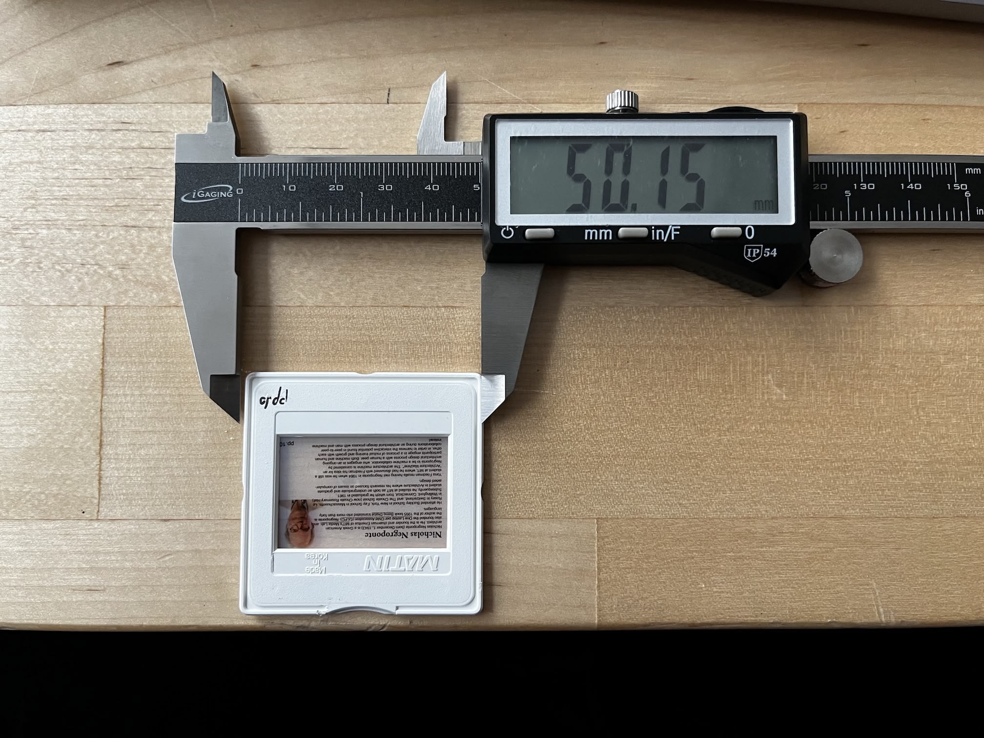
My first instinct: it's too wide. I measured the Matin slide mount with a caliper — 50.15mm. Same as what I designed. But paper isn't plastic. Paper bends and catches on things. Rather than waste more cardstock on another laser session, I just trimmed both sides with scissors.
It worked. The slide goes up and down smoothly now. Sometimes the fastest fix is the least elegant one.
Download V1 design SVG (don't use this though — the width is weird)
V2: Getting the Width Right
Lesson learned: I changed the width from 50mm to 48mm. Two millimeters of tolerance for paper flex. Everything works now without trimming.
I batch-cut ten mounts on two pieces of letter-sized cardstock. I also switched from tape to glue stick for mounting the film — much cleaner, and the bond is more permanent.
Here's a 10× speed timelapse of the cutting process:
V3: Seven-Segment Marking Attempt
Later in the project, my computer vision was struggling to recognize handwritten digits. So I had what I thought was a clever idea: score seven-segment digit guides into the cardstock. Users would trace over the guides, resulting in consistent, recognizable digits.
It backfired. Even at minimum power (200mm/s, 1%), the scoring marks are too dark. The high-contrast burn lines confuse my CV algorithm even more than messy handwriting. The "helpful" guides became noise in the image. I abandoned this approach.
Moral: sometimes your fix makes things worse. More on this disaster in the Lookup Table Recognition section.
V4: Superscript Link Numbers
The previous designs used underlined text to indicate hyperlinks, but there was no clear mapping between the underlined link and the numpad key the user should press. V4 fixes this by adding superscript numbers next to each hyperlink — like academic footnotes (¹, ², ³, etc.). Each superscript directly corresponds to a key on the numpad.
This is a UX improvement on the slide content itself, not the mount. The user now sees "Vannevar Bush¹" and knows to press "1" on the numpad to follow that link. No guessing, no counting underlines.
Download V4 design (4× resolution)
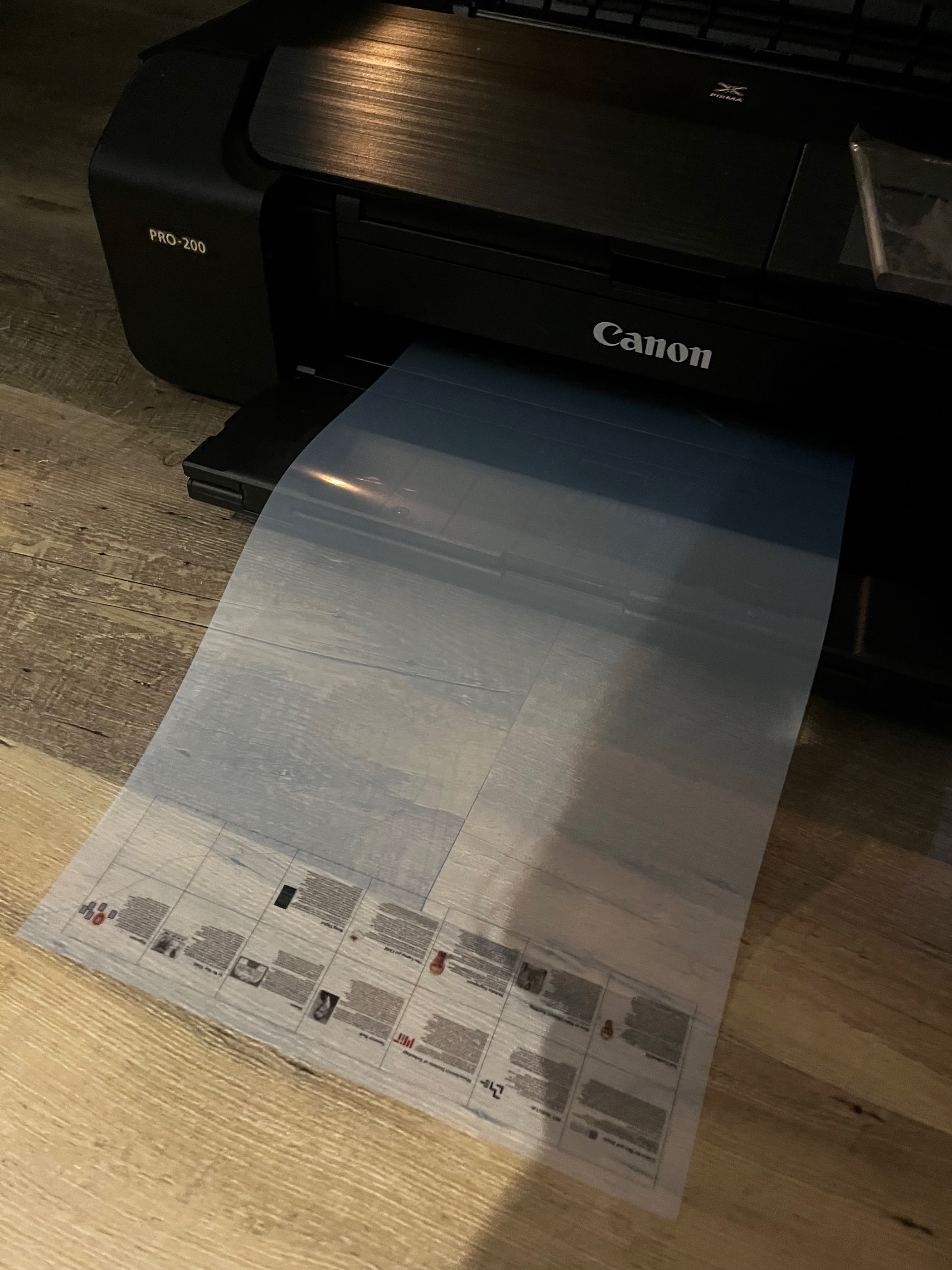
I printed the new slides on transparency film using a Canon PRO-200:
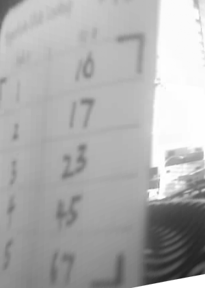
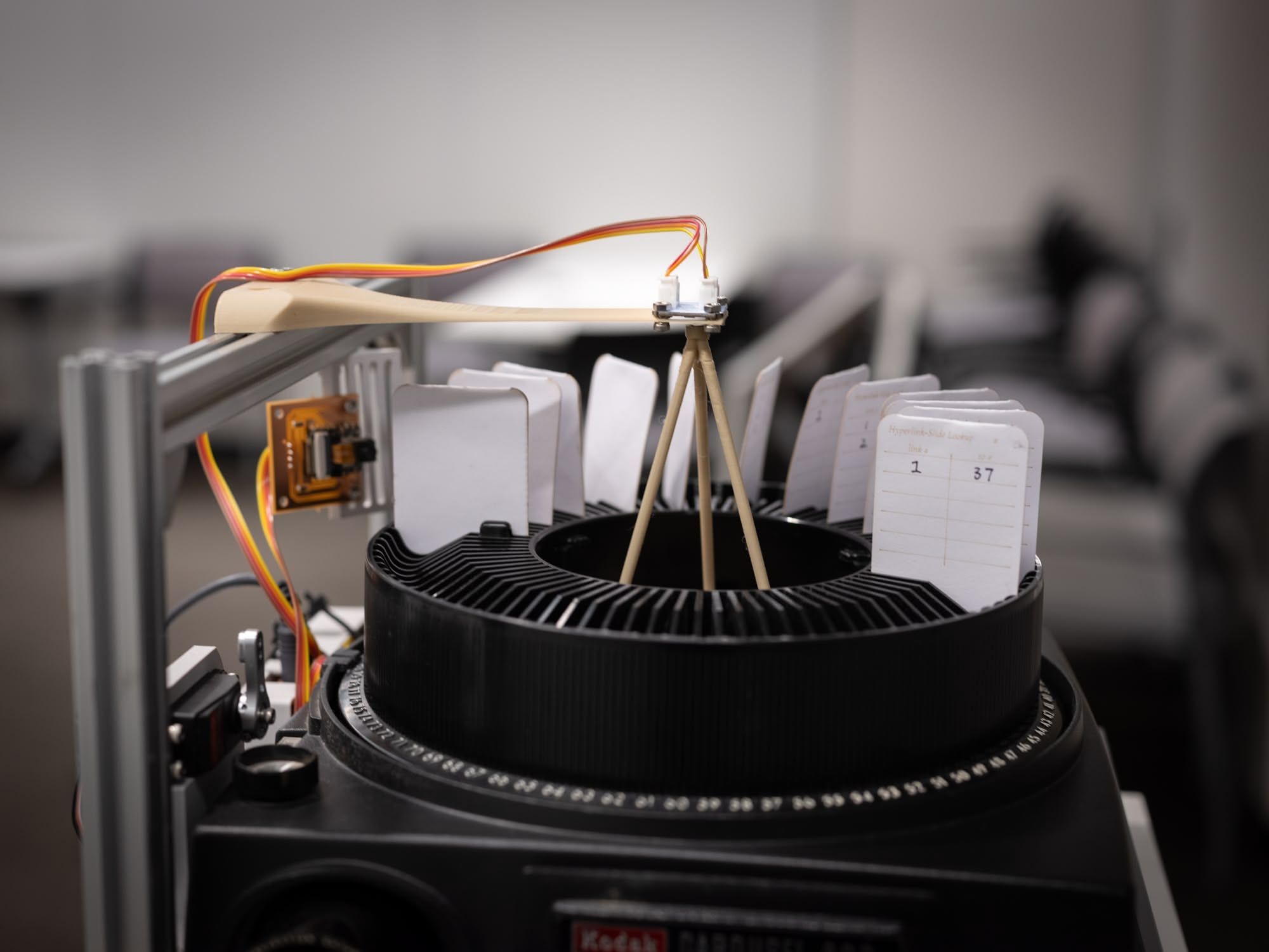
Here's the full batch of assembled HyperSlides — V4 transparencies mounted on V2 cardstock mounts, with the lookup tables filled in by hand:
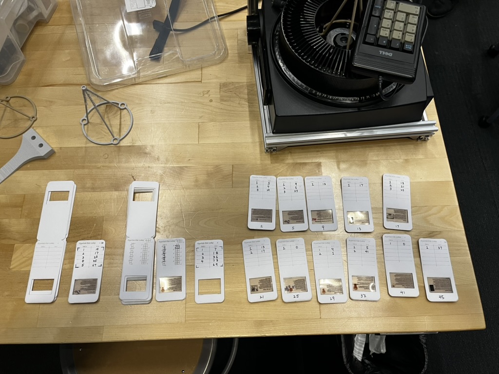
The slide numbers (1, 5, 9, 13, 17, 21, 25, 29, 33, 37, 41, 45) aren't sequential — there's a 3-slot gap between each slide on the carousel tray. This spacing ensures the camera module has a clear, unobstructed view of the lookup table when a slide is ejected. Without the gap, the adjacent slides would block the camera's line of sight.
The workflow: print transparencies -> laser cut mounts -> glue film to cardstock -> write lookup table by hand. Not elegant, but it works. Each slide's lookup table maps superscript numbers (1–9) to destination slide numbers.
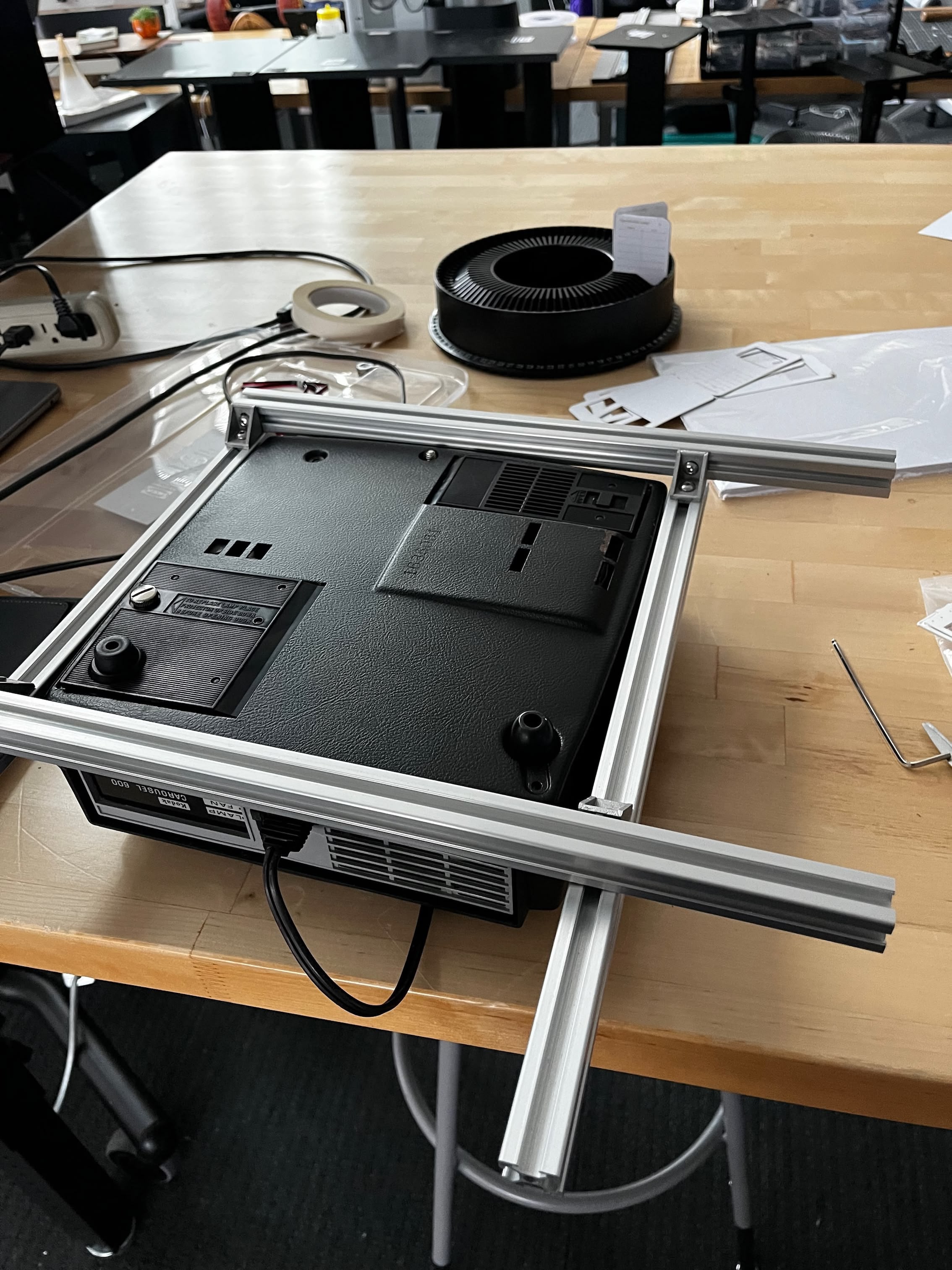
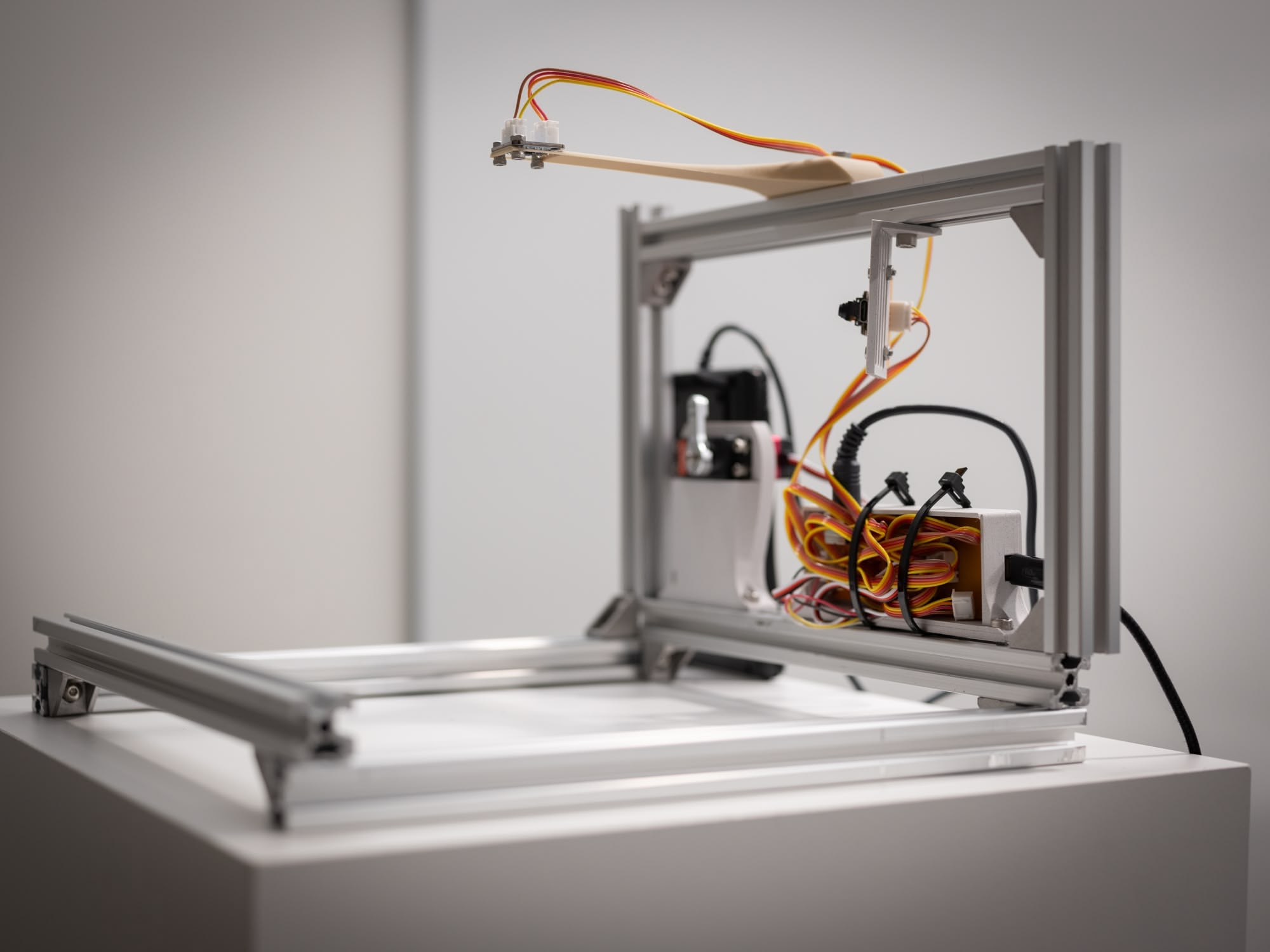
Aluminum Frame
I started with 2020 aluminum extrusions because they're cheap, easy to work with, and infinitely reconfigurable. Perfect for a prototype where I didn't know final dimensions yet.
I arranged four pieces in a square: the front and back rails sit at the bottom, while the left and right rails are raised higher. This creates a cradle that locks the projector in place from all sides.
Here's the lucky part: the Kodak Carousel 600 fits perfectly in a 276×276mm square. Like, suspiciously perfectly. No shimming, no adjustment. You can lift the whole assembly by the frame without the projector falling out — the fit is that snug.
What started as a "quick test jig" ended up being good enough for the final presentation. I never upgraded to anything fancier. Why fix what isn't broken?
The extrusions I had were longer than needed, so I trimmed each one to length with a bandsaw:
Button Pressor Servo
Remember the Geneva mechanism from my Week 9 roadmap? The precision-machined drive that would elegantly advance the carousel? Yeah, I gave up on that.
The Kodak Carousel already has physical buttons for advancing slides forward and backward. Rather than reverse-engineering the electronics or building custom mechanics, I decided to just... press the buttons with a servo. A robot finger. It's ridiculous. It's also exactly what I needed.
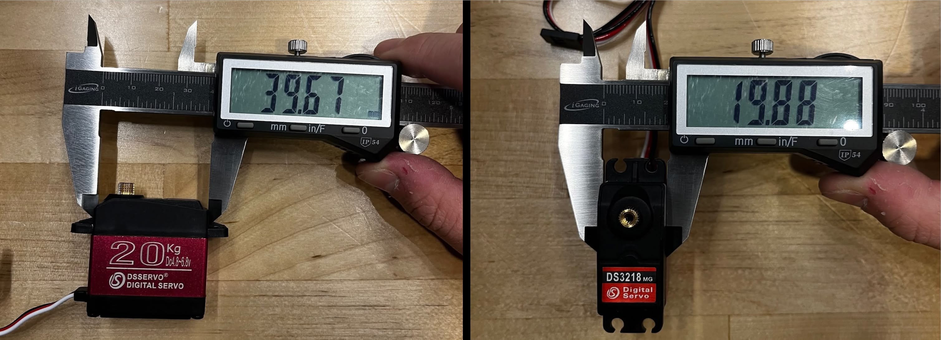
The servo I'm using is an ANNIMOS 20KG Digital Servo — high torque, full metal gear, waterproof. Wildly overkill for pressing a button that requires maybe 200g of force, but I had it lying around from a previous project.
V0: Initial Design
First step: measure the servo. The body (not including the mounting wings) is 39.67mm × 19.88mm. The mounting screws are M3, so I'm using 3.4mm holes for clearance.
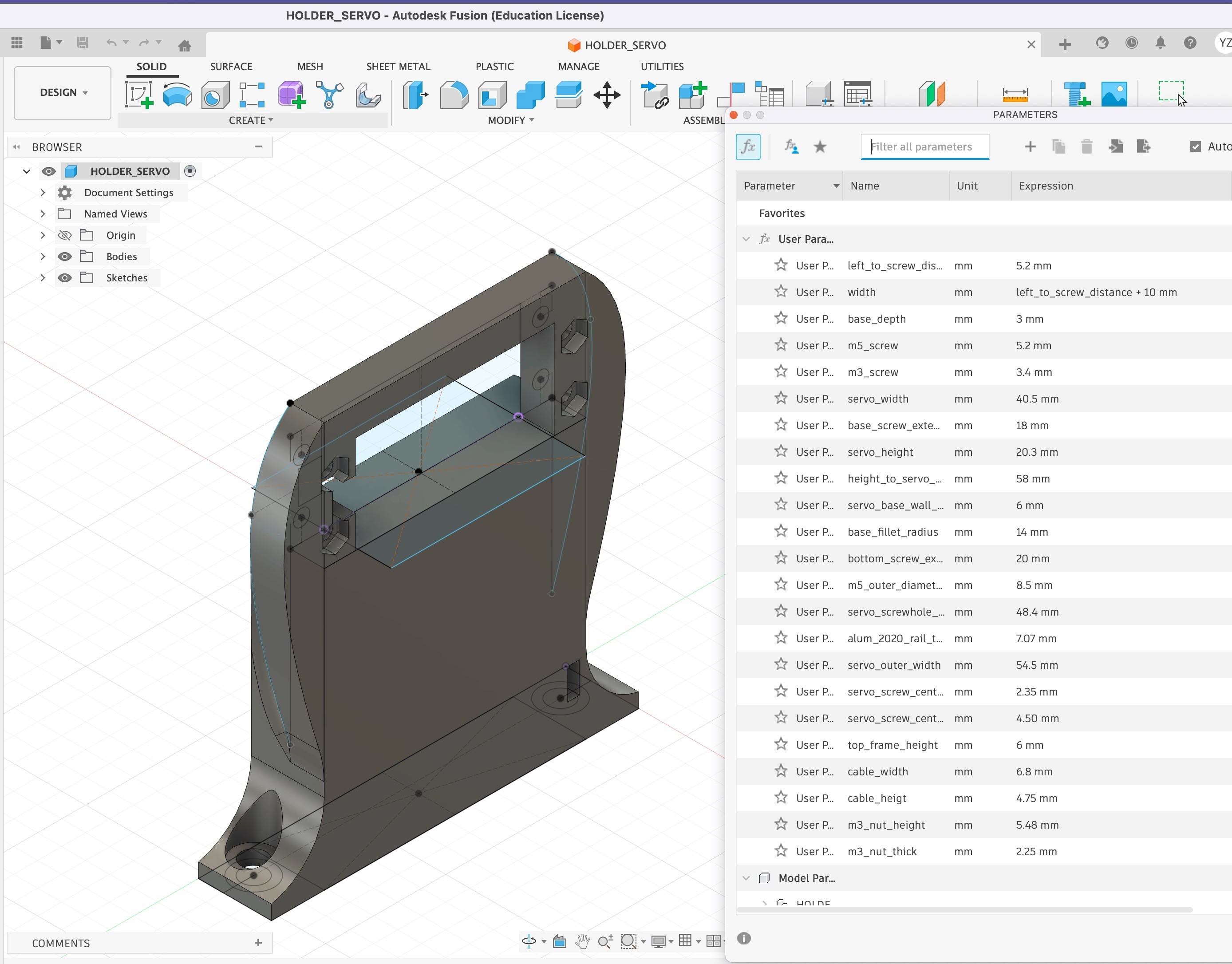
I modeled everything parametrically in Fusion 360 using 40 × 20mm as the nominal dimensions. The bottom is shaped to sit on top of the extrusion while leaving clearance for the projector body (which sticks out a bit on the sides).
Printed it, tried to install it, and immediately realized I forgot to add a notch for the cable coming out from the motor. Classic. Back to Fusion 360...
V1: Cable Notch
Added the notch for the cable, plus some curves on the edges hoping it would make them thicker for better structural integrity.
It works great, but I think it would look nicer if the model had recesses where the M3 nuts go.
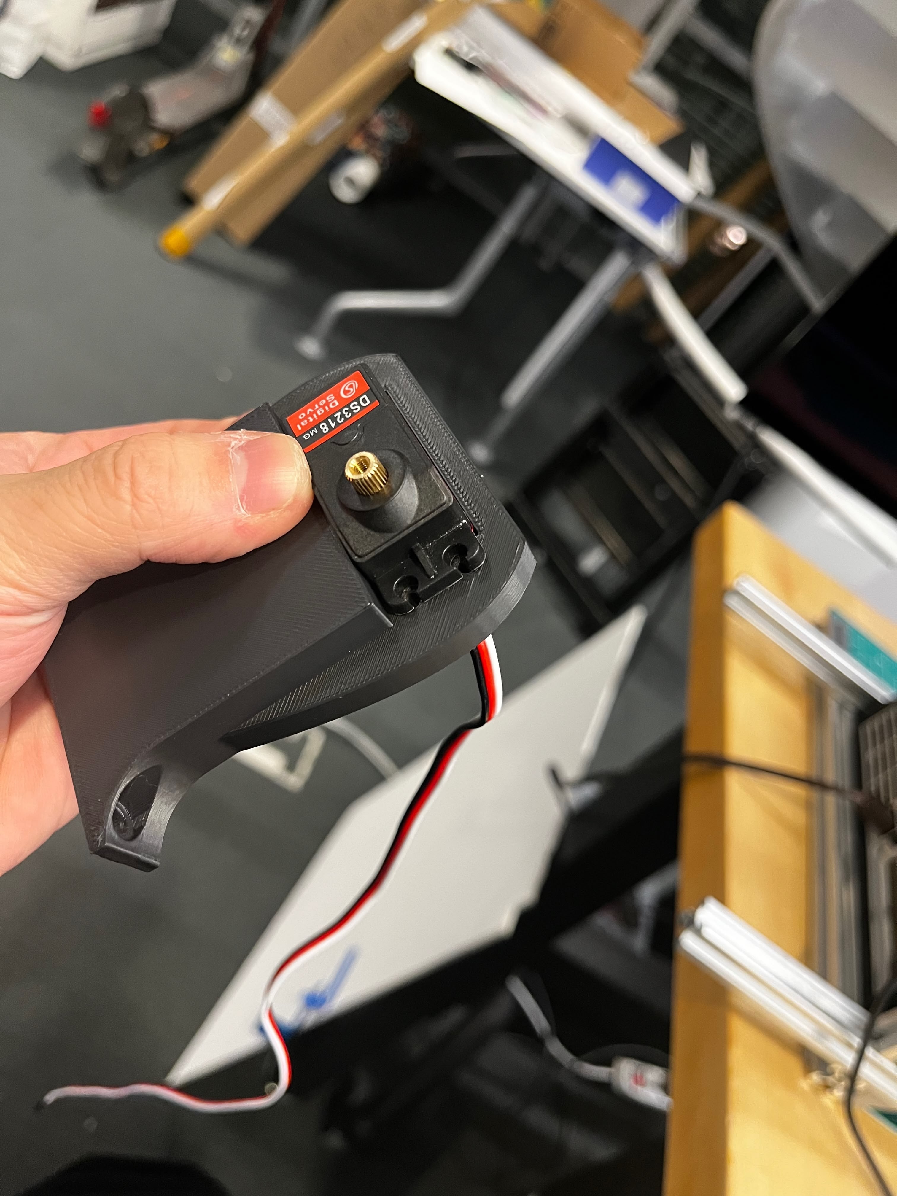
V2: Nut Recesses
Added hexagonal pockets for the nuts to sit flush. All the dimensions are parameterized in the Fusion 360 file so they're easy to tweak.
The previous prints were black PLA. For the final version, I switched to OVERTURE Rock PLA Marble filament — it has mixed particles that give a white pebble stone texture. Bonus: it hides layer lines really well.
Download V2 STL | Download Fusion 360 file
Software Test
Before integrating with the main board, I wrote a standalone test program to verify the servo works. It runs on an ESP32 (XIAO ESP32-S3) and serves a web interface for controlling the servo — useful for finding the right angles without recompiling. I tested this on the MLDEV WiFi network at Media Lab.
The code sets up a simple web server with two main features: a slider for direct angle control, and a sequence player that can run through a list of angles with configurable delays between each step. The sequence format is just angle,delay_ms per line, which made it easy to test different button-pressing motions.
Key configuration — the servo rests at 120° and swings down to 0° to press the button:
// Servo positions and speed
#define RESTING_POSITION 120    // Resting position (degrees)
#define ACTIVATION_POSITION 0   // Activation position (degrees)
#define SERVO_SPEED_MS 800      // Time to move from 0 to 120 degrees (ms)
#define SERVO_MS_PER_DEGREE (SERVO_SPEED_MS / 120.0)  // ~6.67ms per degree
The sequence execution runs in the main loop, checking if enough time has passed before moving to the next step:
// Handle sequence execution
if (sequenceRunning && stepCount > 0) {
  unsigned long now = millis();
  if (now - lastSequenceTime >= steps[sequenceIndex].delayMs) {
    sequenceIndex++;
    if (sequenceIndex >= stepCount) {
      // Sequence complete
      sequenceRunning = false;
      sequenceIndex = 0;
    } else {
      // Execute next step
      myServo.write(steps[sequenceIndex].angle);
      currentAngle = steps[sequenceIndex].angle;
      lastSequenceTime = now;
    }
  }
}
You'll notice some weird text in the web interface — I vibe-coded the frontend with emoji labels, but the ESP32's web server doesn't handle UTF-8 emoji correctly. The interface looks broken but functions fine. Good enough for testing.
Circuit Design
The system architecture connects everything through an I2C bus using JST-XH 4-pin connectors. This design extends what I built in Week 12, but with a few critical additions — and a few critical headaches I didn't anticipate.
PS/2 Daughter Board
The PS/2 numpad submodule is exactly what I built in Week 12. I didn't change a single line of code — it just worked. This is the only part of the project where something I built earlier dropped in without modification. Small victories.
The submodule has its own ESP32-C3 that reads PS/2 keystrokes and exposes them over I2C at address 0x08. The main board polls it periodically to check for new keypresses.
The 5V vs 3.3V Problem
I ran into a voltage conflict I should have anticipated earlier. Most of my peripherals — the PS/2 numpad submodule and the ESP32S3 camera — run happily on 5V I2C. But the Hall effect rotary encoder requires 3.3V. Mixing voltages on I2C is asking for trouble.
The solution: two separate I2C connector types with different power rails. Same SDA/SCL lines from the ESP32S3, but different JST connectors supplying different VCC voltages.
Connector Type | VCC | Pull-up | Connected Devices |
|---|---|---|---|
5V I2C (×4) | 5V | 4.99kΩ | PS/2 submodule, Camera ESP32S3 |
3.3V I2C (×1) | 3.3V | 4.99kΩ | Hall effect sensor |
I don't actually need four 5V I2C connectors — I only have two devices on that bus. But my Week 12 main board design already had four, and more connectors means more flexibility for future expansion. No reason to remove them.
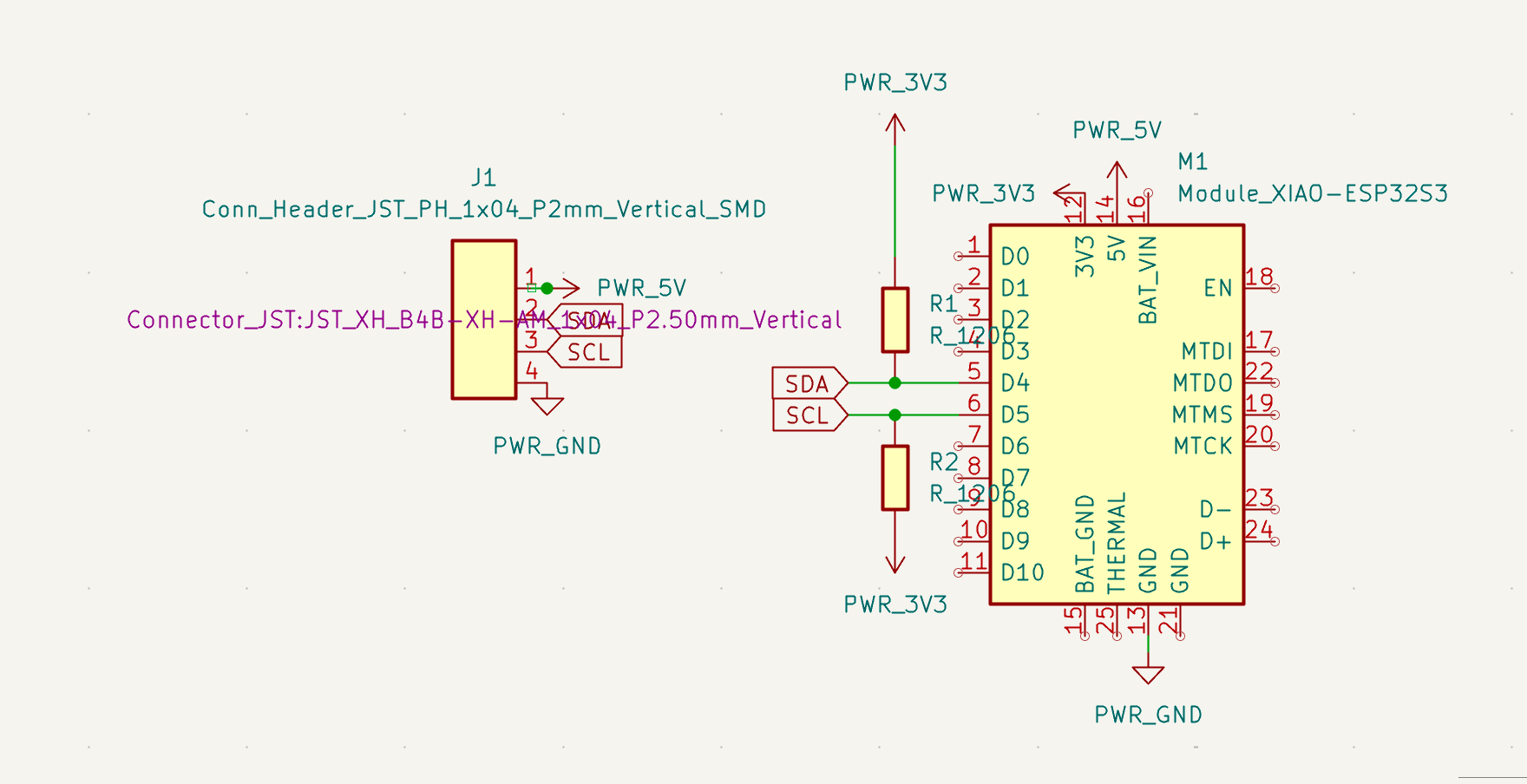
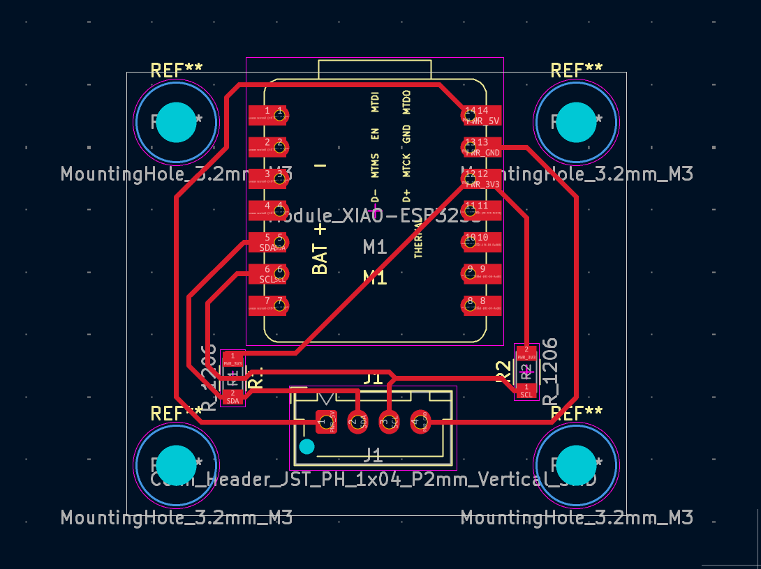
Main Board Design
The main board is built around a XIAO ESP32S3 and includes:
- 4× 5V 4-pin JST-XH I2C connectors — standard I2C with 5V power for most peripherals
- 1× 3.3V 4-pin JST-XH I2C connector — dedicated bus for the Hall effect sensor
- 1× 3-pin servo connector — PWM signal on a GPIO pin, plus 5V and GND
- 1× bistable switch — connected to a digital GPIO and ground, for mode selection
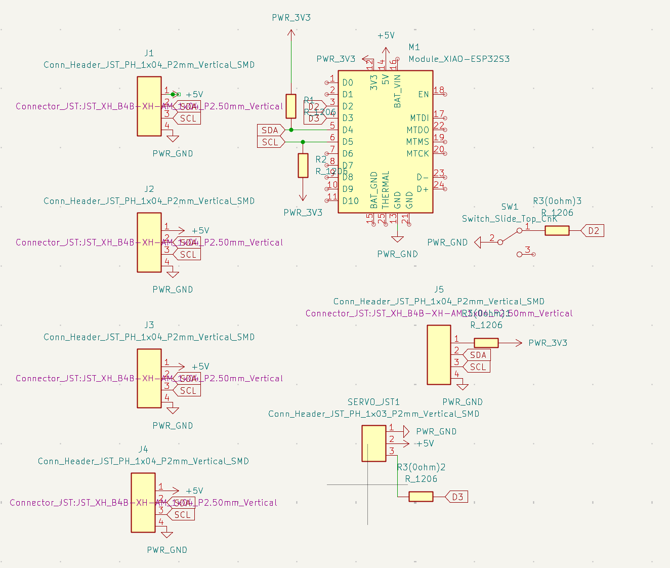
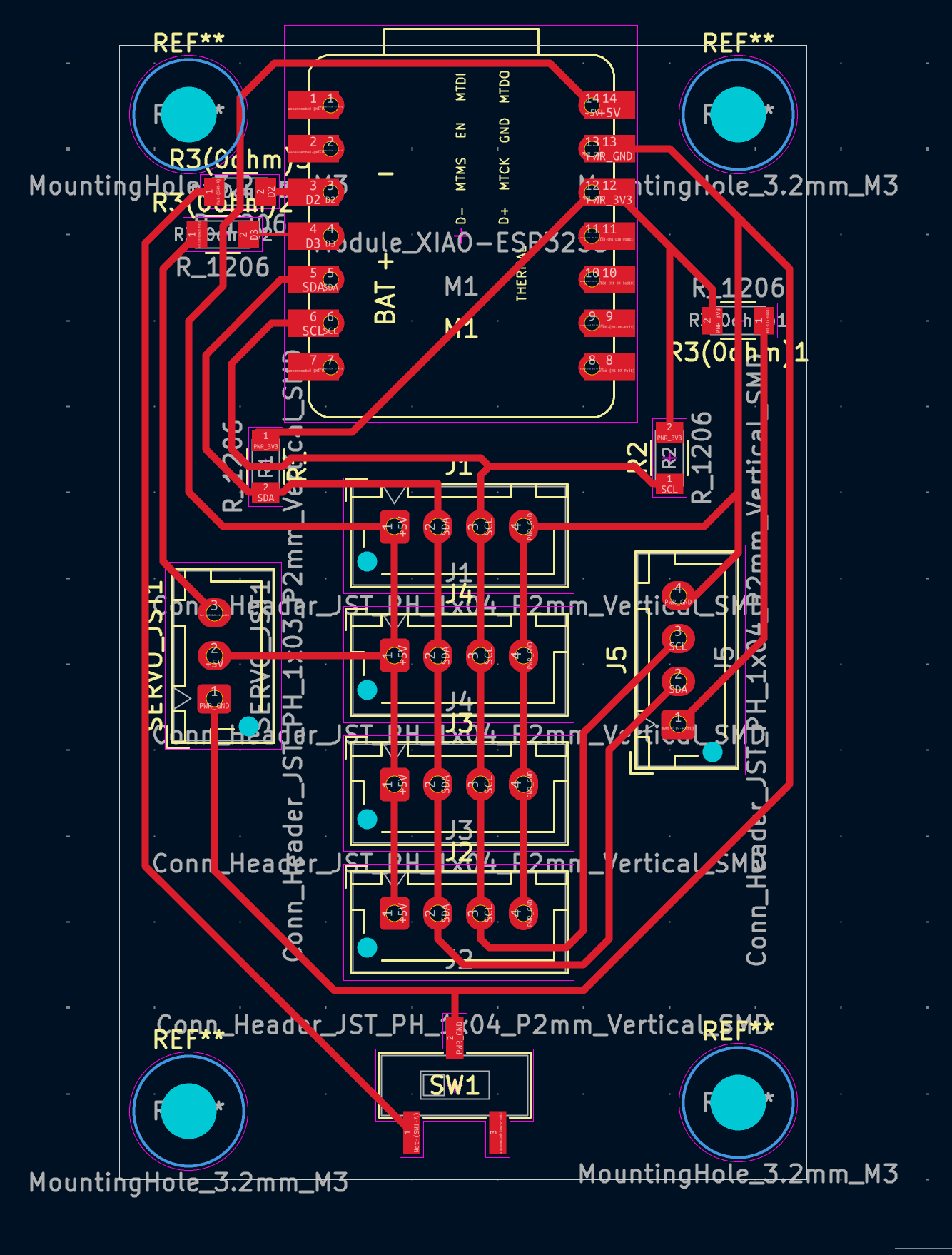
The pull-up resistors are 4.99kΩ on both buses, which is a reasonable middle ground for the cable lengths I'm dealing with (under 30cm for most connections).
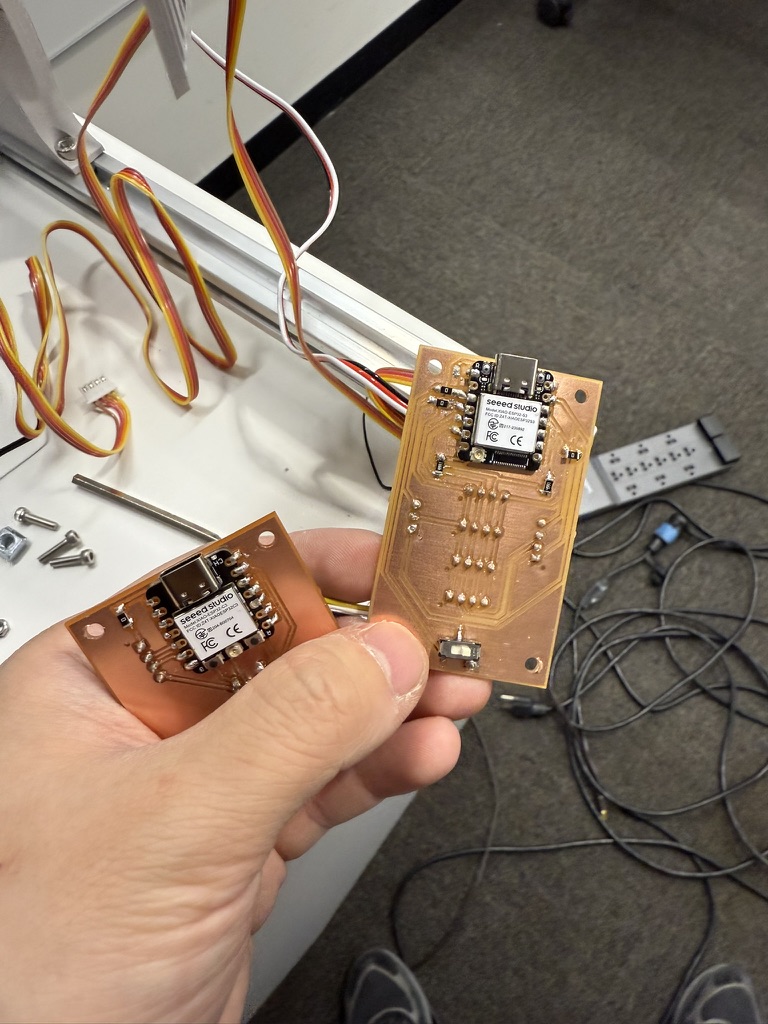
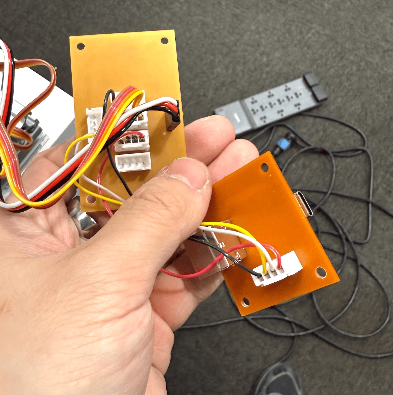
Here's the assembled PS/2 board and main board together.
Camera Module
For the camera, I'm using an ESP32S3 Sense — the variant that comes with a detachable OV2640 camera module. This board also sits on the I2C bus for communication with the main controller, though the actual image processing happens on-board. I designed a simple breakout board for it:
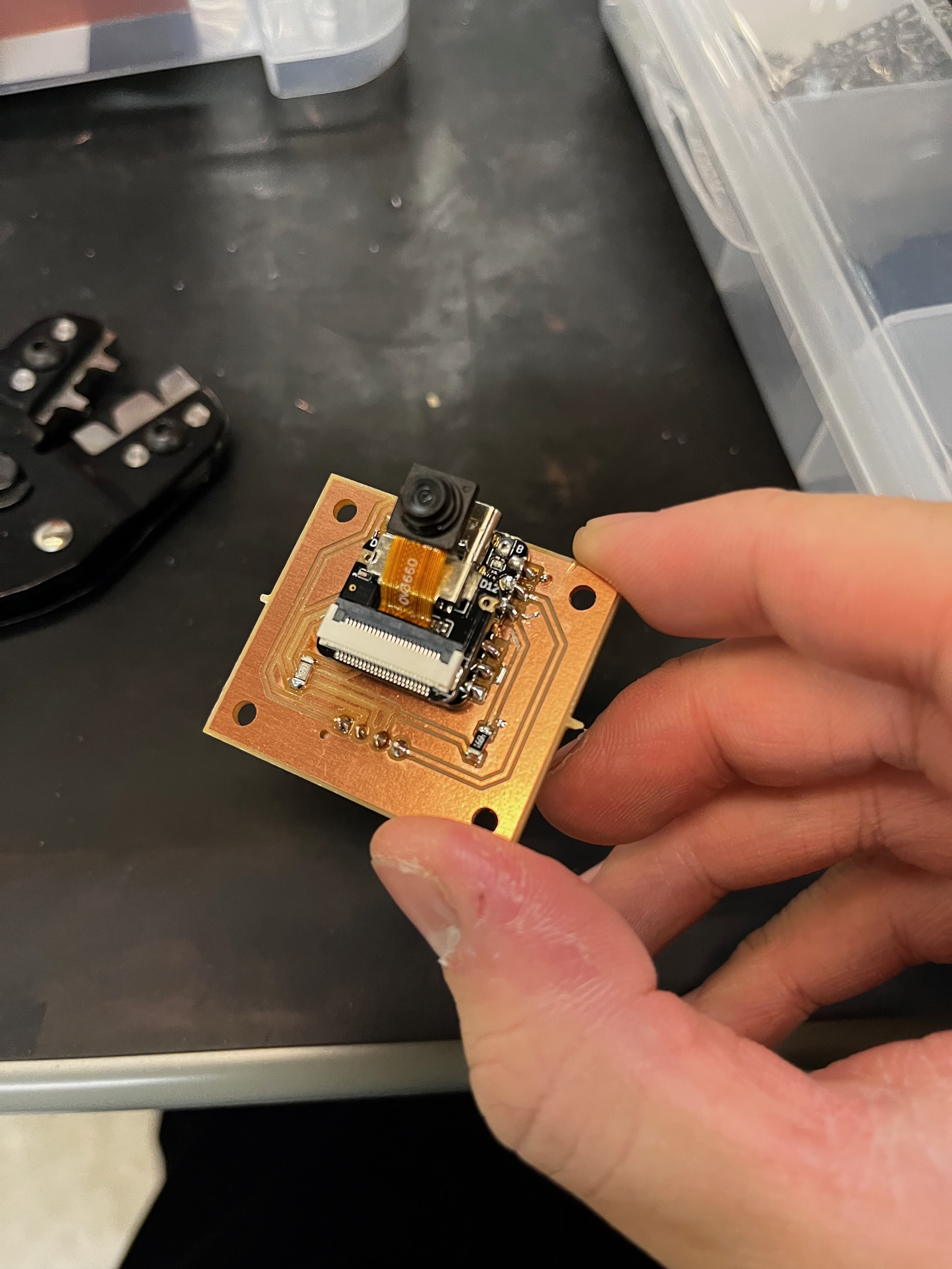
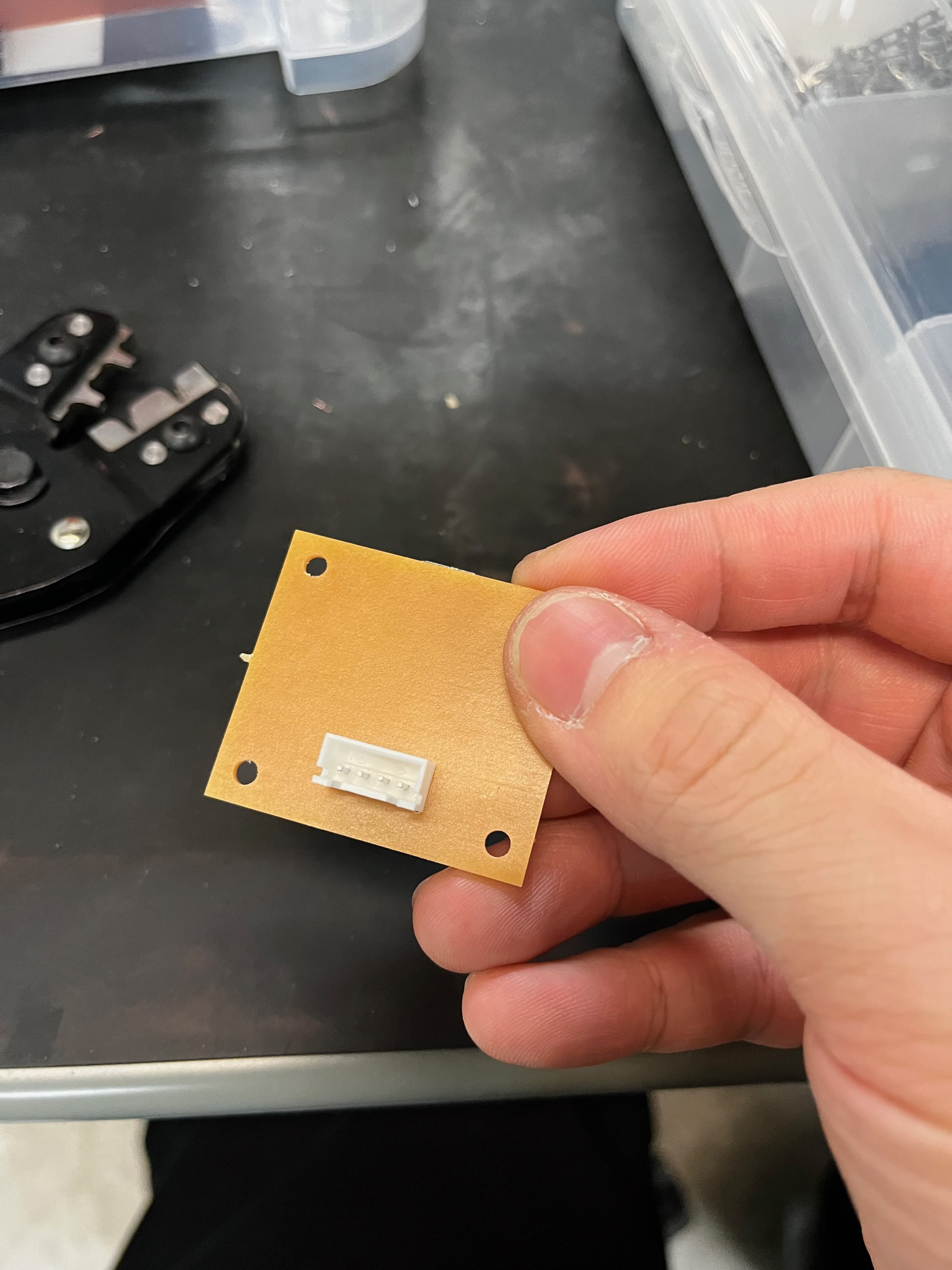
More on the camera software in the Lookup Table Recognition section.
Lookup Table Recognition
This is where the project gets ambitious — and where I'm still struggling.
The whole point of the HyperSlide design is that each slide mount has a handwritten lookup table mapping hyperlink numbers to destination slide numbers. The camera's job is to read this table when a slide is ejected. Simple in theory. Turns out handwriting recognition on a microcontroller with a cheap camera is... not simple.
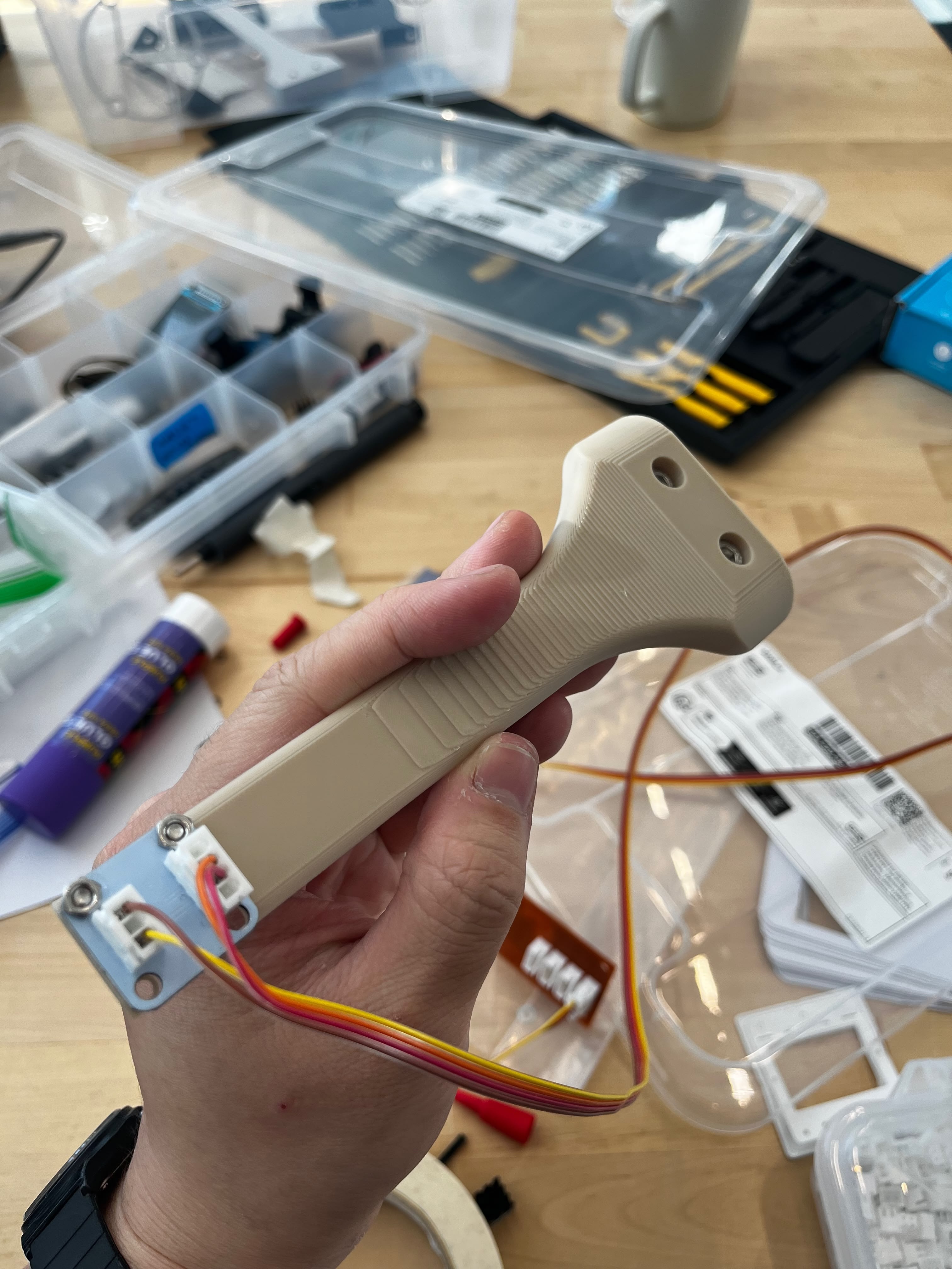
Camera Holder Design
The 3D printed holder has elongated M3 screw slots instead of fixed holes. This lets me slide the camera up and down to find the optimal height and viewing angle before tightening the screws. Small adjustment range, but it makes a huge difference when trying to get consistent framing.
Download V1 STL · Download V2 STL · Fusion 360 Source
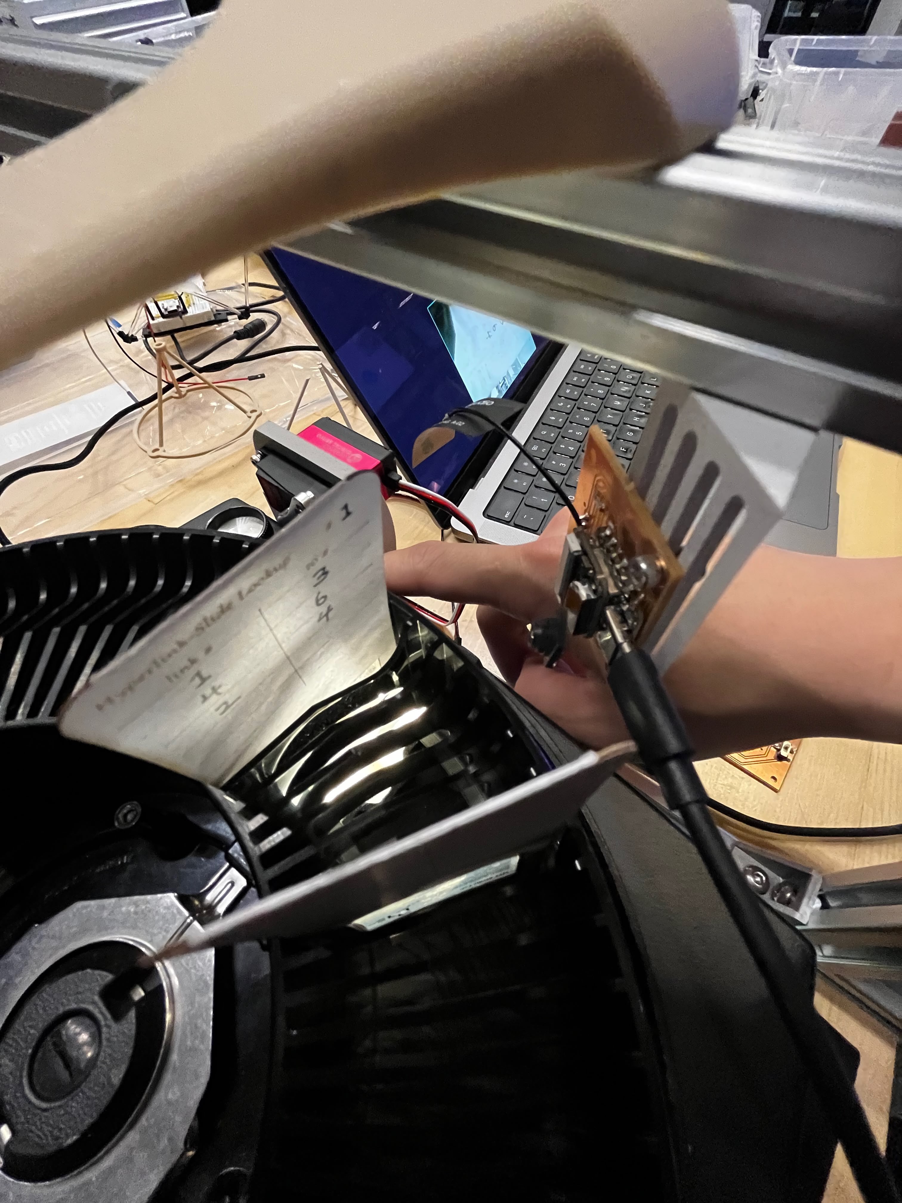
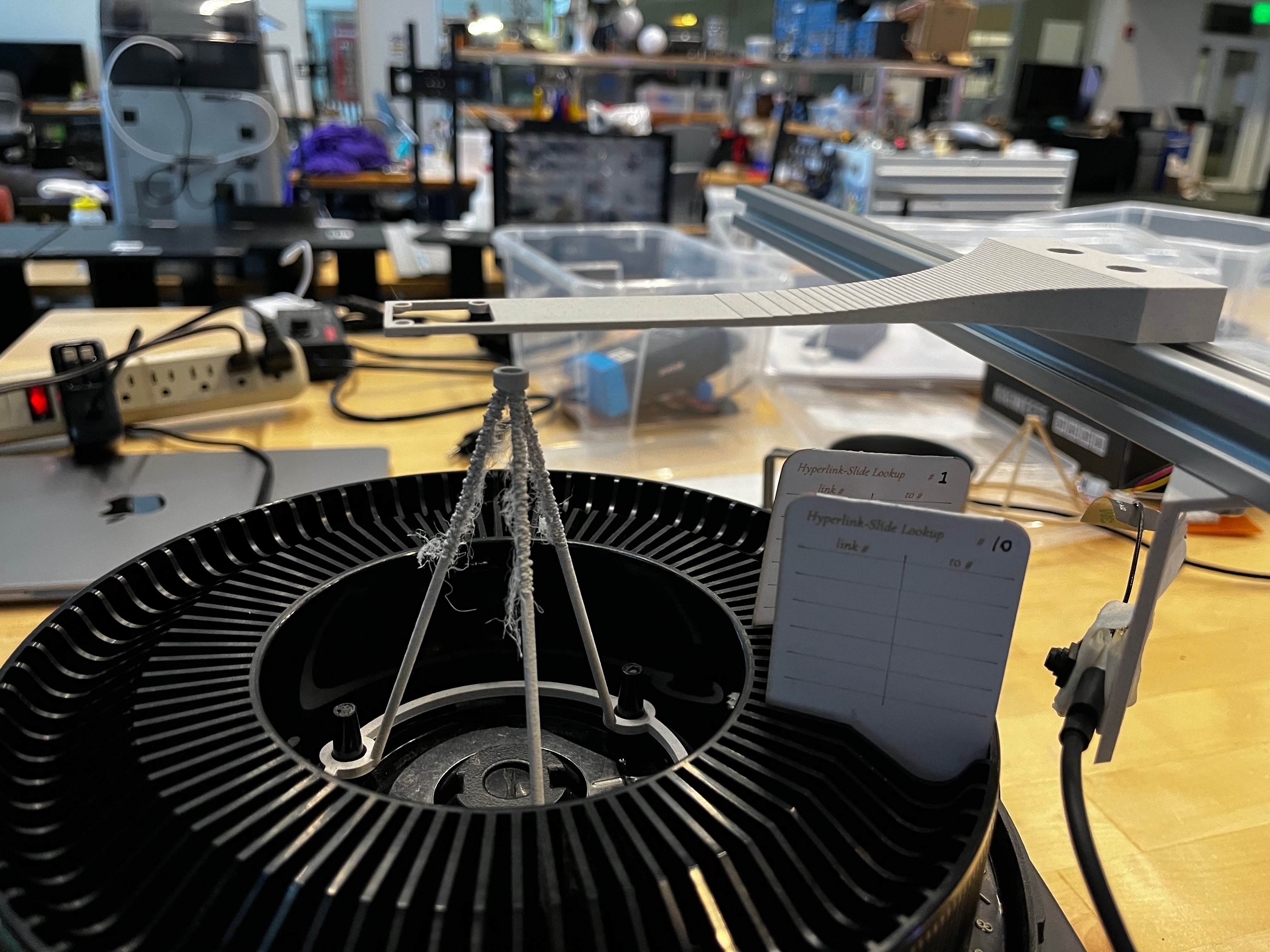
Camera Mounting
I added a new vertical aluminum extrusion bar to the frame specifically for the camera. The bar sits perpendicular to the projector's slide ejection slot, giving the camera a top-down view of the slide mount.
The CV Pipeline
I wrote the entire computer vision pipeline from scratch in C++ on the ESP32S3, without OpenCV (too heavy for embedded). The recognition pipeline has five stages:
Step 1: Crop — Remove unnecessary borders to focus on the card area. I crop 20% from top, 21% from bottom, and 19% from left.
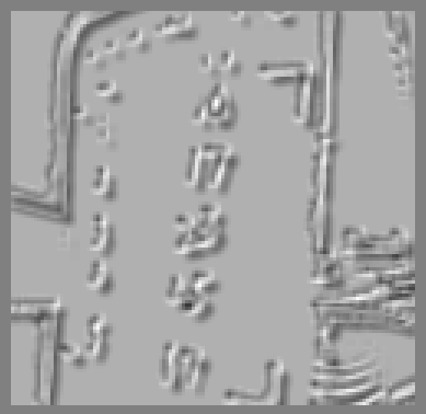
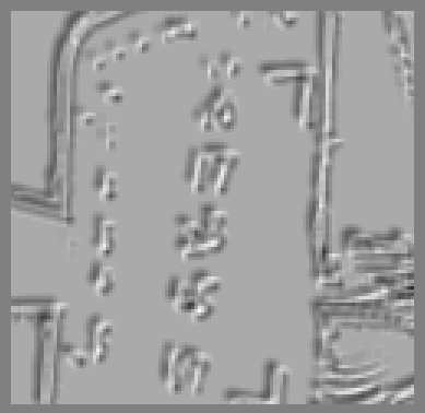
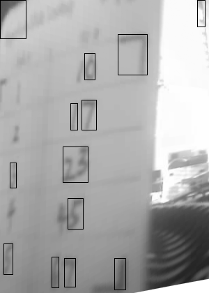
Step 2: Binary threshold — Adaptive thresholding converts grayscale to binary (block size 35px, constant C=10).
Step 3: L-mark detection — This is the key innovation. Instead of generic quad detection, I designed L-shaped corner markers for each corner of the lookup table. Each L-mark has a specific orientation, and I use convolution kernels to detect them:
// L-mark detection — check corner darkness, measure arm lengths, score by balance
inline float scoreLMark(const GrayImage& img, int cx, int cy, LMarkType type, ...) {
    int hDir, vDir;  // direction vectors based on L-mark orientation (TL/TR/BL/BR)
    // ... measure horizontal and vertical arm lengths from corner point ...
    if (hLen < minArm || vLen < minArm) return 0;
    float ratio = (float)std::min(hLen, vLen) / std::max(hLen, vLen);
    return ((hLen + vLen) / 2.0f) * (0.5f + 0.5f * ratio);  // favor balanced arms
}

Step 4: Perspective transform — Apply homography to warp the detected quad to a 300×420 rectangle.
Step 5: Digit recognition — Find connected components, filter by size, group into rows, and classify using heuristic features (aspect ratio, density, vertical distribution).
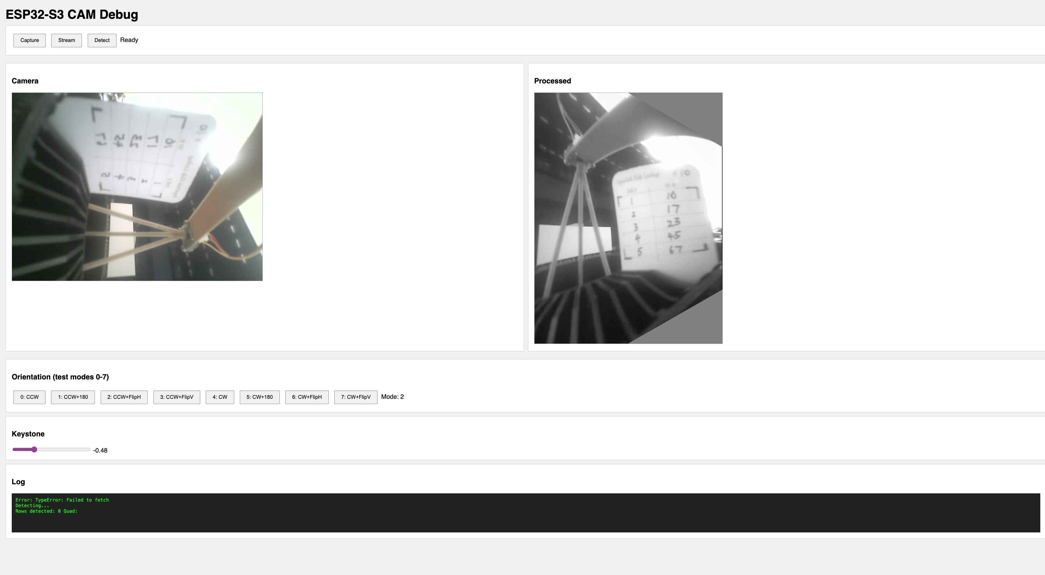
Web Debug Interface
I built a web interface served directly from the ESP32S3 to preview the camera feed and test the pipeline in real-time. The interface includes orientation controls (8 rotation/flip combinations) and a keystone correction slider — useful for dialing in the camera position without recompiling.
Cloud OCR via Vercel
The on-device heuristic recognizer works for clean images, but struggles with real-world handwriting variation. So I also built a cloud fallback — the ESP32S3 sends the processed image to a Vercel serverless function that calls Google Cloud Vision API:
// Cloud OCR - captures, transforms, and sends to Vercel API
inline CloudOCRResult captureAndOCR() {
    CloudOCRResult result;

    // Capture and decode to grayscale
    camera_fb_t *fb = esp_camera_fb_get();
    // ... decode JPEG to grayscale ...

    // Apply transforms: 90° CCW rotation + horizontal flip
    GrayImage rotated, flipped;
    rotate90CCW(original, rotated);
    flipH(rotated, flipped);

    // Enhance contrast for better OCR
    enhanceForOCR(flipped);

    // Encode back to JPEG and send to Vercel
    uint8_t *jpegBuf = grayToJpeg(flipped, &jpegLen, 95);
    result = cloudOCR(jpegBuf, jpegLen);  // HTTP POST to Vercel

    return result;
}
The Vercel endpoint extracts numbers from the right column of the lookup table:
// Vercel API route - /api/ocr
import vision from "@google-cloud/vision";

export async function POST(request: Request) {
  const { image } = await request.json();
  const client = new vision.ImageAnnotatorClient();

  const [result] = await client.textDetection({
    image: { content: image },
  });

  // Extract numbers from right column based on x-position
  const numbers = result.textAnnotations
    ?.filter((a) => /^\d+$/.test(a.description || ""))
    .filter((a) => a.boundingPoly?.vertices?.[0]?.x > imageWidth * 0.6)
    .sort((a, b) => a.boundingPoly.vertices[0].y - b.boundingPoly.vertices[0].y)
    .map((a) => parseInt(a.description));

  return Response.json({ numbers, success: numbers.length > 0 });
}
The Reality (It Doesn't Work Well)
Let me be honest: the recognition accuracy is bad.
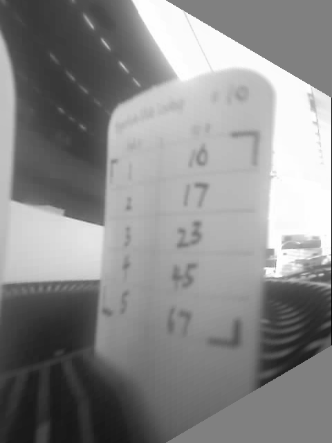
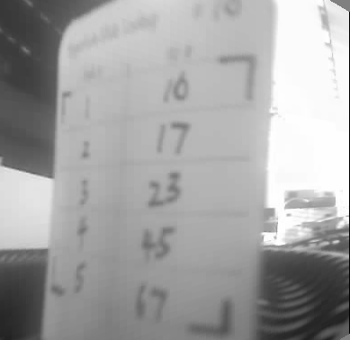
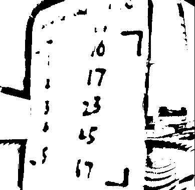
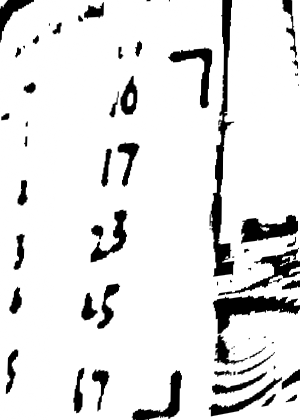
On-device heuristic recognizer — Results from the test image: 17, 17, 6, 5, 74 — but the ground truth was 16, 17, 23, 45, 67. Only row 2 was correct. That's 20% accuracy.
Row | Detected | Expected | Issue |
|---|---|---|---|
1 | 17 | 16 | Misclassified 6 as 7 |
2 | 17 | 17 | Recognized |
3 | 6 | 23 | Digits merged together |
4 | 5 | 45 | Missing first digit |
5 | 74 | 67 | Misclassified |
Merged digits are the main killer. When handwritten digits like "23" touch in the binary image, they're detected as a single blob. The heuristic recognizer can't handle that.
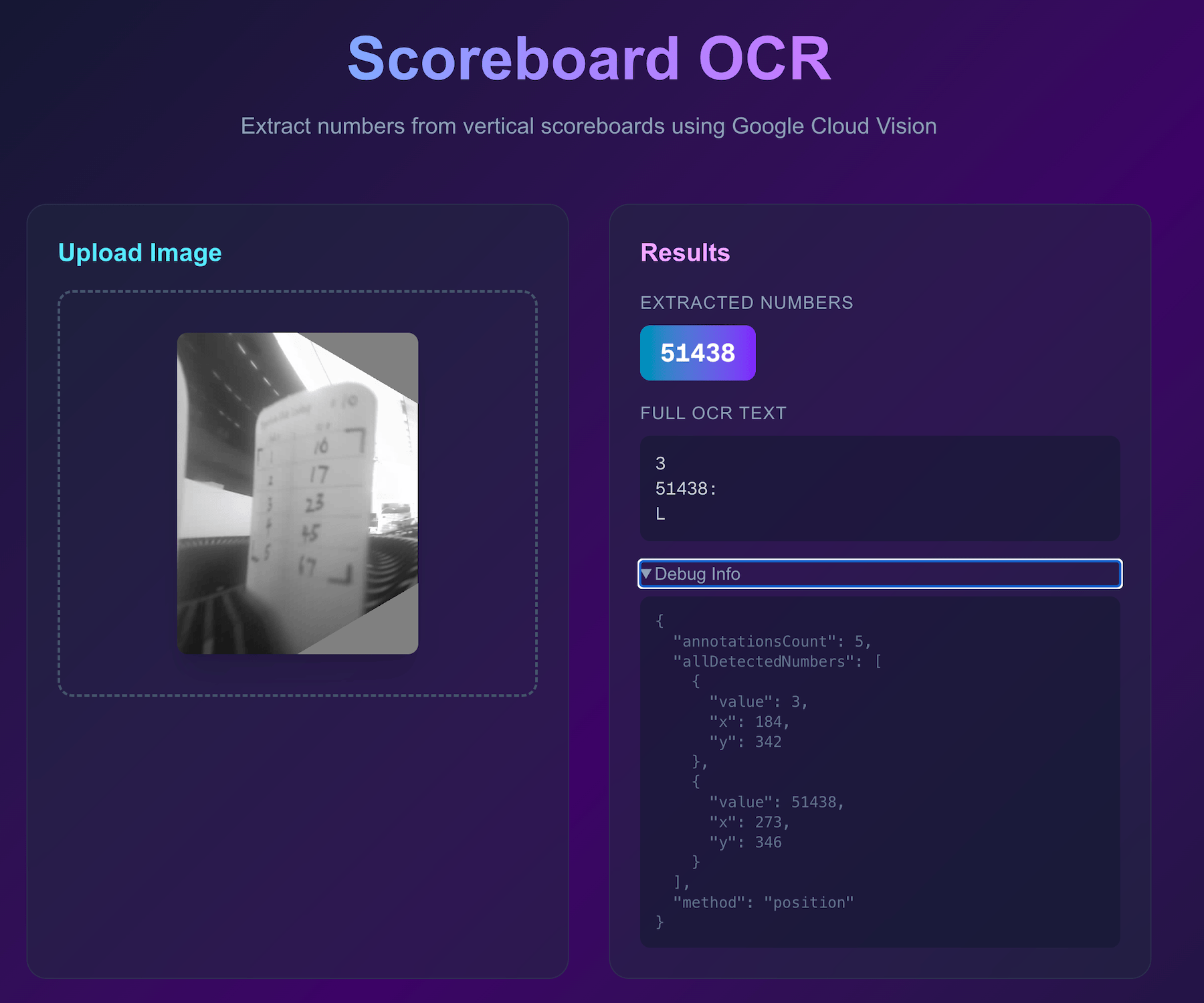
Google Cloud Vision API — I thought the cloud would save me. It didn't. The API concatenates all visible digits into a single number "51438" instead of parsing them row by row. It detected characters fine but couldn't understand the table structure. The low resolution (480×640 after rotation) probably doesn't help — Google Vision is optimized for document scans, not tiny cardstock tables photographed by a $3 camera module.
I tried the V3 HyperSlide design with seven-segment digit guides scored into the cardstock. The idea was to help users write consistent, recognizable digits. But the laser scoring created too much contrast — the dark score lines confused the CV algorithm more than the handwritten digits themselves. My "fix" made things worse.
What I Think I Need (Future Work)
- Higher resolution camera — the OV2640 maxes out at 2MP, which is likely insufficient for reliable OCR of small handwritten digits. A 5MP module might help.
- Morphological operations — erosion to separate touching digits before connected component analysis
- Digit splitting heuristics — detect wide blobs and attempt to split them based on aspect ratio
- Better training data — the heuristic recognizer was tuned on maybe 5 test images; it needs hundreds
This part of the project is still very much in progress. For the final demo, I pre-loaded the lookup tables into the main controller's memory and bypassed the camera entirely. Not proud of it, but it let me demonstrate the core navigation concept.
The Hardcoded Fallback
Since the OCR wasn't reliable enough, I added a hardcoded lookup table directly in the main board firmware. The system has two modes controlled by a bistable switch: Lookup Table Mode (default) uses the hardcoded table, while Camera OCR Mode queries the camera — but I never got the camera mode working reliably enough to use it in the demo.
Here's the hardcoded table structure:
// Lookup table: lookupTable[slide][numpad-1] = destination slide
// numpad 1 = index 0, numpad 2 = index 1, etc.
const uint8_t lookupTable[TOTAL_SLIDES][MAX_LOOKUP_OPTIONS] = {
    {LOOKUP_INVALID, LOOKUP_INVALID, LOOKUP_INVALID, LOOKUP_INVALID}, // 0: no slide
    {5, 9, 29, LOOKUP_INVALID},                                       // 1: 5, 9, 29
    // ... slides 2-4 have no links ...
    {9, 5, 37, LOOKUP_INVALID},                                       // 5: 9, 5, 37
    // ... etc for all 81 slides ...
};
Each slide can have up to 4 destination options (matching numpad keys 1–4). LOOKUP_INVALID (0xFF) means that numpad key has no destination for that slide. The firmware looks up lookupTable[currentSlide][numpadKey - 1] and advances to that slide number.
It's the opposite of elegant — every time I change the slide content, I have to manually update the C++ array and reflash the ESP32. But it works, and for a demo that's what matters.
Design Files
- ESP32-S3 Camera OCR Source Code (.zip) — PlatformIO project with vision pipeline, web debug interface, and Vercel cloud OCR integration
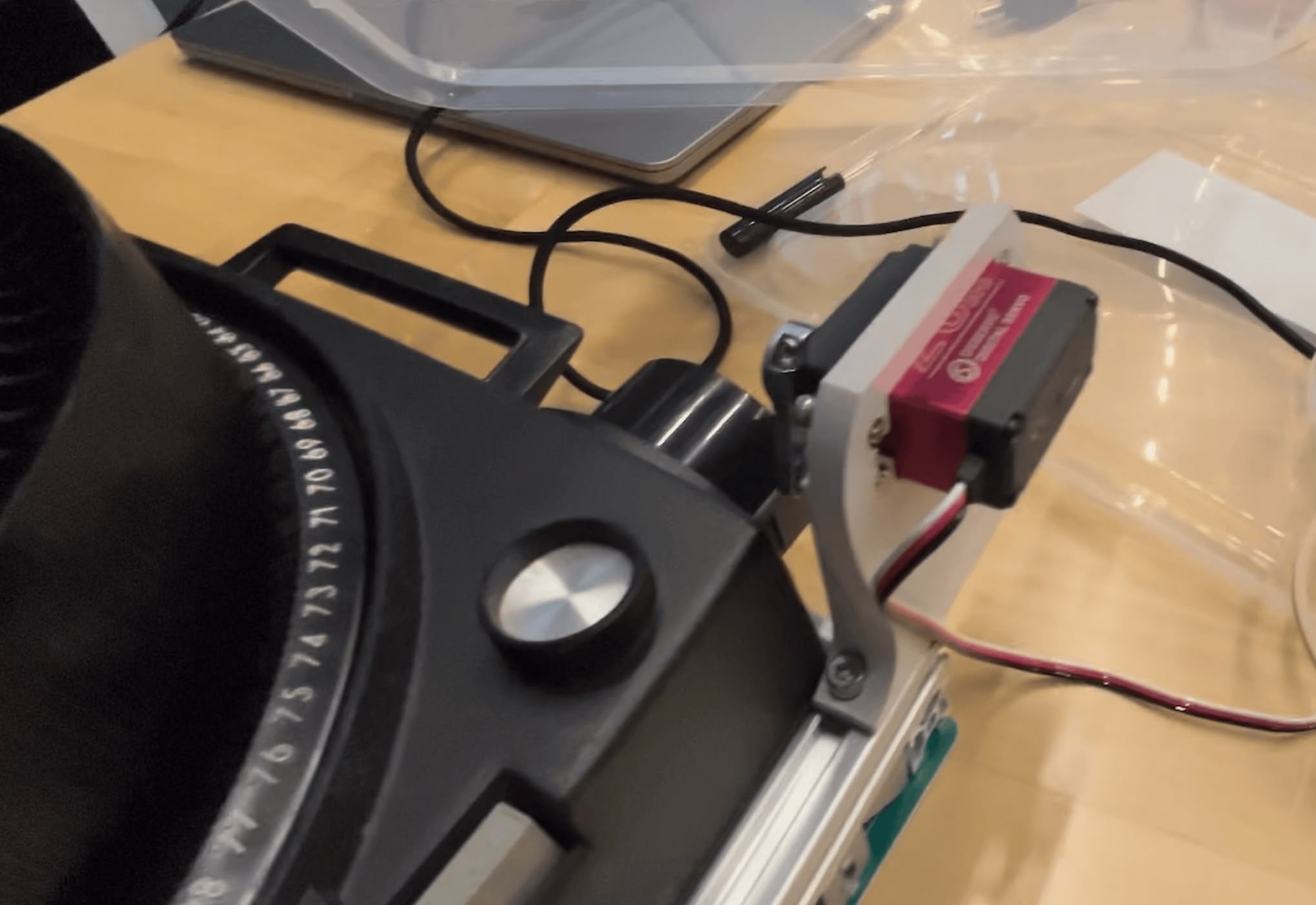
Rotary Encoder
To track which slide is currently in position, I planned to use a Hall effect sensor to detect the carousel tray rotation. This section is mostly about why it didn't work.
The Idea
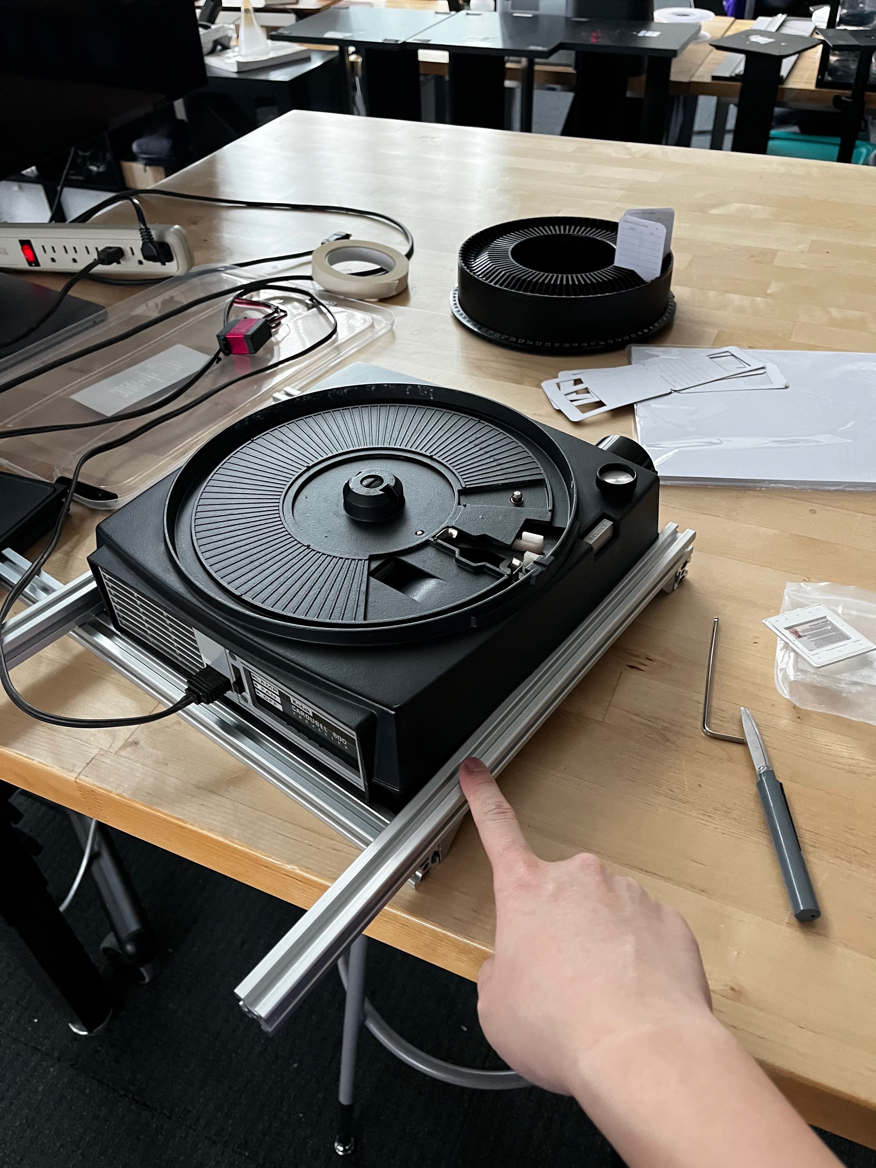
The Kodak Carousel tray has 80 slots arranged in a circle. As the tray rotates, I need to count how many slots have passed to know which slide is currently at the projection position. A Hall effect sensor can detect the metal parts of the tray mechanism as they pass by — no physical contact needed.
Sensor Mounting
I 3D printed a holder arm that extends over the carousel tray. The Hall effect sensor PCB mounts at the end, positioned about 3-4mm above the rotating tray mechanism — close enough to detect reliably, far enough to avoid physical contact.
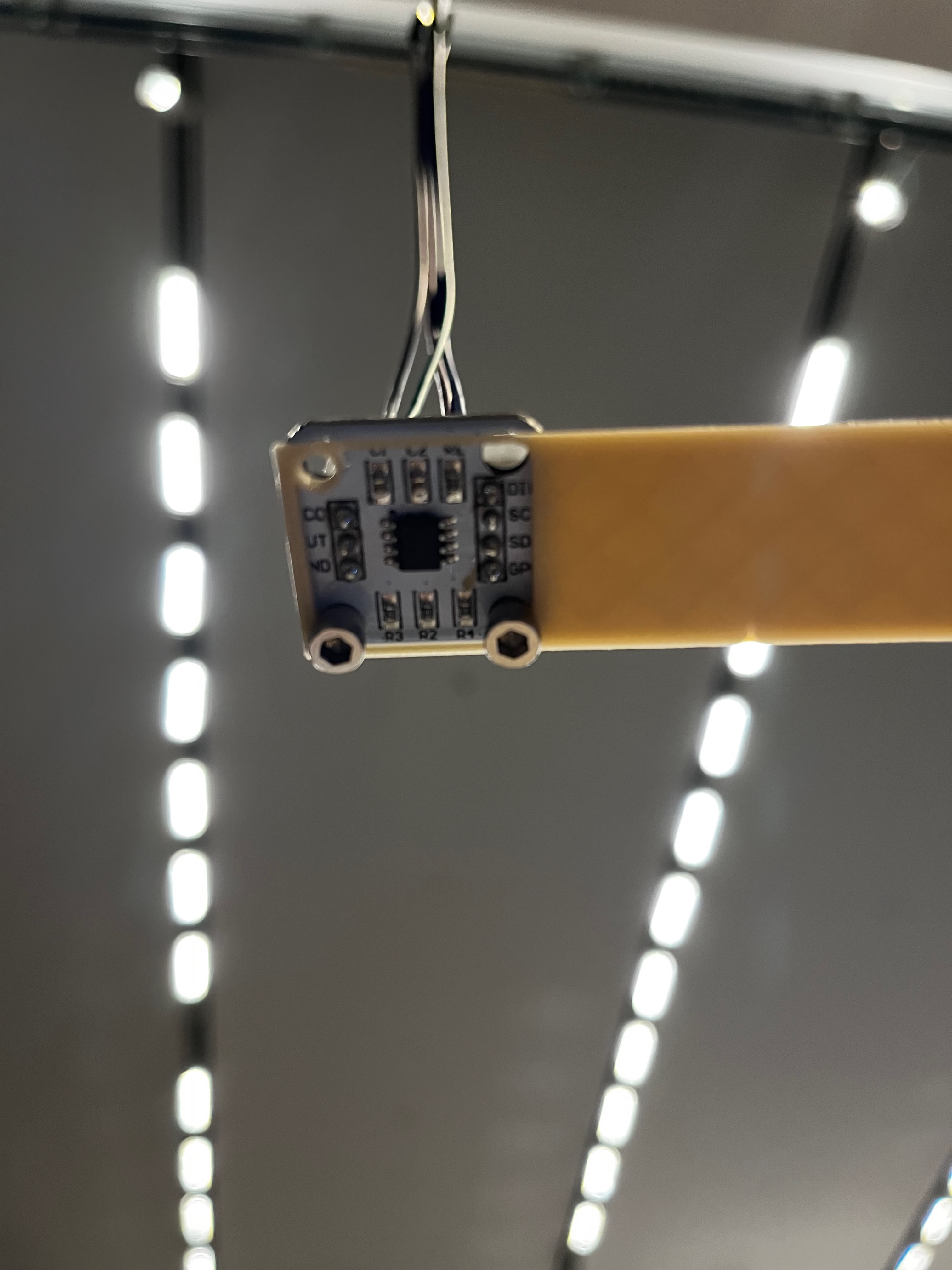
In isolated testing (just the sensor and the main ESP32S3), it works perfectly. Clean pulses, reliable detection, accurate counting. I was feeling good about this.
The I2C Problem (Why It's Currently Disabled)
Here's where things went wrong.
The Hall effect sensor (AS5600) uses I2C. I bought a pre-assembled breakout board from Amazon — convenient, but that convenience came with a catch.
When I test the sensor alone — just the AS5600 connected to the ESP32S3 — it works perfectly. Clean signals, reliable readings, no issues. But the moment I connect it alongside other I2C devices on the main board, I2C errors start appearing. Interestingly, the other I2C devices (PS/2 submodule, camera board) work fine together — the errors only happen when the Hall effect sensor is connected.
My suspicion: the breakout board probably has different I2C pull-up resistor values than what I designed for on my main board. Having mismatched pull-ups on the same bus can cause signal integrity issues. I didn't have time to investigate further — measuring the resistors, testing different values, or designing my own AS5600 breakout would have been the proper debugging path.
For the final demo, I disconnected the Hall effect sensor entirely. Instead, I rely on manual reset — every time HyperCarousel is turned on, the carousel tray has to be manually positioned to slot 0 before the system works properly. The software assumes it starts at position 0 and counts button presses from there.
For a proof of concept, this is fine. The carousel still works, just with a minor setup step. Proper position tracking remains on the list for a future revision.
Reflection
This project started as an exercise in analog nostalgia and ended as a lesson in compromise. Week 1 me wanted a purely mechanical system. Week 15 me has multiple microcontrollers, I2C buses, computer vision, and cloud API calls.
What Worked
- The servo button presser — Sometimes the dumbest solution is the right one
- The PS/2 submodule — Built once in Week 12, dropped in without changes
- The aluminum frame — A "temporary" test jig that became permanent
- The HyperSlide design — V2 works reliably after the width fix
What Didn't Work
- Cursor overlay — Killed by basic optics I should have tested first
- On-device OCR — 20% accuracy isn't good enough
- Cloud OCR — Doesn't understand table structure
- Hall effect sensor integration — I2C conflicts I can't resolve
What I Learned
The biggest lesson: test your risky assumptions first. I spent weeks planning the cursor overlay system before trying it for 30 seconds. That 30-second test could have happened on day one.
Second lesson: embrace the dumb solution. The servo pressing buttons is ridiculous. It's also the only motor system in this project that works reliably. Elegant engineering is worthless if it doesn't ship.
Third lesson: I2C is harder than it looks. Multiple devices on a bus with mixed voltages, varying speeds, and different pull-up requirements? Debugging that is a project in itself.
HyperCarousel V0 is a proof of concept that proves the concept. It navigates slides based on numpad input. The hyperlink detection mostly doesn't work, and the position tracking is disabled. But you can stand in front of it, press "3" on the numpad, and watch it advance to slide 3. That's something.
V1 will need a better camera, a rethought I2C architecture, and probably a lot more debugging. But that's for next semester.
References
- Vannevar Bush's Memex — As We May Think (1945)
- 35mm Film Dimensions — Kodak Digitizing Blog
- Aperture Cards — Wikipedia
- PS/2 Protocol — Documented in Week 12
Design Files
All source code is available at github.com/yz3440/hypercarousel-v0.
- HyperSlide Mounts
- Servo Holder
- Computer Vision
