

This week, we were to use the Instron to test a structure or mechanism, and relate the results to the material characteristics.
Casting alloy testing
I've been making a case for moving from Babbit casting up to Aluminum in fab labs and fab class. The small furnace in the fab lab inventory can easily melt aluminum, and sand molds are relatively easy to make (and much cheaper than high temperature silicone!). Below is a quick video from pouring an ingot in the CBA shop.
The lost foam process uses extremely cheap materials (building foam, sand, drywall mud) and processes available in a fab lab to produce parts (milling foam). I hope to play with this process for machine development soon.
To make the case stronger, I decided to do a material comparison between grade 3 Babbit and Aluminum 6061. Brinell scale. can convert to tensile strength.
Brinell hardness is given by $$ BHN = \frac{2F}{\pi D^2} \left(1 - \sqrt{1-\frac{d^2}{D^2}}\right)^{-1}$$ where $F$ is the applied force, $D$ is the diameter of the indenter sphere, and $d$ is the diameter of the indentation.
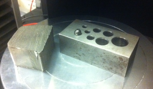
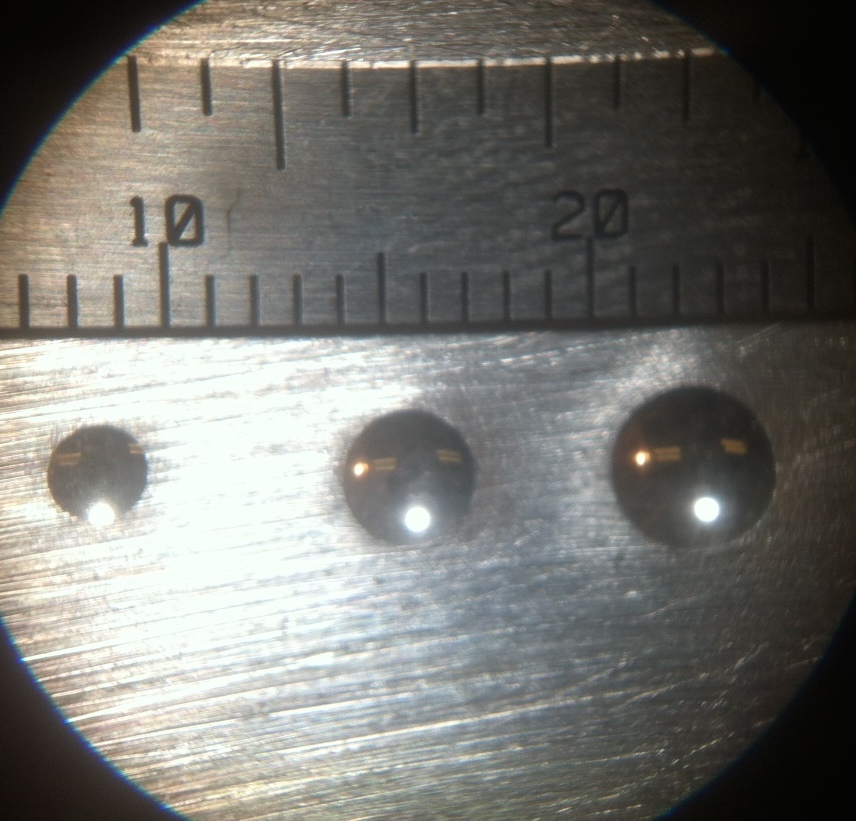
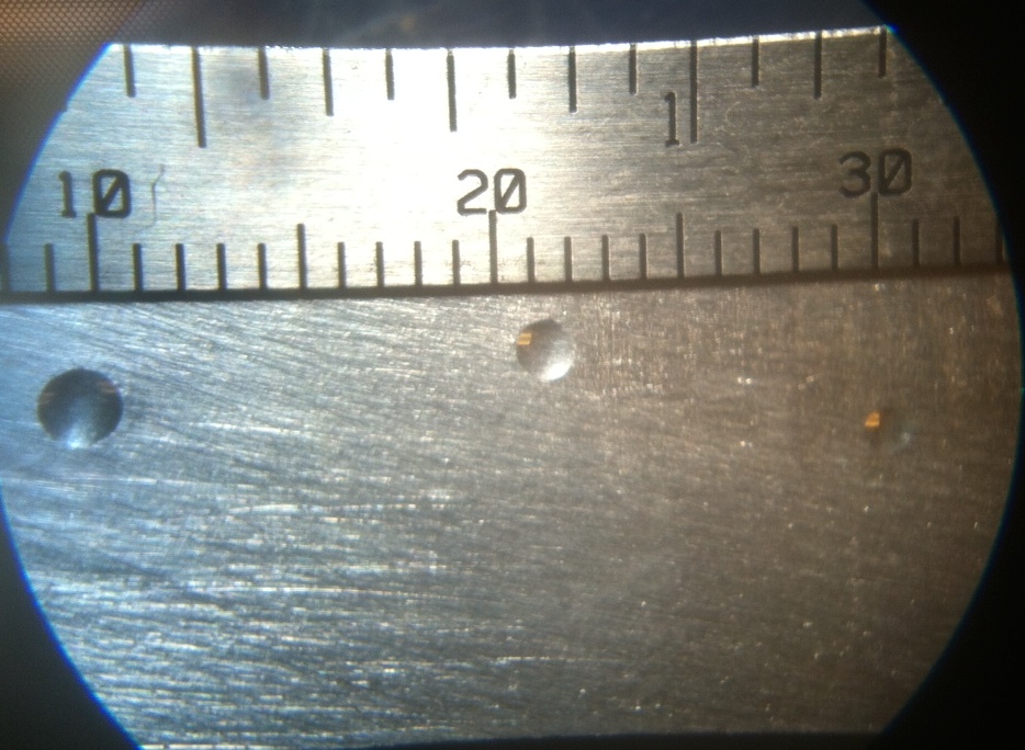
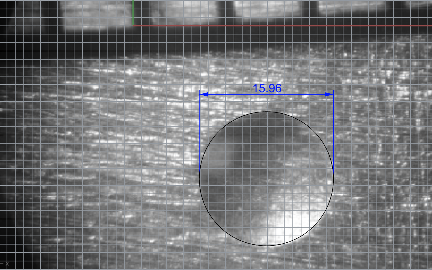
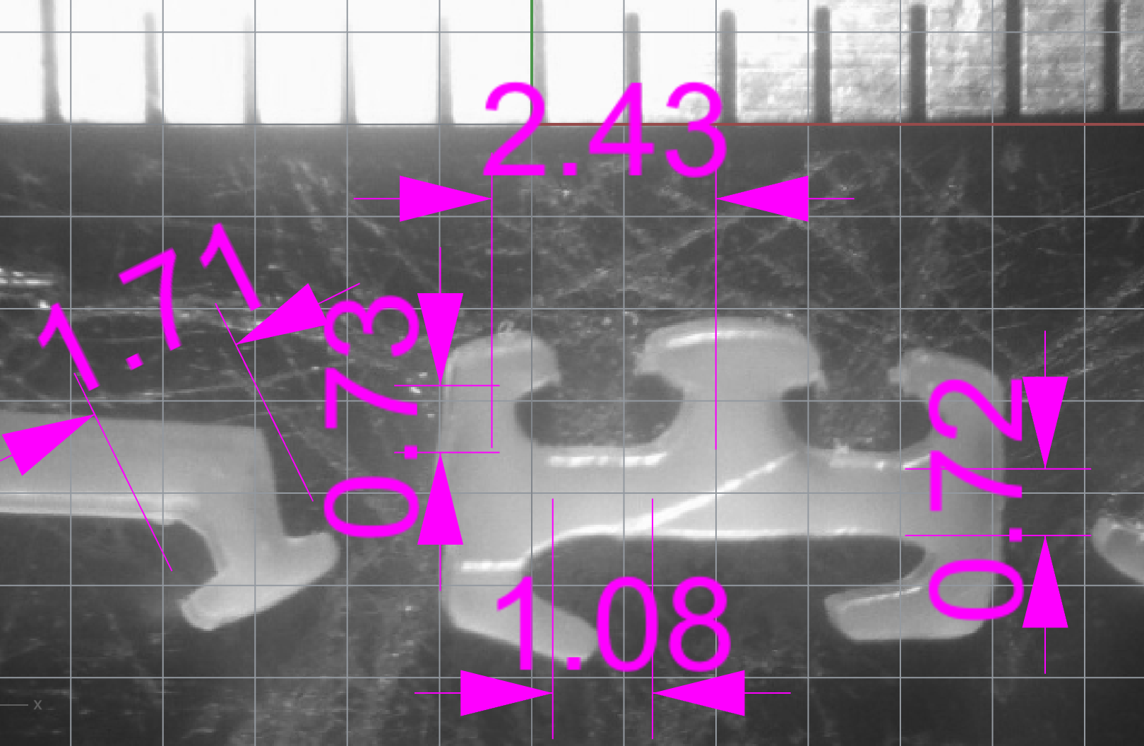
Using a tap guide to hold a .25" hardened ball bearing, I applied 1, 2, and 3 kN loads through the bearing to the surface of the material. The babbit is clearly softer, making much larger indentations for a given load. I photographed the indentations in a microscope, and used Rhino to scale and measure the circular divots. It is important to position both the divot and the ruler ticks in the center of the photograph to avoid lens distortion. The photos below are just to show the three divots -- For the measurement, I used photos of each one individually.
These measurements place the Brinell hardness of Babbit around 27, and that of Aluminum at around 102. These numbers match published figures for babbit and aluminum 6061. Brinell hardness can also be roughly converted to tensile strength -- This gives a reasonably non-destructive way to estimate material strength. Babbit is too soft for most conversion charts, but my measured hardness of Aluminum gives a good estimate of its strength.
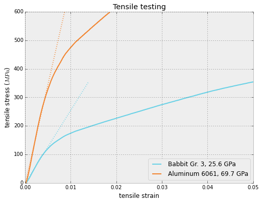
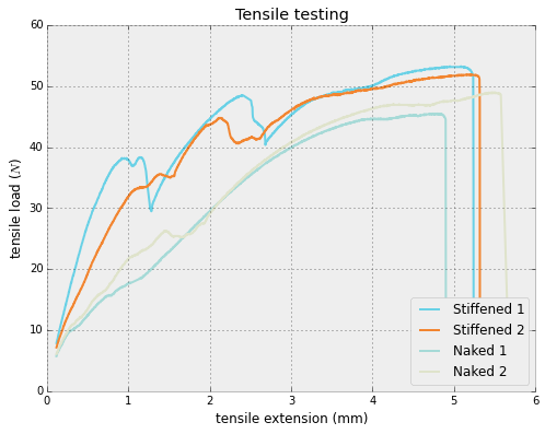
I also tested stiffness of the samples. Aluminum tests roughly three times stiffer than babbit. While the relative stiffnesses are significant, getting these numbers to match published figures was a bit fiddly, due to poor jaw engagement.
Ziploc engagement testing
Over IAP, I built a small thermoplastic extrusion machine and have been using it to make custom "zip-loc" type seals. Being able to make these extrusions myself allows me to specify the load capacity by designing the extrusion die. Below is an animated gif of pulling apart a 10mm section of one such seal, roughly 3mm wide.
There's a lot going when we pull apart the seal, but we care about the first part of separation, before the internal barbs come undone. In this regime, we might be able to model some of the deformation as a simple beam.

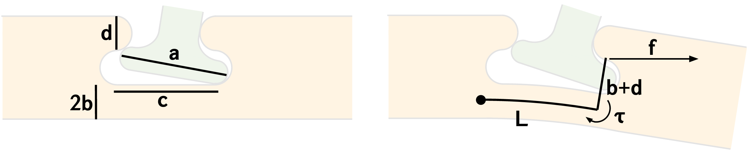
Consider a beam with constant flexural rigidity $EI$, with displacement from rest given by a function $v$ defined along the length. Strain energy stored in a beam is given by $$U = \int_0^L \frac{M^2 dx}{2 E I}$$ where $M$ is the moment along the beam. If one end of a beam is fixed, the other end free, and the only load is a fixed moment $\tau$ at the free end, then the moment along the beam is constant because $EIv''=\tau$. Then $U=\frac{\tau^2 L}{2 E I}$. The work done in loading the beam is $\frac{1}{2}\tau\theta$, where $\theta$ is the equilibrium angle of the free end of the beam with respect to the rest axis. These quantities must be equal, so $$\theta = \frac{\tau L}{E I}$$ Now, in the diagram above, we see $\tau = (b+d)f$.
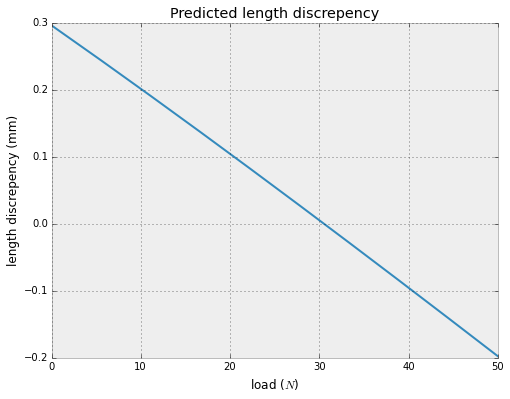
We can draw triangles and take a small angle approximation to predict that the barb will release when $$ d^2 + \left(c+\theta b+\frac{\theta d}{2}\right)^2 > a^2$$ This condition, together with our expression for $\theta$ allows us to predict when the barbs will slip, in terms of the force applied by the instron. Because we have only modeled one deformable member in a structure where everything is deformable, it is reasonable to expect this to be a lower bound on the slipping load.

I found Mechanics of Materials by James M. Gere helpful for these derivations. I used an Ipython notebook for my notes, calculation, and graphing.
Machine Development
This week I thought a bit about spindles for my tube cutting machine. I had been imagining using an abrasive wheel from a dremel tool as my end effector, but I decided that if I'm going to put in the work to build a whole machine, I want to be able to cut shapes into the tube ends. Therefore, I think I will use a standard end mill, instead of the cutting wheel.
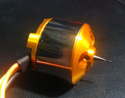
Some folks on the internet have done some cool stuff matching shaft sizes of pin chucks to those of brushless motors to build spindles without the need for additional bearings and belts. I liked this thought, but wanted to take it even further. The BLDC motors are so cheap and interchangeable, we can simplify things even more (and avoid potential causes of runout) by using the end mill shank as the motor shaft. Switching the shaft out of the motor requires an arbor press, but with this tool it was an easy job. For different end mills, just swap the motor!