This week, we were to use motors to move mechanisms we make.
Antimony machine building library
I've long been a fan of Matt Keeter's Kokopelli, but I've been hesitant to start using his newer project Antimony because I like the stability of Kokopelli, as well as the array of output options / CAM dialog, and I don't find the visual data flow graphs to be particularly useful in my design process. This week, however, I decided to check out Antimony, because whatever Matt does is bound to be great, and I could mimic the scripting-only interface of kokopelli by staying in a single node.
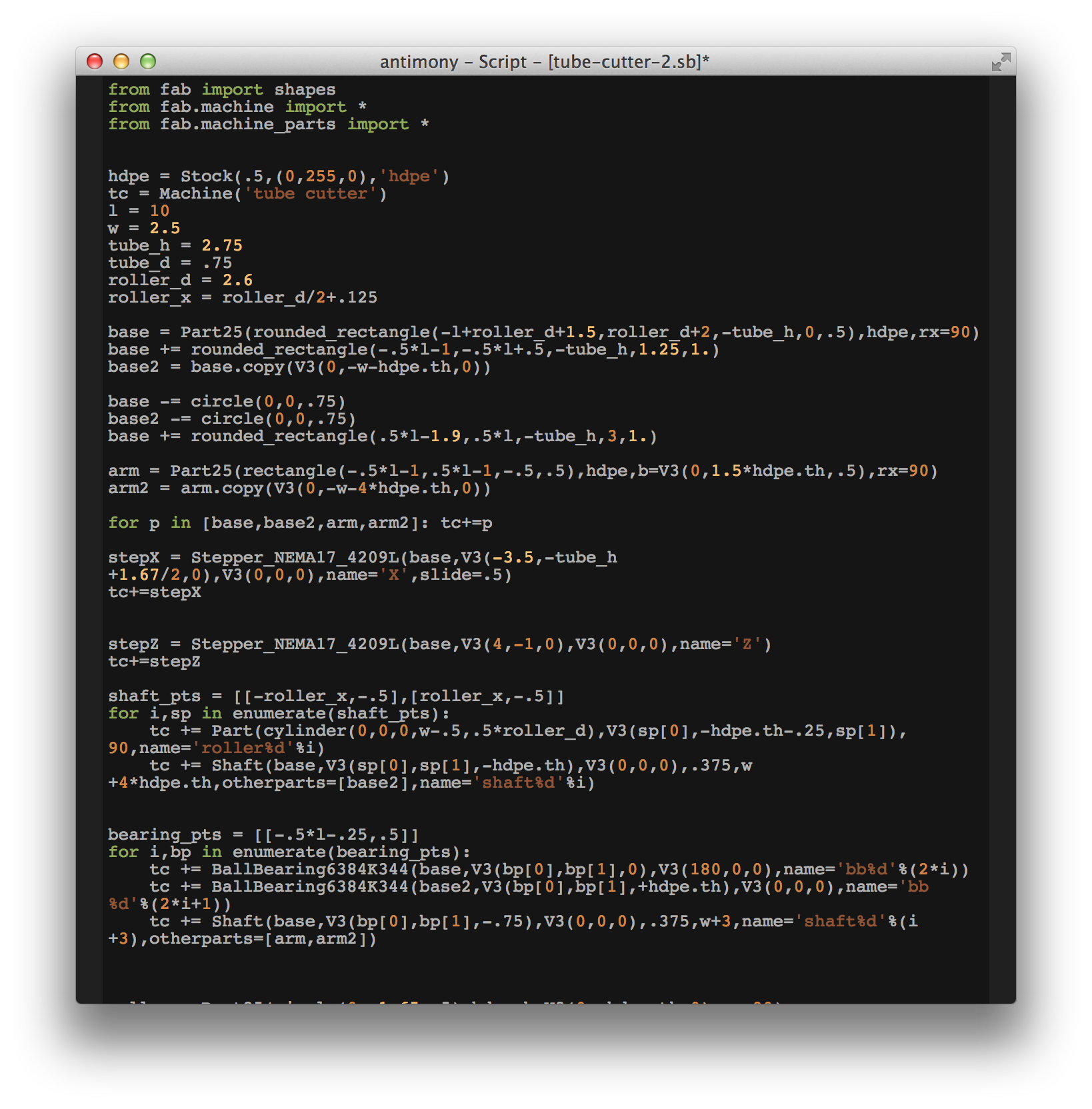
One thing I really like about both Kokopelli and Antimony is the ability to add my own libraries that I can import to Python (e.g. for designing PCBs) that avoid having to recreate a lot of the same work for each design. With this in mind, I wrote the beginnings of a machine building library for Antimony, using the power of object-oriented programming to simplify the design process for machines.
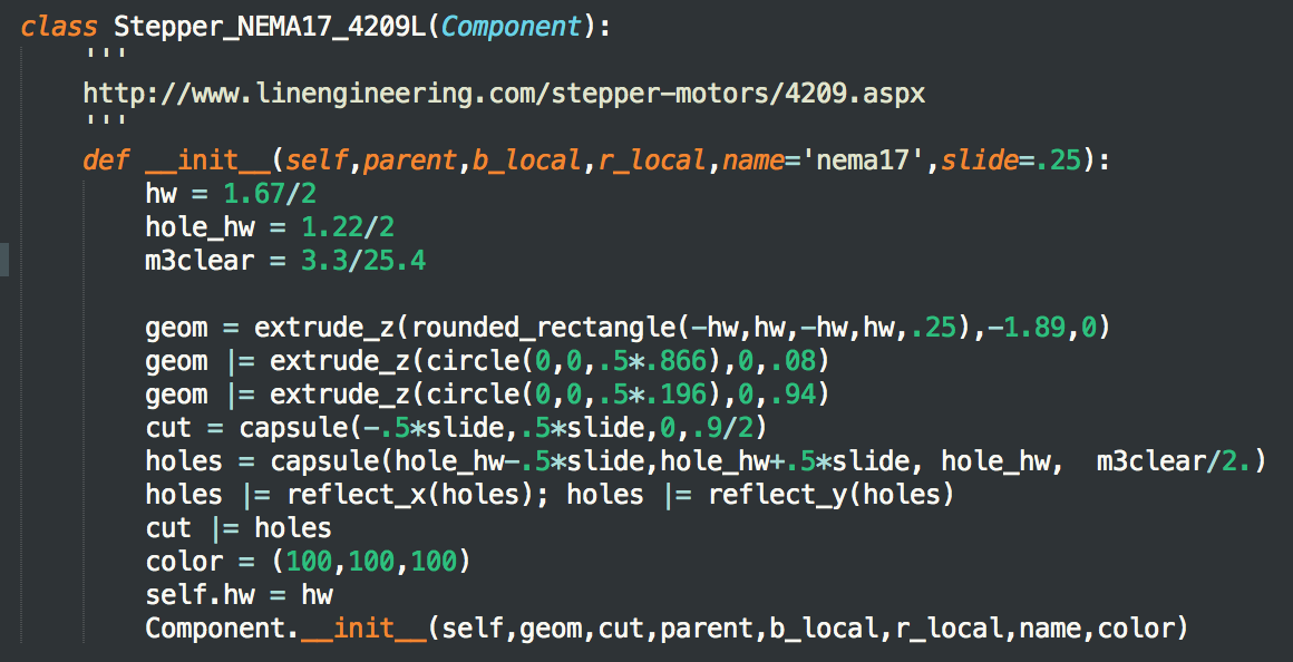
This library has a Machine class, which holds lists of Part objects, and can provide assembled and layout views of the parts. A Part is generally an abstract class, which derives into Part25 (a 2.5D part), Component (an off-the-shelf part with fixed geometry), and (in the future) other common part geometries (e.g. TurnedPart, etc.). The library also has a Stock class (e.g. 1/4" Aluminum) that ascribes color to parts, and can be used to automatically generate cut file layouts. Finally, I also included a Join class for applying joinery between parts (e.g., Captive nut, MTM snap, finger join, etc.).
What's nice about expressing a machine in this way, is how easy it is to establish relationships between parts. Each part carries a local coordinate system, so we can place new parts with reference either to the global coordinate system, or in terms of the coordinate system of another part. This makes placing a bearing Component into a plate very easy. The bearing brings a shape for a cut with it, and that cut is automatically subtracted from the parent Part.
As a test case, I designed a roll feed mechanism for the tube cutting mill I want to build (more on that below). I had a good time writing classes for the McMaster components I wanted to use and attaching joinery shapes to them, all in the DRY (Don't Repeat Yourself) cause.
In the end, the stack-up of geometry proved challenging to render in Antimony on my laptop. It was exceedingly easy to perform CSG between components, but I think interaction at faster rates would be really useful for trying out many design options.
After writing the classes for part types and components, and designing a small machine this way, my hunch was confirmed that by-and-large, the boolean operations necessary for machine design can be phrased in terms of two-dimensional CSG problems, a much more tractable class than the three-dimensional case. There's even a JS library I may play around with.
I think it could be a really powerful capability to build a 3D viewer, where machine components are assembled in this object-oriented way, the CSG is done in terms of polygon boolean operations on top and bottom surfaces of parts. Anybody want to help?
Roller stage for tube cutter mill
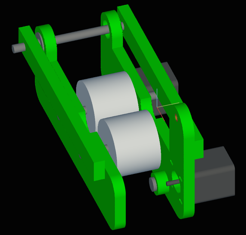
To satisfy this week's assignment, I prototyped a roller stage using the machine design library above. I ended up fabricating a simpler version of the machine I had designed, just for time's sake.
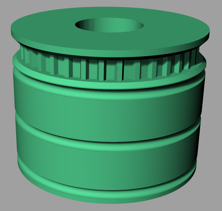
The rollers are just a 3D printed cylinder, with a timing belt profile, o-rings stretched over the outside and bearings pushed into the sides. I used a NEMA-17 unipolar stepper (driven as a bipolar stepper), with a XL timing belt. I used sealed bearings and anodized aluminum shafts, because eventually this will be a hostile environment (water coolant and fiber chips). I played around with ideas to separate the milling area from the timing belt interfaces, but in the end just built this simpler design. There is a simple HDPE scaffold, and I used shoulder screws to secure the idlers. At first I had some trouble with belt alignment, so I turned a better idler on the lathe.
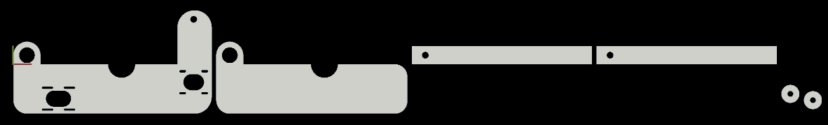
Routing the timing belt was a fun problem -- getting this right has always been a challenge for me. To get it right, I milled a view extra holes to give myself options for mounting the idle rollers.

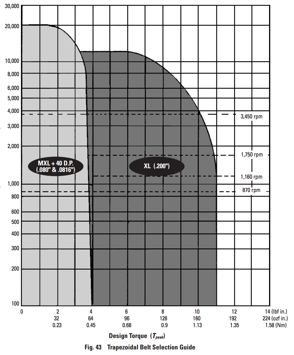
Based on some papers, I decided to be in the 1 N-m torque range over a range of tube diameters. Based on the chart below, this meant the MXL series timing belts might not be good enough.
I just wrote a simple bit of micro-code that listens to the serial port and adjusts the speed based on reciept of "a" and "z" characters.
Capabilities and Applications
My capabilities and applications are growing in breadth, rather than depth.
Lost Foam aluminum casting: I bought all the supplies to do this, but I haven't made my pattern yet. My challenge is finding a part that I need that is easier to make this way than just milling it from a block of aluminum. I was thinking of making a mold for glass blowing -- It would be easy to do with Nadya's hot wire cutter.

JS machine building library: See discussion above.
BLDC tool changer: Cheap and cheerful tool changes by pressing end mills into brushless motors and swapping with a kinematic mount. I bought some bigger brushless motors that I want to try with larger diameter tools. The trouble is most BLDC motors have metric shafts and most tools I use are imperial sizes.
Rotary mill: For cutting shapes in the ends of composite tubes. I'd like to tie together all the one week projects I've been doing towards this goal.
Turn and Burn EDM: The OCR is behaviing nicely now, I need to do work on the toolpathing for it.
Optical flow positioning with reflectance correction: I plan to use this on my rotary mill to do long-range positioning of stock. The optical flow sensor will track a tape measure with a stop on the end. The tape will include light and dark stipes to do drift correction using reflectivity.
3D sewing/assembler: This week, I found the best article I've ever read about how sewing machines actually work, none of the sugar-coated animations you usually see. I had a dream about building a simple lock-stitch stage, feeding in rolls of pre-laser-cut material (probably polymers), and using a vision system to place stitches through holes in the feed stock. This is kind of like the tape-world I described a few weeks ago meets CBA's research.