<br>
[MAS.865](../../) > [Motion](../) > Brushless Motors
## Brushless Motors
#### High Power Density with Control Overhead
---
### The Mechanism
#### Electric Motors actuate with a rotating a magnetic field.
In relation to Ashby's fundamental actuator types, brushless or brushed electric motors are effectively continuously-rotating solenoids.
We have something with magnets, and something else with electromagnets, we use the electromagnets to rotate the field, we pull the magnets along. Rotating the field is called *Commutating* the motor, and can be done mechanically or electrically. With mechanical commutation, we have Brushed DC Motors, with electrical, Brushless DC Motors.
#### Brushed Motors rotate the magnetic field using 'brushes'
Brushes are mechanical switches that use the motor's own rotation to change the magnetic field. Super neat. [Here's a link to Sparkfun's explanation.](https://learn.sparkfun.com/tutorials/motors-and-selecting-the-right-one/dc-brush-motors---the-classic)
And a GIF. While the rotor rotates, different switches are connected to current, and the coils - to - pads relationship is set up such that the current will cause the motor to rotate. Pardon my abbreviated explanation.
Brushes make motors very simple. You just pump voltage (so current) through the rotor, and things happen. However, there are resistive losses at the brushes, as well as friction losses.
#### Brushless Motors rotate the magnetic field with switches.
Power transistor technology means that we can do this electronically - use a computer (or simple timer) to switch the phases.
So we can make the coils stationary, and 'artificially' switch the direction and timing of current flowing through them.
Here's an example of '6-step' commutation. This is incredibly common for speed control, and simpler devices, as it requires very little processor work. It can also be done in an open-loop fashion, where we blindly switch currents at a set rate to control for speed.
Here's a nice GIF of sinusoidal commutation (where phase currents follow a nice, smooth wave). This is more ideal than 6-step commutation for a number of reasons, some of which are discussed in the next section.
We can see the three current vectors (that translate into a combined magnetic field vector). The permanent magnetic field of the rotor follows this electromagnetic field around.
### Control
Control of Brushed DC motors is straightforward, we use one Full H-Bridge to drive current in both directions across the coils.
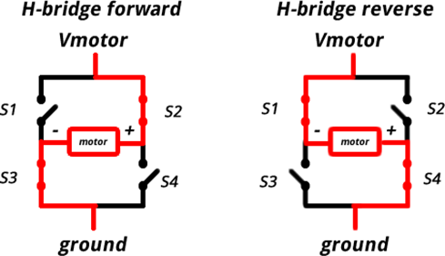
However, with a brushless motor requires a bit more. We use three Half H-Bridges to source and sink current between the three coils, each having a common connnection to one another.
#### Commutation Schemes
While it's possible to blindly drive the switches at a set frequency (determining rotor speed) it's really advantageous to drive the coils with some form of feedback on the rotor's relative electric position. There are a few ways to do so.
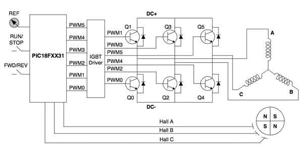
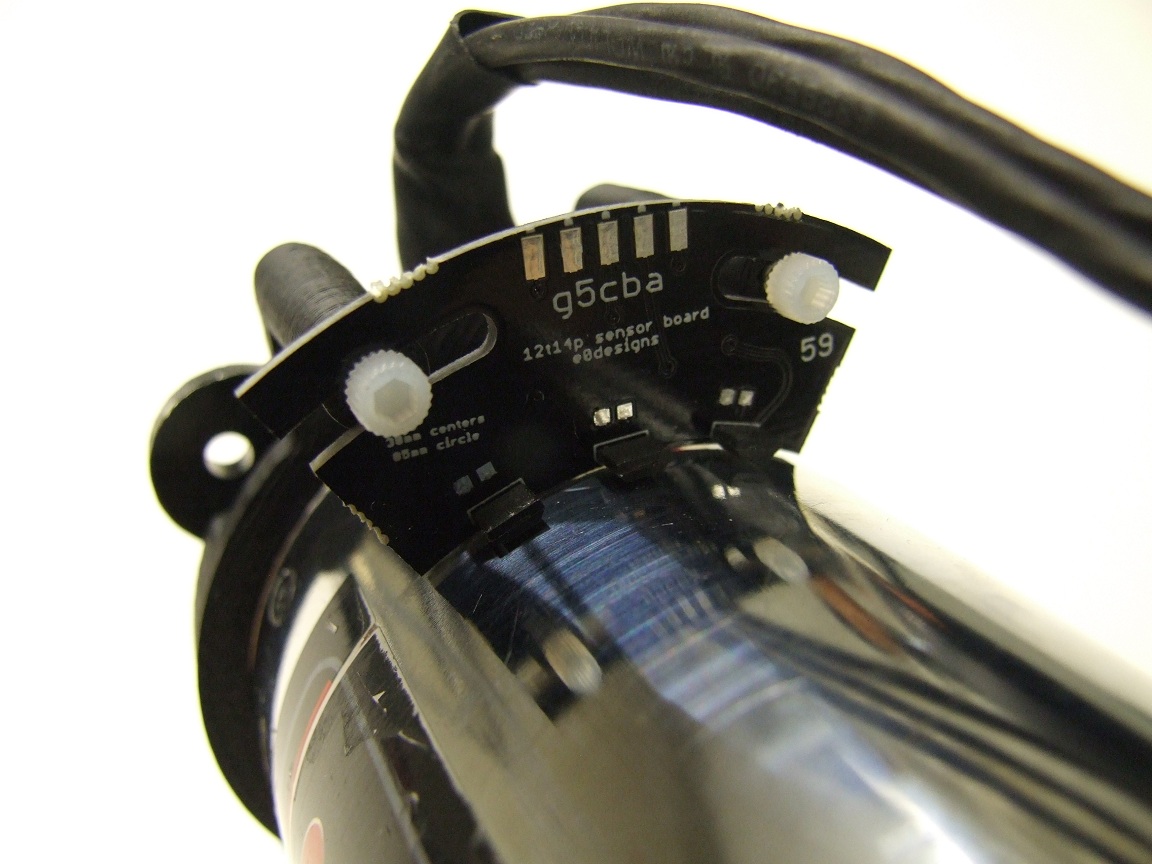
**Hall Effect Sensors & Six Step**
Hall effect sensors measure the position of the rotor's magnets:
This is a straightforward and very popular method for commutation, and is always useful information, but only completely effective for motor control schemes using 6-step commutation.
**Back EMF & Six Step**
Hall sensors add complexity, so Back EMF has become popular, although it doesn't work at lower velocities.
With Back EMF, we take advantage of the fact that at any given time one of the coils is not being driven. This means that we can measure it's voltage (it's acting like a generator) and use the zero-crossing point (when that voltage is 1/2 of the voltage driving the other two phases) to inform our commutation (which should happen shortly thereafter.
Because we're driving the other two ends of the coil whose voltage we're measuring with a PWM signal, there's some complexity here. I won't get into it, now, but for jumping off try [this](https://www.digikey.com/en/articles/techzone/2013/jun/controlling-sensorless-bldc-motors-via-back-emf) or [this](http://www.ti.com/lit/an/sprabq7a/sprabq7a.pdf).
**Field Oriented Control**
aka FOC
This is 'modern' motor control, and represents the state of the art. FOC uses a good deal of embedded computing, and has a control schematic that looks like this:
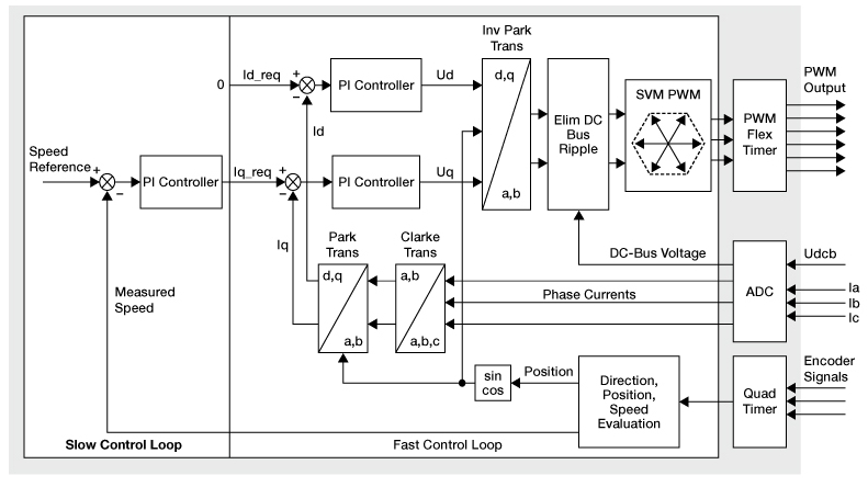
We use rotor position to drive a sinusoid of phase currents, and do control over those currents to overcome inductive lag.
Normally, position information comes from an encoder, but Sensorless FOC exists where a state estimator is used to guess at the rotor position.
In order to jump off here, try [this](http://www.copleycontrols.com/Motion/pdf/Field-Oriented-Control.pdf), a brief overview, and [this](http://www.ti.com/lit/an/sprabq3/sprabq3.pdf), a monster, from TI, on sensorless FOC.
#### Circuits
A number of brushless motor controllers are available in the open-source world:
[ODrive](https://odriverobotics.com/shop)
[VESC](http://vedder.se/2015/01/vesc-open-source-esc/)
[Ben Katz](http://build-its-inprogress.blogspot.com/search/label/Motor%20Control)
[MKBLDCDriver](https://gitlab.cba.mit.edu/jakeread/mkbldcdriver)
Here's the schematic that I'm most familiar with:
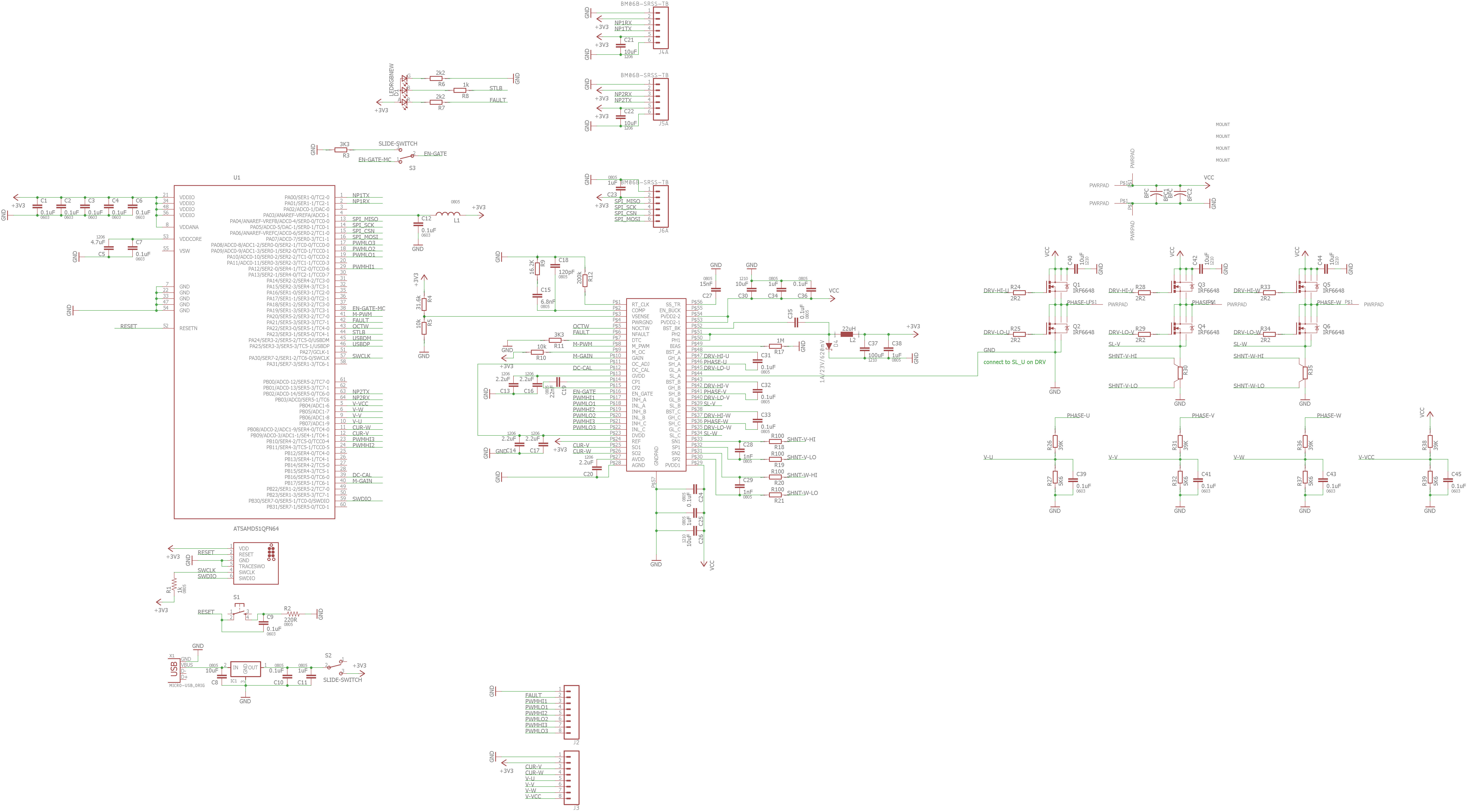
And the board,
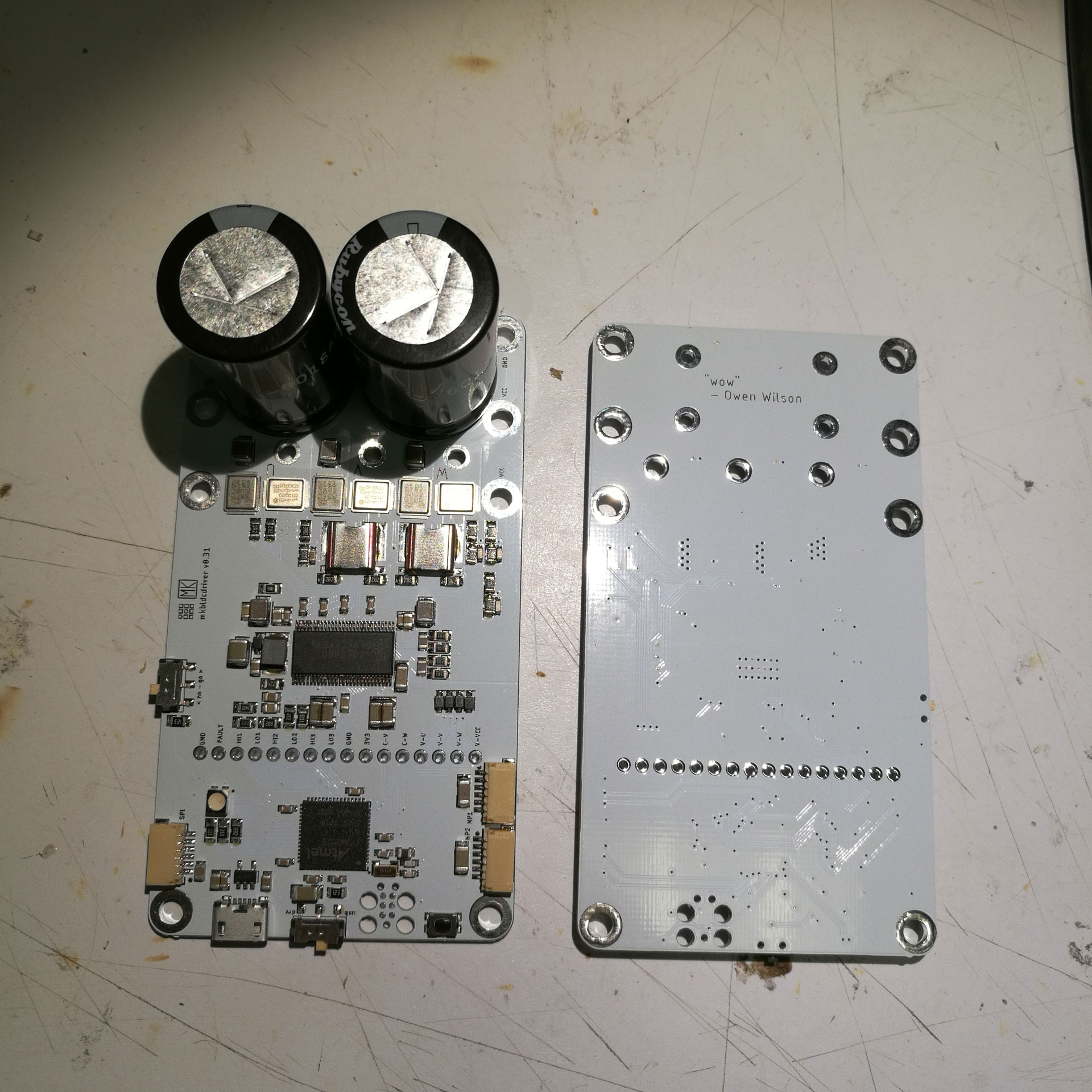
In each of these boards, we find a microcontroller, a gate driver, three half-bridges (6 MOSFETS), and current and voltage sensing circuitry. And a few BFCs never hurt.
#### Typically Available:
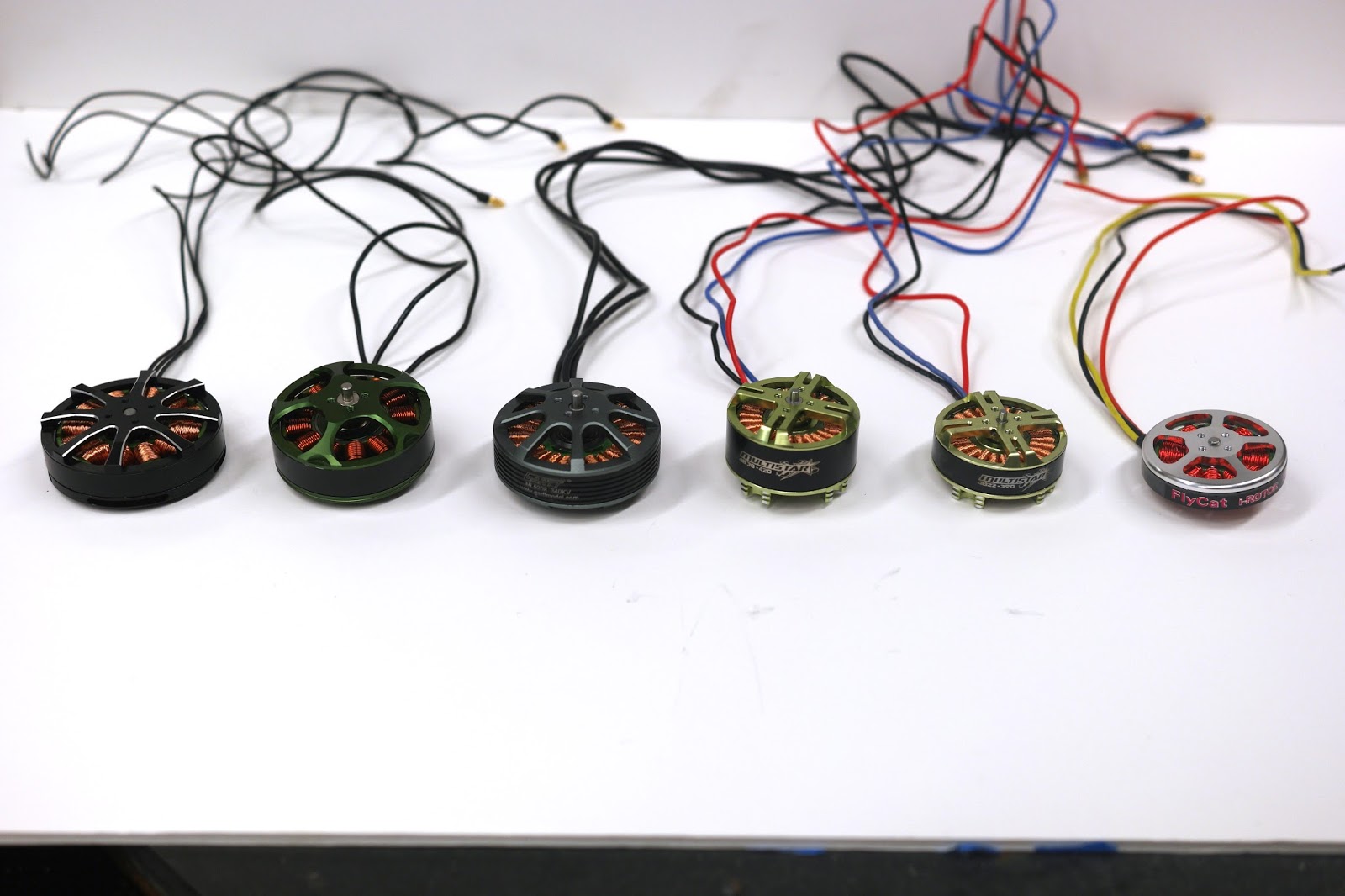
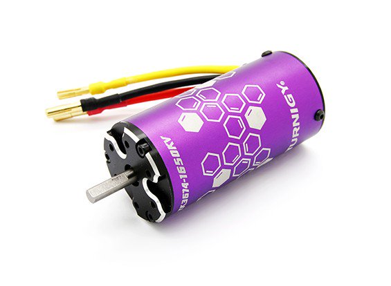
For motors, I am deeply in love with [Hobbyking](https://hobbyking.com/en_us/power-systems-1/electric-motors/size.html).
'Outrunner' Motors (rotor wraps stator) are popularized by drone enthusiasts and have fairly high torque densities due to an increased gap radius.
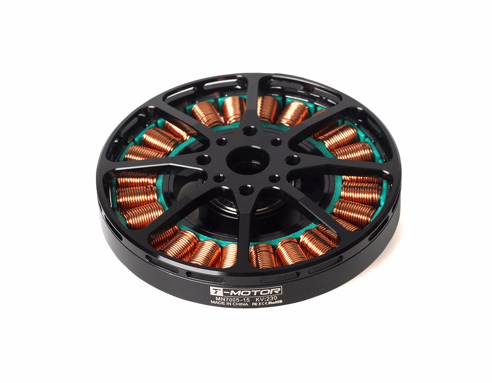
[here](http://store-en.tmotor.com/goods.php?id=475)
Inrunners (rotor inside stator) are great for speed.
To control these, look [here](https://hobbyking.com/en_us/power-systems-1/speed-controllers-esc.html) to start, but preferrably pick up one of the open-source ESC's mentioned above - or try building your own. With off the shelf ESCs, open loop speed control is the only thing you can do.
### The State of the Art
The design of BLDCs is not changing radically - it's a good idea, and it works.
**There is one exception to this** - [Thingap Motors](http://www.thingap.com/) use an ironless winding [(patent here)](https://www.google.com/patents/US20130300241) and have relatively high torque densities. The [performance is impressive](http://www.thingap.com/standard-products/) but they cost ~1k at the low end.
What is interesting is where BLDCs are being used, controlled, and how they are being designed (shape, new densities). Take a look at [The Biomimetics Lab at MIT's](http://biomimetics.mit.edu/research/optimal-actuator-design) discussion on optimizing gap radius, etc.
The MIT Cheetah team had their motors custom made to optimize for torque density (at a cost of total power density). Their discussion is really interesting, you can read [This Paper](../papers/mit-cheetah-actuator.pdf), a great intro to the state of the art in robotic control, of which Brushless Motors and their cousins play a large role.
As well, [Ben Katz'](../papers/katz-thesis.pdf) thesis contains an excellent review, and more intelligent discussion, on FOC, motor selection, etc.
And [Simon Galouche's](../papers/kalouche-thesis.pdf) thesis contains a similar review on actuator selection for robotics.