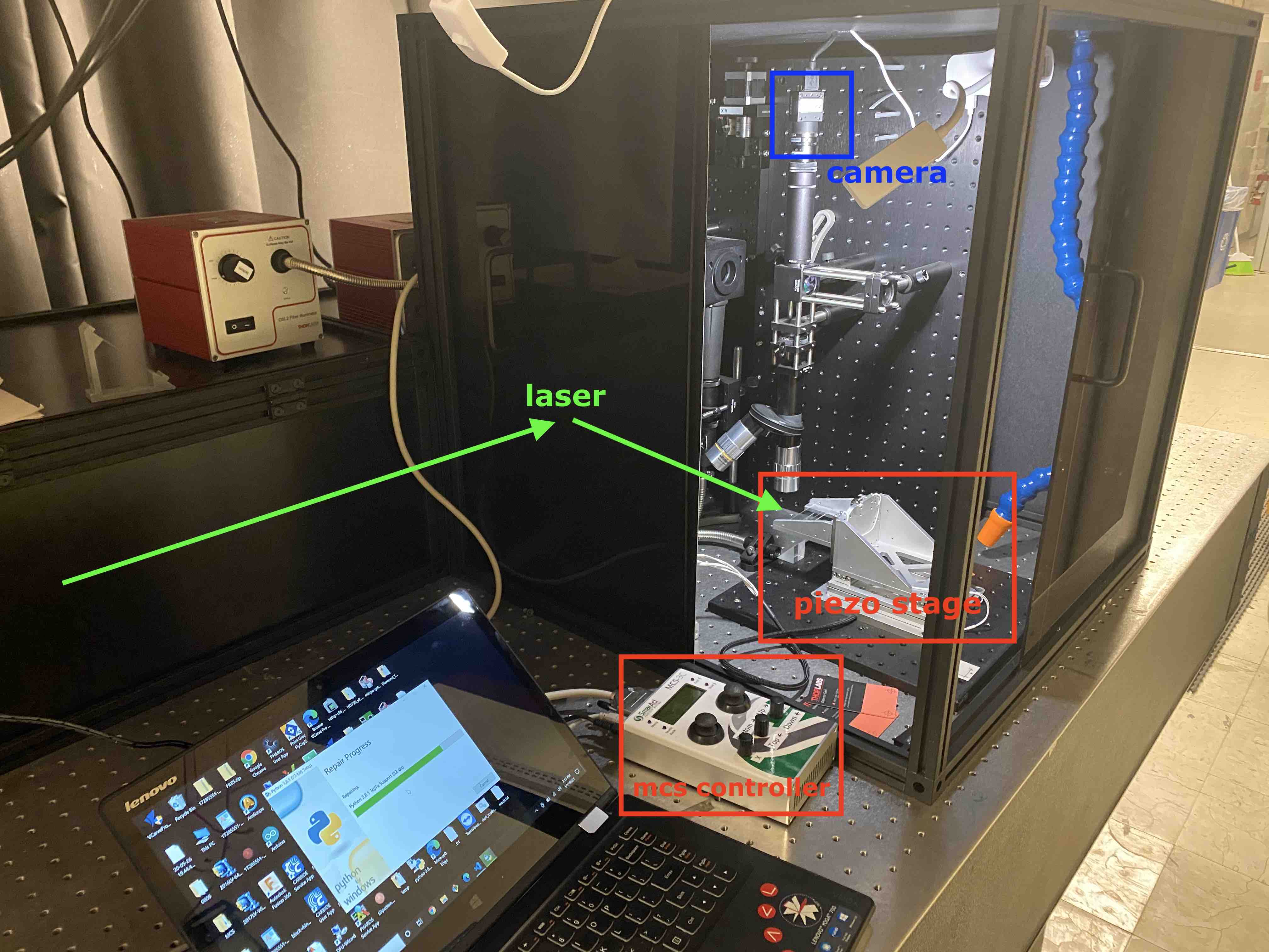
As of the start of class, the ultrafast laser system functions with a
custom python GUI (mimmicked after the Oxford laser machining control
software) that communicates with both the stage and laser.
user quick start
With the laser and stage turned on, run
the `interface_py.py`
script to start running the PyQt application interface.
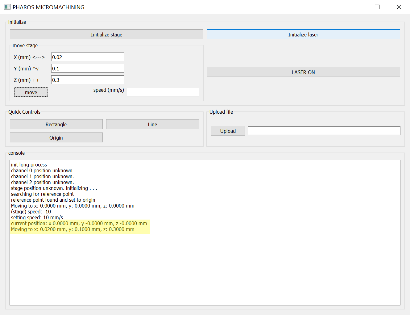
First click "Initialize stage" - when the stage powers on it sets whatever
it's current position is as the origin, initializing the stage with home
the axis and bring the stage to it's true origin.
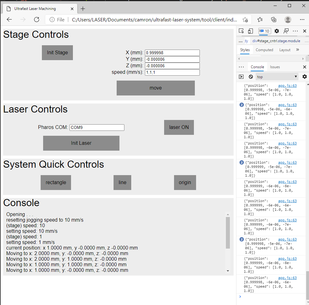
Then you can use the 'move
stage' box to send the stage to some . The console spits
out logging info about where the stage is, how fast it's moving, and
whether the laser is on, etc.
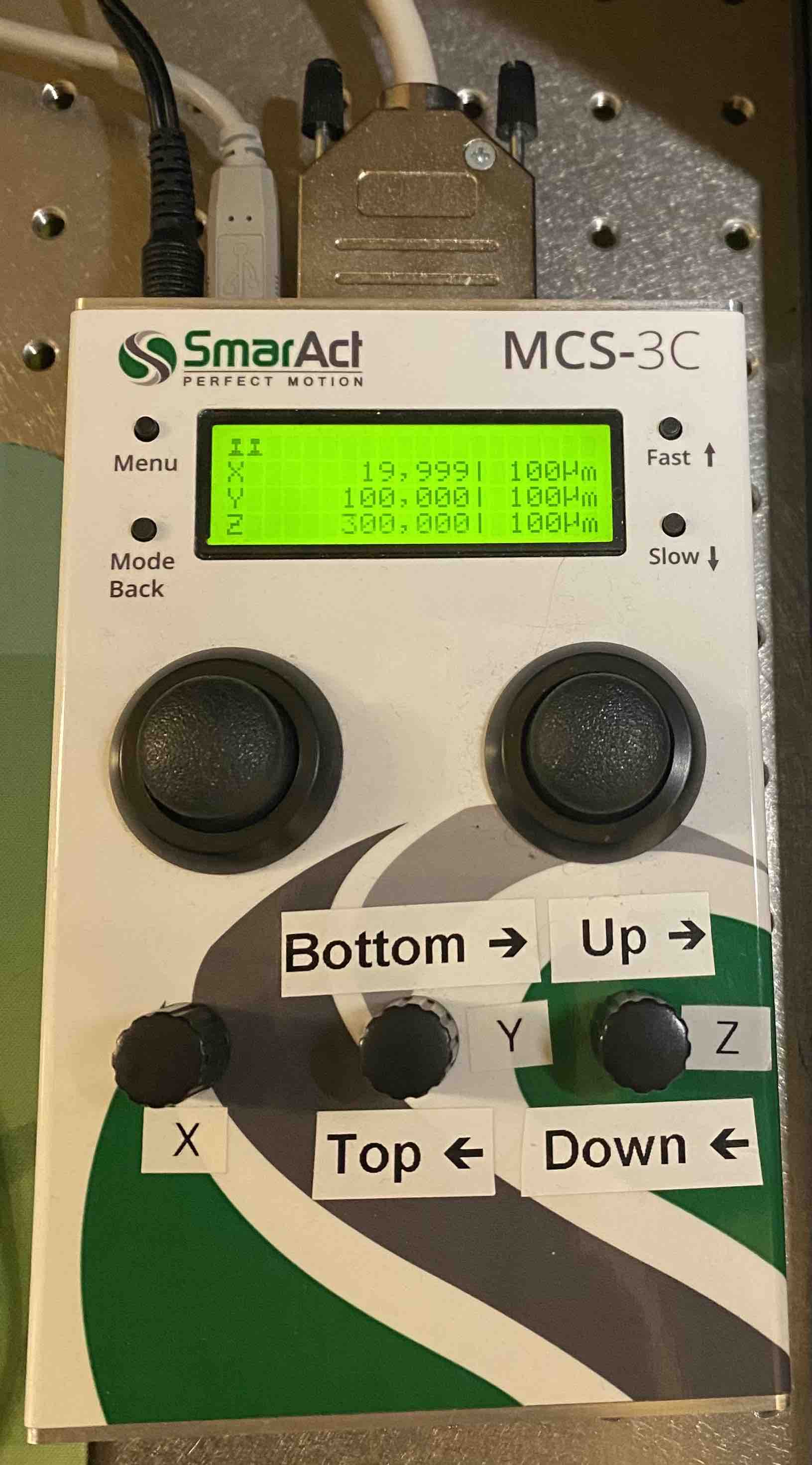
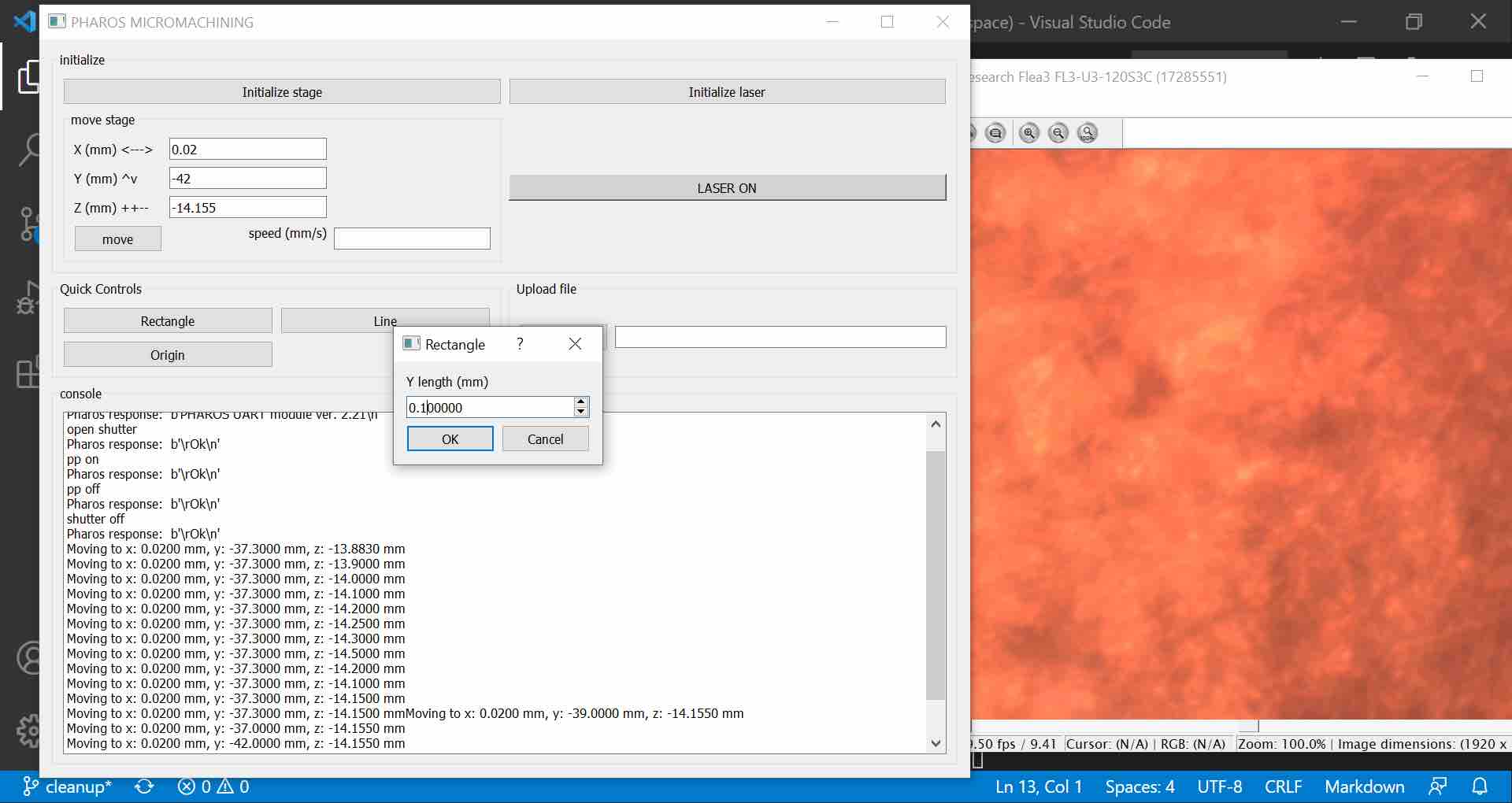
Below you can see I sent the stage to (x=0.02mm,
y=0.1mm, z=0.3mm), verified by the position on the MCS controller.
The GUI has a "quick control" panel which allows you to machine simple
geometric paths based on user input dimensions or move the stage to pre-set
positions (aka just the origin) without needing a separate toolpath input.
To test this, I tried machining a square into Post-it note.
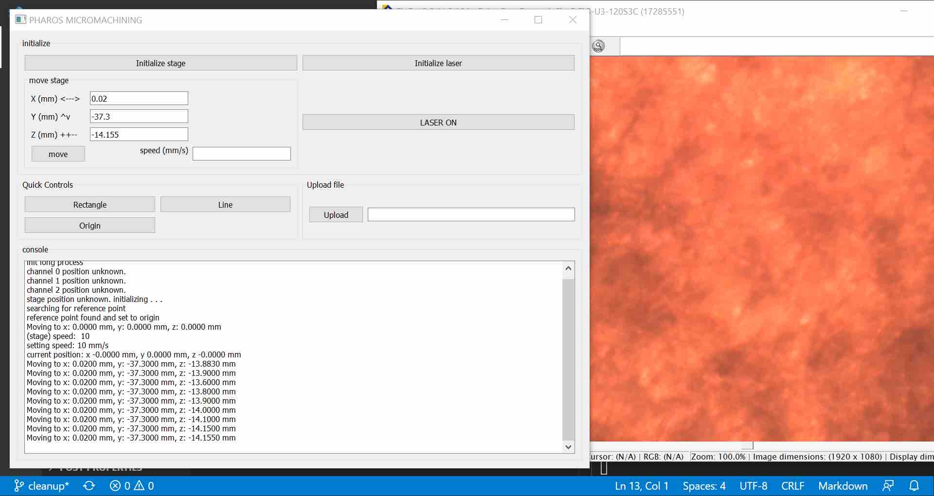
To start, we need to manually position the sample at the focal point of the
laser. This is done using the camera and FlyCapture software to bring the
sample into focus with the current objective lens. This process is a bit
tedious so it's easier to use
MCS joysticks to find the correct position; however, as of now you can't
switch between using the joysticks and the software to control the stage
because it'll break the software's control over acceleration (need to
debug), so I do the following round about steps:
initialize stage so it's position is absolute
find focus using MCS controls
take note fo the position
turn the stage off / on and re-initialize
move to noted position - you may need to adjust by a few microns.
Here is the final stage positions with the focused fly capture real time
image to the right.
Once everything is aligned, click the rectangle button. It will open a
popup which prompts the user for x length, y length, speed, and number of
passes to do when machining the rectangle.
As of now, the micromachining software does not have control of the laser
power percentage - that needs to be manually set in the PHaros Service App.
then it's ready to go and the laser will turn on once you hit start.
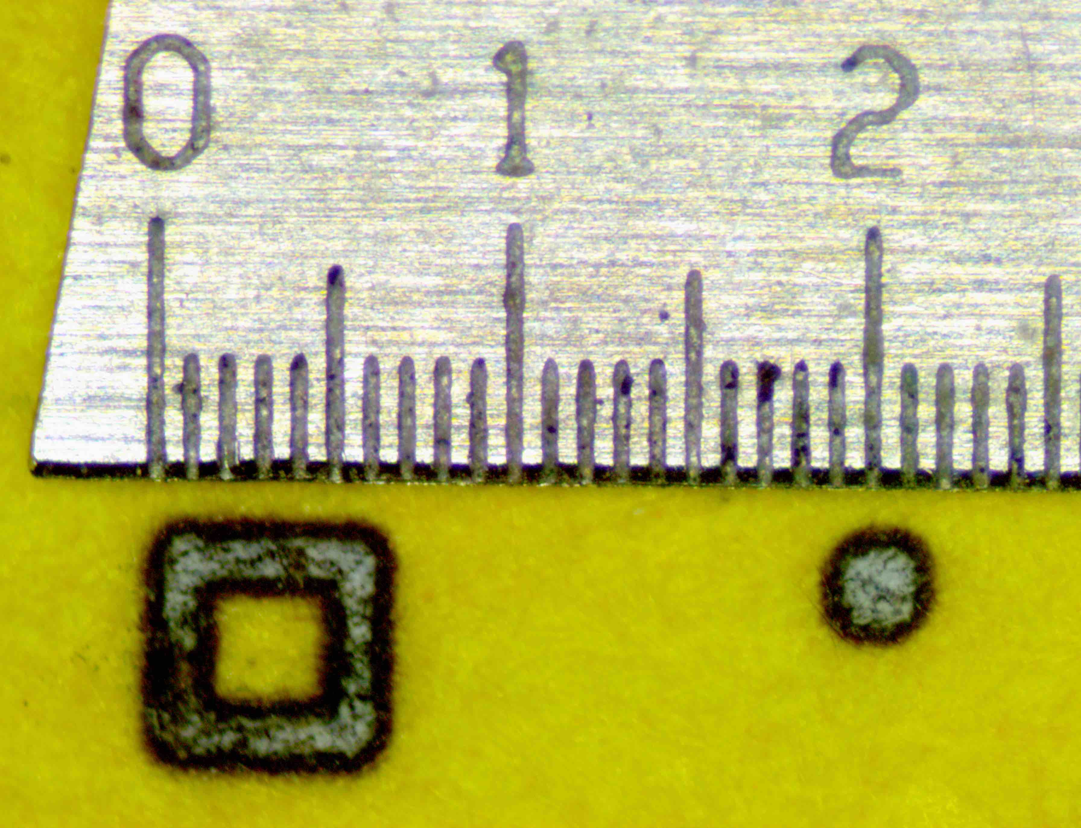
I made a 500um by 500um square and a 100um by 100um square in the post-it note at 100%
laser power, 0.1mm/s speed, and 10 passes.
Note that the machining parameters are not optimized at all so the feature sizes aren't great off
the bat.
Paper is a random test sample because it's what was sitting next to me - but it
ends up being an interesting material to laser machine with the femtosecond
pulses. The ultrafast laser has an extremely small heat-affected zone (HAZ)
because the length of the pulse is shorter than the thermal dissipation of
the photon energy deposition.
I was hitting the flimsy peice of paper with 100% of the Pharos laser power
aka 1.4 GW laser pulses
(0.4mJ max pulse energy over ~290 fs), but it wasn't catching on fire - as
would be the case if I tried the same thing with the Oxford.
Femtosecond lasers are surprisingly safe becuase they're too fast to cause
damage and have been
used to create voxel holograms safe for human interaction
-
Fairy Lights in Femtoseconds.
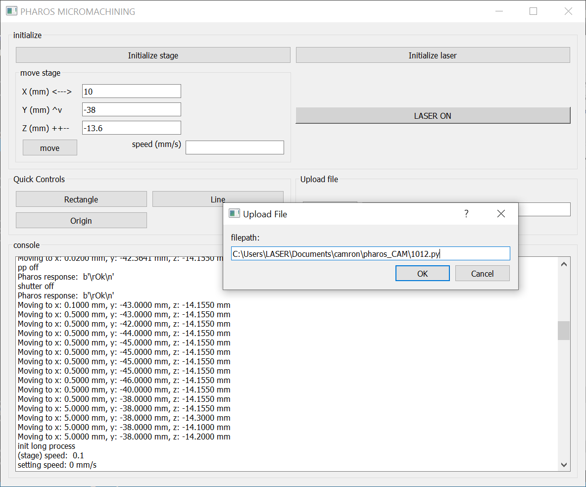
To make more complex toolpaths, I wrote
a Fusion360
post processor which
outputs a python script that can be loaded into the software using the
"file upload" button.
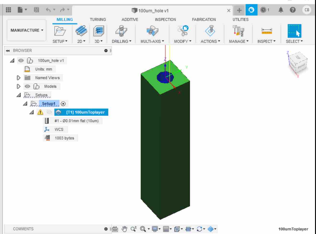
For example, this 100um diameter hole from fusion
makes a circle in the paper. Note that there's not a "quick control" button
for circles because the stage axes are not in sync so curves need to be
segmented into x and y line segments - which is why it's easier to make
Fusion do it.
but this is where things get really hacky because the fusion post processor
is exporting a python script which is directly loaded into the pharos
software which reads commands from
a pseudo
g-code python class . . .
there's definitely a better way to be doing this.
Also, the fusion post processor is it's own hack because it expects 2D
milling manufacturing processes - this allows the laser toolpaths to be
more complicated than just cutting sheet material. however, it would also
be nice to quickly load 2D cutting toolpaths if I stick with Fusion, then
I'd like to expand the postprocessor manufacturing cpaabilities.
UI improvements to do:
control stage without arrow keys or buttons instead of inputing
numerical value each time
figure out how to allow stage control from the UI and MCS Joysticks
in the same power cycle
laser power control over serial to access to it from the toolpathing
multithread console output so that it write as the toolpath goes
instead of waiting until the end
Optics improvements to do:
realign the camera and/or laser so that the laser is in the center
of the camera frame and the motion matches stage movement IRL
verify that the camera and laser have the same focus point - or
determine reproducible offset for correcting toolpaths.
clean optical elements and check for aberrations in the beam path -
it's been a couple years since anything's been adjusted
CAM improvements to do:
. . . hmm . . everything . . .
i think before I can commit to a solution here, I need to
figure out how committed I am to the MCS controller - would it be
possible and beneficial to drive the piezo stages from a lower level ??
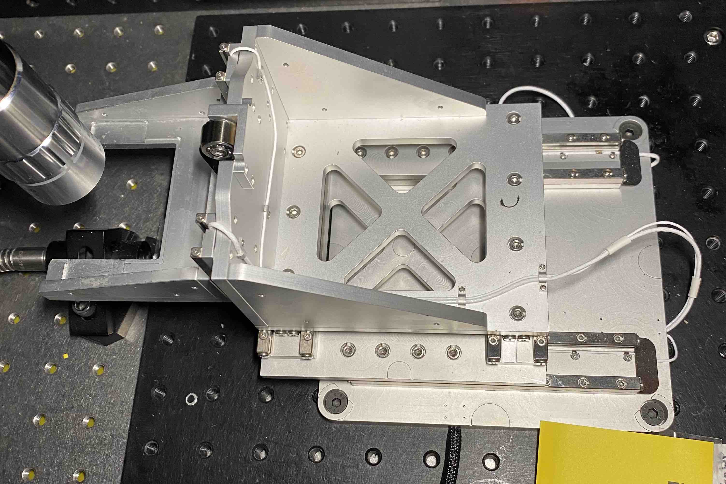
piezo stage controls
The stage we have now is made up of six
SmarAct SLC
Series "Stick-Slip Piezo" linear stages.
The x-axis is made up of
two SLC-24105
linear railings, the y-axis is
two SLC-24120
railings, and the z-axis
is two SLC-1760
railings. From what I can tell, the only difference between these models
is the dimesnions, with the SLC-24 series being a bit more rigid than the
SLC-17 series because of it's thicker width and height.
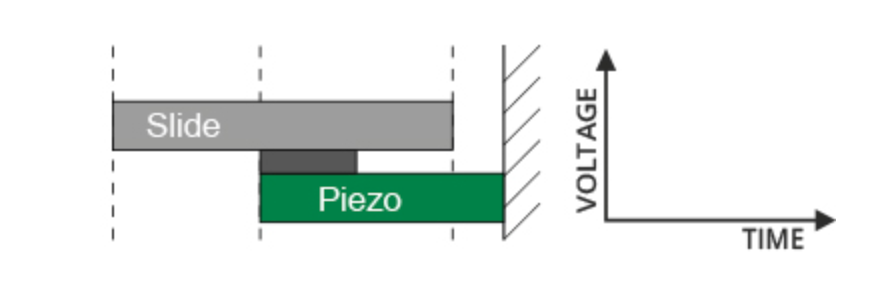
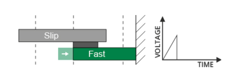
The stages are controled using SmarAct's patented drive technology, they've
named "Stick-Slip". A piezo actuator is attached to the stationary base of
the stage and then couple to the slide of the guideway with a friction
element which is permanently stuck to the piezo actuator.
When a voltage is applied, the piezo actuator lengthens. When the voltage
is applied slowly, the slide will move with the actuator "stick"-ing to the
friction element.
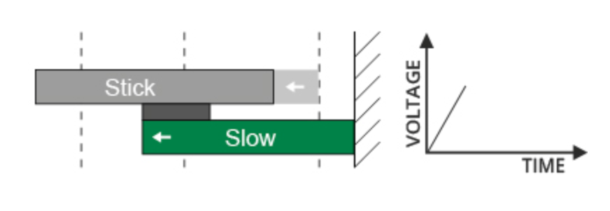
When the voltage is applied quickly, the friction elements moves fast along
the slide, causing it to slip and stick to a new stop. This process can be
repeated to acheive macroscopic travel and is refered to as "step mode"
images from here.
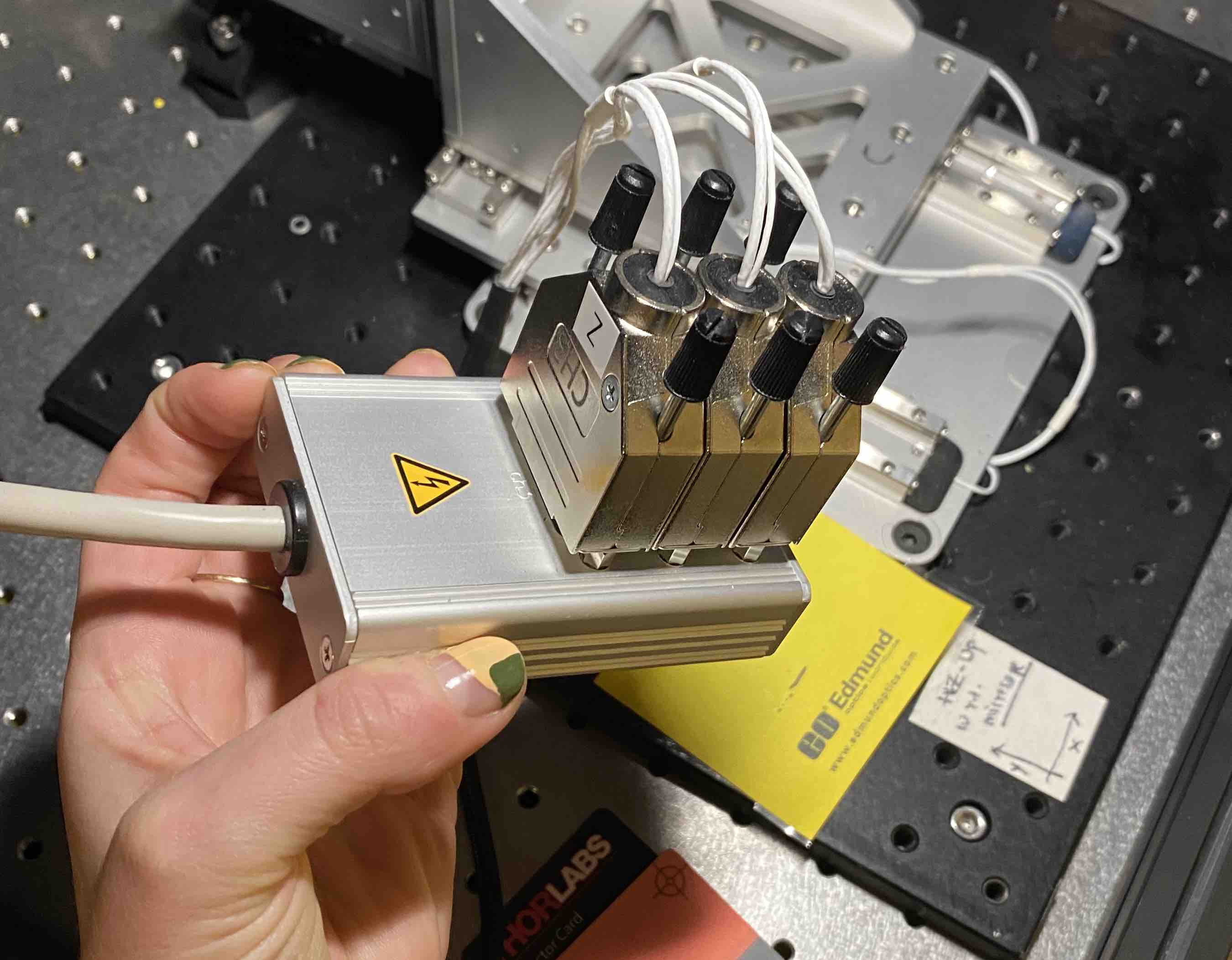
The sliders are then connected to
SmarAct's
MCS (modular control system). They are first attached to the
sensor module that digitizes optical
sensor data for closed-loop position control.
From
the
User Manual , this sensor module (MCS-3S-EP-SDS15-TAB) has nanosensors
for three channels of stick-slip positioners, with a DSUB connector for a
table-top housing.
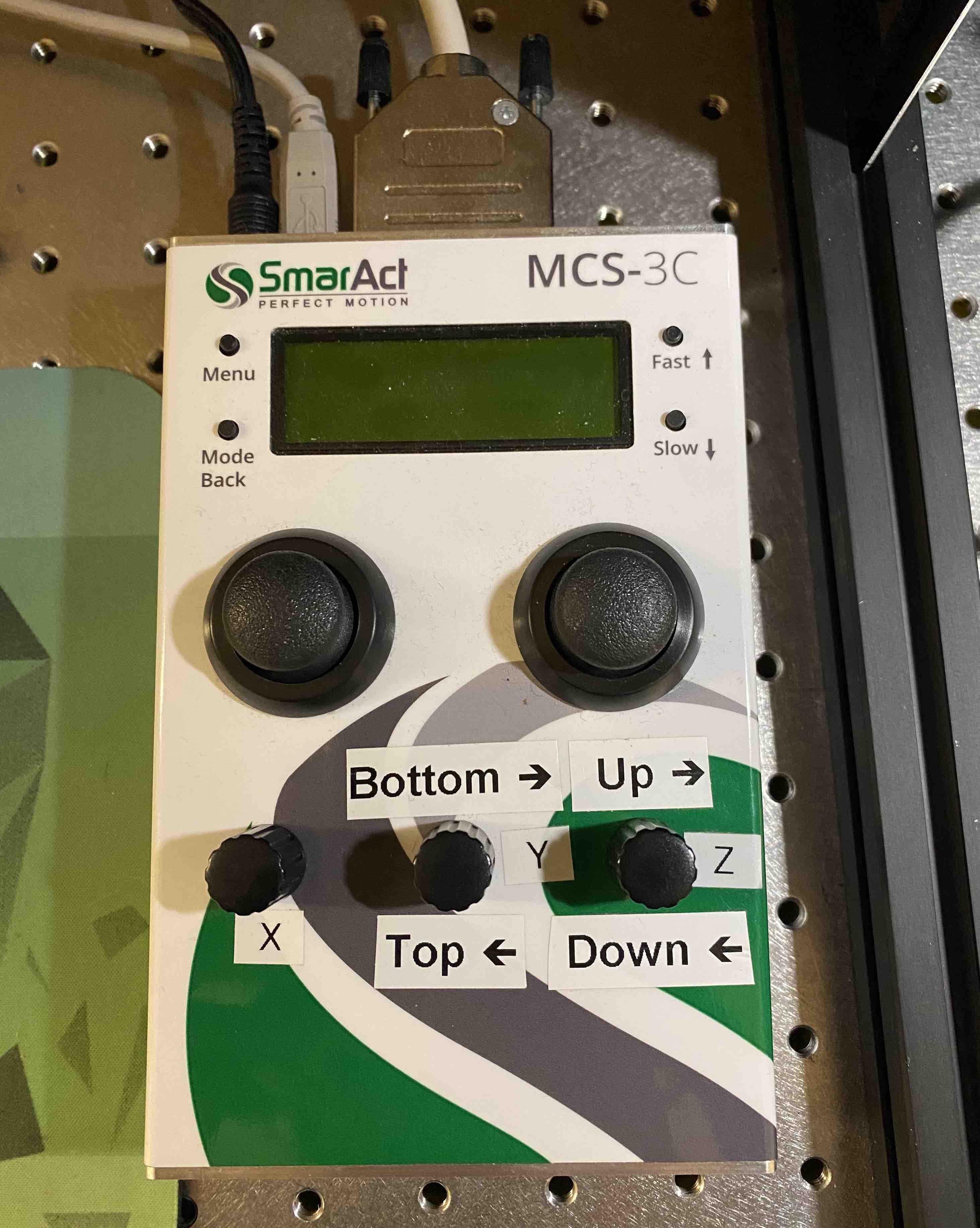
then the sensor module is connected to the main controller module which also
houses the driver module.
This controller module (MCS-3CC-3H-USB-TAB) has drivers for 3 stick-slip
high current channels, a hand control module, USB interface and table top
housing. The integrated sensor is not in the main controller, but I think
that's because there is a separate sensor module.
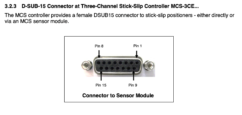
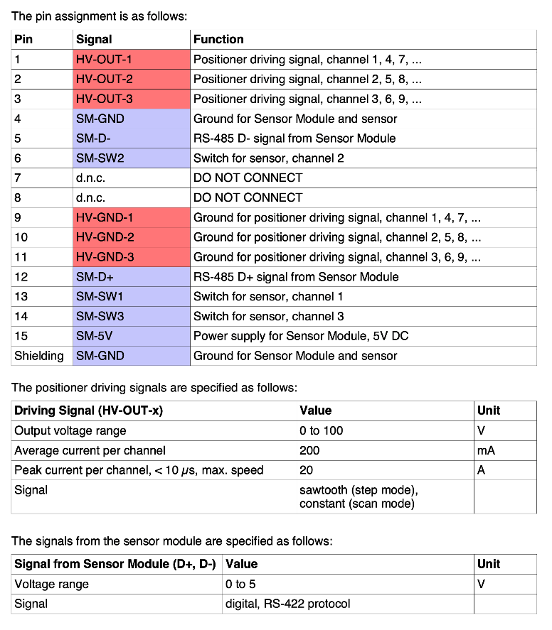
I talked with Jake about bypassing SmarAct's controller and drivers
software since they're bulky and it's not obvious how to coodinate multiple
axes for 3D toolpathing - although, I'm not yet confident open sourced or
custom piezo drivers would be the best use of time. I think this is the
level that I would come in
with different piezo drivers or controls, so parkng this pinout table here
to keep in mind as I revisit current stage control programming.
The MCS software comes with it's own C programming libraries for
controlling the main module in the form of a .dll file (Dynamic Link
Library), a windows-specific shared library for compiling c programs. The
MSCcontrol.dll includes a set of functions for both synchronous and
asynchronous control of the stage system.
Initially, I implemeneted basic stage control (stage and laser
initialization, stage homing, and simple rectangular machining) in c programs
with
the MSC
control header file. For example, here is
the
stage initialization:
#include <stdio.h>
#include <stdlib.h>
#include <stdbool.h>
#include <time.h>
#include <Windows.h>

#include "include\MCSControl.h"
#include "include\stage_utils.h"

void delay(int sec) {
  int ms = sec * 1000;
  clock_t start = clock();
  while (clock() < start + ms) {
    ;
  }
}

void findReference(SA_INDEX handle) {
  for (int i = 0; i < 3; i++) {
    checkErr( SA_FindReferenceMark_S(handle, i, SA_BACKWARD_DIRECTION, 0, 1));
  }
}

int main() {
  SA_STATUS error = SA_OK;
  SA_INDEX mcsHandle = openSystem();

  // check all three channels are awake
  unsigned int numChannels;
  checkErr( SA_GetNumberOfChannels(mcsHandle, &numChannels) );
  if(numChannels != 3){
    printf("%d channels found. Should be 3 . . . exiting!\n", numChannels);
    closeSystem(mcsHandle);
    return 1;
  }

  // check if position is known
  // ch 2 = Z
  // ch 1 = Y (perpendicular to source of laser)
  // ch 0 = X (parallel to source of laser)
  boolean needInit = checkReference(mcsHandle);

  if(needInit == false) {
    printf("Stage already initialized! \n");
    closeSystem(mcsHandle);
    return 0;
  } else {
    printf("Stage position unknown. Initializing . . . \n");
  }

  // set the channel reference speed value to automatically optimize
  for (int i = 0; i < 3; i++) {
    checkErr(
      SA_SetChannelProperty_S(
        mcsHandle,
        i,
        SA_EPK(
          SA_SENSOR,
          SA_REFERENCE_SIGNAL,
          SA_REFERENCE_SPEED),
        -1
      )
    );
  }

  // find reference points
  findReference(mcsHandle);

  delay(10);


  needInit = checkReference(mcsHandle);
  if(needInit == true){
    printf("waiting 10 more seconds . . . \n");
    delay(10);
    needInit = checkReference(mcsHandle);
    if (needInit == true){
      printf("searching for reference point again . . . \n");
      findReference(mcsHandle);
      delay(10);
      needInit = checkReference(mcsHandle);
      if (needInit == true){
        printf("Initialization failed. Exiting. . . \n");
        closeSystem(mcsHandle);
      }
    }
  }

  printf("reference point found and set to origin. \n");

  // setup closed loop max
  //    frequency (18500 Hz),
  //    acceleration (10,000,000 um/sec^2),
  //    speed (100,000,000 um/sec)

  for (int i = 0; i <3; i++) {
    checkErr( SA_SetClosedLoopMaxFrequency_S(mcsHandle, i, 18500));
    checkErr( SA_SetClosedLoopMoveAcceleration_S(mcsHandle, i, 10000000));
    checkErr( SA_SetClosedLoopMoveSpeed_S(mcsHandle, i, 100000000));
  }

  // move to origin
  G1(mcsHandle, 0, 0, 0);

  // set jogging speed to 10 mm/s
  F(mcsHandle, 10);

  float x, y, z;
  getPositionmm(mcsHandle, true, &x, &y, &z);

  closeSystem(mcsHandle);
  return 0;

}
This program connects to the control system over USB (openSystem() func
defined in stage_utils.h), then checks for all three channels for
communicating with each axis. There is a reference point hardcoded at the
center point of each sliding stage that is used to home the axes with the
findReference() function - this function searches for the reference point
first backwards along the stage, then repeates forward if it didn't find
the reference the first time.
I wrote gcode-esq functions in stage_utils.h to run basic commands like G1
for moving to the origin (reference points) and F for setting the jogging
speed. Then communication with the system is closed.
C/C++ is not at all my coding comfortzone and it wasn't clear to me how to
call all of the stage control modules that I wrote without needing to close
the connection to the stage each time . . .
I started fresh with a python implementation that uses
the c-types
library to load dynamic link libraries as python objects with
attributes which correspond to the library functions. For example, here are
the first few lines of code from the stage class
def __init__(self):
    # open library
    self.lib = cdll.LoadLibrary(".\\lib\\MCSControl")

    self.handle = self.openSystem()

def openSystem(self):
    handle = c_int()
    status = self.lib.SA_OpenSystem(byref(handle), b"usb:ix:0", b"sync")
    if status != 0:
        print("Could not connect to stage")
        return handle
    print("Stage opened.")
    return handle
The dll is loaded as self.lib and then it's functions are
called as attributes with parameters passed in as either raw bytes or
c-type variables - this allows pointers to be handled directly from
python.
As of now the GUI is a PyQT5 application which relies on the following
classes with these functions:
PyQt5 interface
|-- StageMCS
    |-- openSystem()                         : connects to stage over USB
    |-- closeSystem()                        : disconnects from stage
    |-- init()                               : initialize stage
    |-- G1(x, y, z)                          : move to position (x, y, z) in mm
    |-- F(speed)                             : set speed of all axes in units of mm/s
    |-- getPosition(*pprint)                 : return current x, y, z position in mm.
                                               pprint is an optional boolean input to
                                               print the results as well as return
    |-- getSpeed(*pprint)                    : return speed in mm/s of stage.
                                               pprint same as getPosition.
    |-- G92(x, y, z)                         : overrides current stage position to be
                                               equal to (x, y, z) input in mm.
|-- PharosComs
    |-- init()                               : ping laser serial line for version
                                               to verify connection
    |-- laserOn()                            : open shutter and turn on pulse picker
    |-- laserOff()                           : turn off pulse picker and close shutter
    |-- close()                              : close serial connection to laser
|-- BtnCommands
    |-- rectangle(xlen, ylen, speed, passes) : machine rectangle with x and y
                                               input length and current position
                                               bottom left corner
    |-- line(xlen, ylen, speed, passes)      : machine line from current position
                                               to given (xlen, ylen) point
    |-- origin()                             : move stage to orign
The GUI works fine for now, but it's really slow and cannot handle
concurrent tasks so whenever a long toolpath is running, it freezes and the
console output is not submitted in real time. I tried restructuring the
PyQt class to
handle multithreaded
tasks, but the PyQt library has inherent limitations for duplexed
low-latency communications with the laser and the stage.
websocket application
I think it would be ~ faster, better, stronger ~ to build the
GUI as an interactive web app with the laser and stage commends sent over
WebSocket - like
the clank
controller and mods.
I used
a python
websocket library to keep all of the server side code in python so that
I can reuse the classes I already made. Then the client side programming is
in HTML/javascript and allows for a way more flexible GUI design than that
with PyQt.
At the moment, all of the UI is built manually with html, css, and javascript because
that was the easiest for me to get up and running with. But in future iterations as
the tasks the GUI needs to do get more complicated, it makes sense to re-implement the app
with JQuery . JQuery let's you create and manipulate html and
css objects all within javascript, so I don't need to create three verisons of each thing and
edit it in three different files every time I want to add a new button or form, etc. .
Async I/O
In order for the app to run smoothly, there are a lot of I/O operations that need
to be watched concurrently. For example, when initializing the stage I'd like to be
able to click "init stage" and the server side starts the initialization while simultaneously
sending print messages to the client console.
I had to learn a lot more about asynchronous and parallel programming, and specifically
how to program asynchronous coroutines in python
with asyncio. This
introduction tutorial was helpful in getting up to speed on it.
The websocket library that I'm working with is built on top of asyncio, so that
messages can be received and sent asynchronously.
working notes:
asyncio in python with async/await keywords - the whole app needs to be
run asynchronously because it needs to do things while the commands are
sent to the stage
so re-writing the stage and laser classes to un asynchronously and send
messages over the websocket
async/await syntax
it's not true parallel programming or concurency becuase there's only ever
one thread and a single CPU core is used, but it allows the active process
to be passed off to other tasks for the most efficient completion of tasks.
functions or loops are prefixed with async to flag it as a
co-routine which can be waited on with the await flag. So if
there's a long process, wrap it with async and then call it with await
prefixed . . .
As of now, everything that was working in the PyQt GUI is also functional
in the web app. But the main reason that I switched over to the webapp, to have nonblocking
concole output, still isn't working.
New and improved code
lives HERE
-- specifically, in
this
core.py file.
more on concurrency
I'm running into mysterious race condition issues when trying to stream realtime console
output to the client side. On the server side, I have three "tasks" that I want to run concurrently:
the consumer task
which receives websocket messages and decodes them into button commands for the stage and laser
the
producer task which sends console messages to the client as they are written to a queue
a continuous task which sends a "heartbeat" style update to the client giving the current stage position and speed
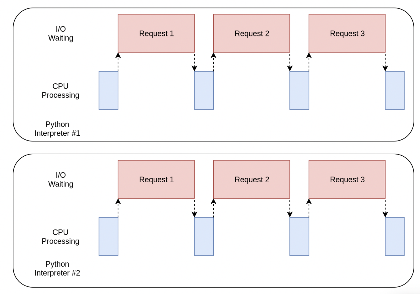
There are a few different ways to do concurrent and/or parallel programming in python. This
post gives a good overview with diagrams time diagrams for each process.
The most important things to grasp is that vanilla python is in no way built for parallel processing because of
the Global Interpreter Lock (GIL), which ensures that each python instance operates in one thread at a time.
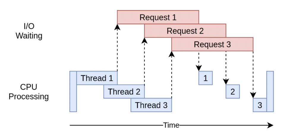
Creates multiple 'threads' which can run at the same time. However, it doesn't break outside of the
GIL, so only one thread can run at a time.
Thread prioritizing is left up to the OS, outside of the programs/programmers control, so the same code can
return different results and caution must be taken when referencing the same variable from multiple threads.
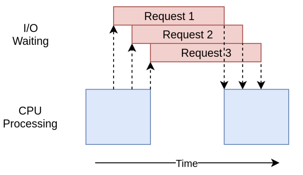
Asyncio is basically the same as threading (it's built with the same low-level coroutine pass off),
but instead of creating mulitple threads of separate I/O requests, the requests are sent from the same thread
and the programmer cnotrol when a task is waited on with async/await commands. This has an additional speed
optimization because you dn't waste time spinning up and down a ton of threads, but still get the concurrency win at the expense of needing to optimize design planning.
Multiprocessing is the library you use for true parallel processing in python, it spins up mulitple
python instances to have one GILs for each CPU and is therefore best fit for computationally instensive parallelism.
It's not great for I/O concurrency because it takes a lot of time to spin up all the GILs.
race condition debugging
My problem is complicated because I need multiple threads to run long toolpath commands
and I need them all to share the websocket, which requires asyncio. So I need a blend of
asyncio and threading, which requries careful details to thread safety and something keeps
going wrong . . .
I've tried to get rid of threading and just pass the websocket into the Laser and Stage class, but
that doesn't work because the websocket needs to be asynchronous and tool path commands cannot be
sent asynchronously.
I've tested just the websocket,
then just the threading,
then threading and websocket without the machine. All seem to work as they
should without mysterious race conditions. But the problem persists when I move it to passing values from Stage and Laser.
The most promisng solution so far, here,
is to run three different asycncio loops in a threadPool with the consol print written to a queue.Queue() (not asyncio.Queue()). It works properly
when the stage and laser classes are replaced with timer delays, like
this test, but
there are still bugs when running on the Pharos.
At this point, I've wasted weeks on this bug and in the final hours of the final project, I need to move on
to actually laser machining, so I made a new branch (no-console) with a work around.
Instead of streaming the console output to the client, it's just printed in the terminal. That way, we only need one asyncio thread with a consumer / producer handoff and everything
works pretty well.
laser characterization
questions to answer:
What is the laser spot size?
Is the camera focus point aligned with the alser focus point?
Laser parameters to vary:
laser power
pulse repetition rate
scanning speed
focus offset
Results to quantify, and the tools they can be measured with:
ablation depth (confocal, AFM?)
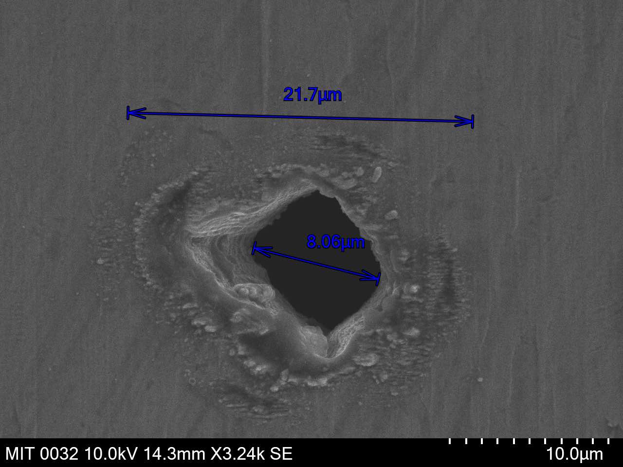
kerf (SEM)
surface roughness (SEM)
material removal rate (abaltion depth / machining time)
I didn't set up the optics for the beam delivery system so their alignment is unknown, but
I also don't want to mess with them because bumping the wrong things could be a day+ of work
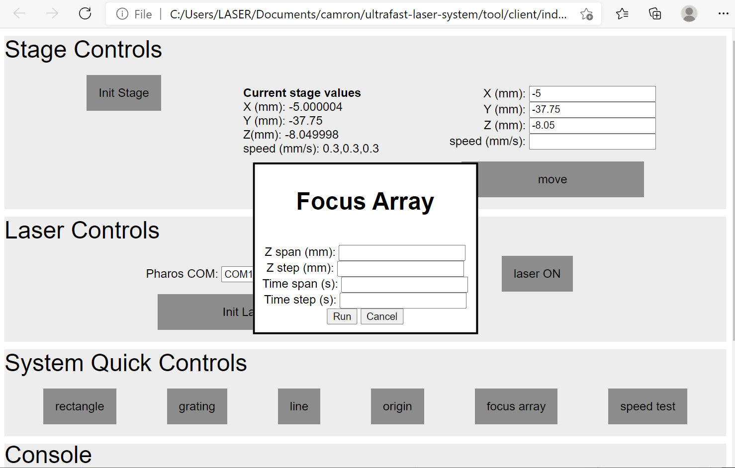
to readjust. A major uncertainty I've had is whether or not the camera focus point is aligned
with the laser focus point. To test this I added a `focus array` command to the GUI to turn the laser
on and off at varying z heights. The z height varying along x, and the amount of time the laser is
turned on varys along y.
After testing this on different material, it became clear that the z position needs to be
increased by about 300um from the camera focus to align best with the laser focus. How can
I adjust this mechanically instead of account for it in the stage postiion?
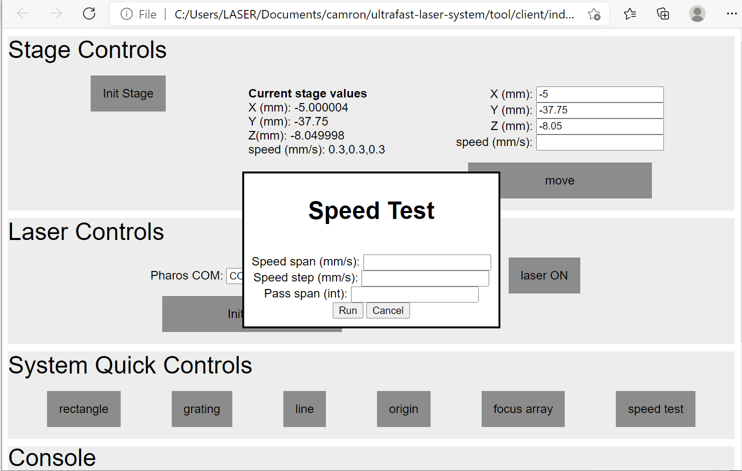
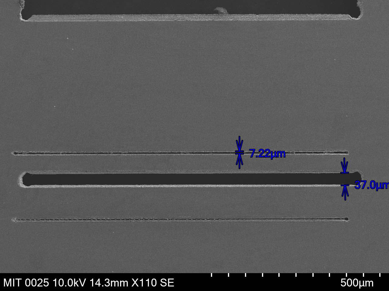
speed optimization
To find the right speed and feed setting, I also set up a similar loop test for
machining 1mm lines at different speed and a range of passes. This is the
speed test command.
However, this didn't work as well because the machining sample isn't perfectly flat
and the slightest change in z makes a big difference in the line width so I did most of the line
testing manually and will need to figure out a better way to mount thin sheet samples.
table wobble
The floating table isn't floating very well.
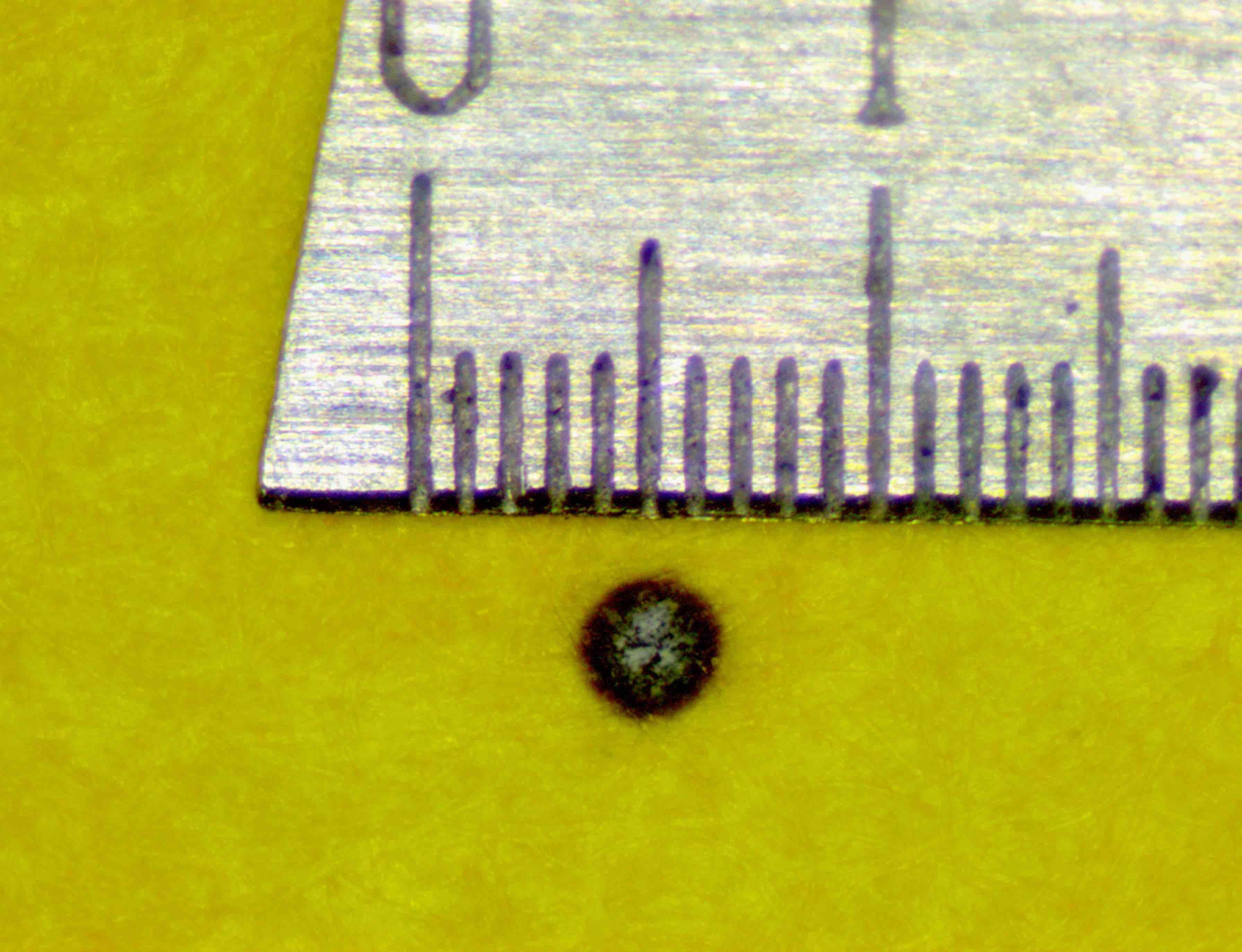
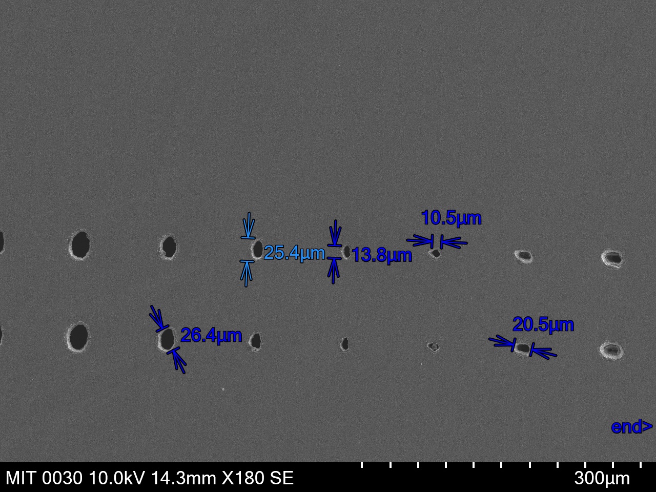
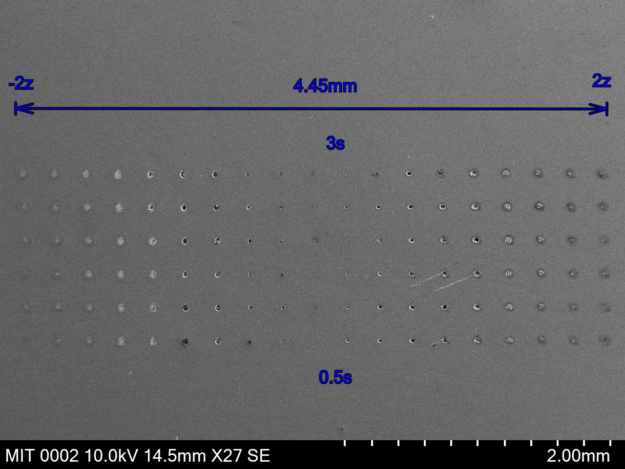
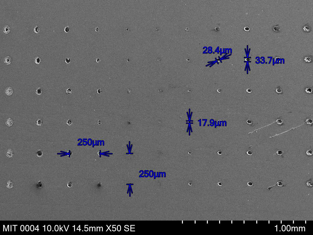
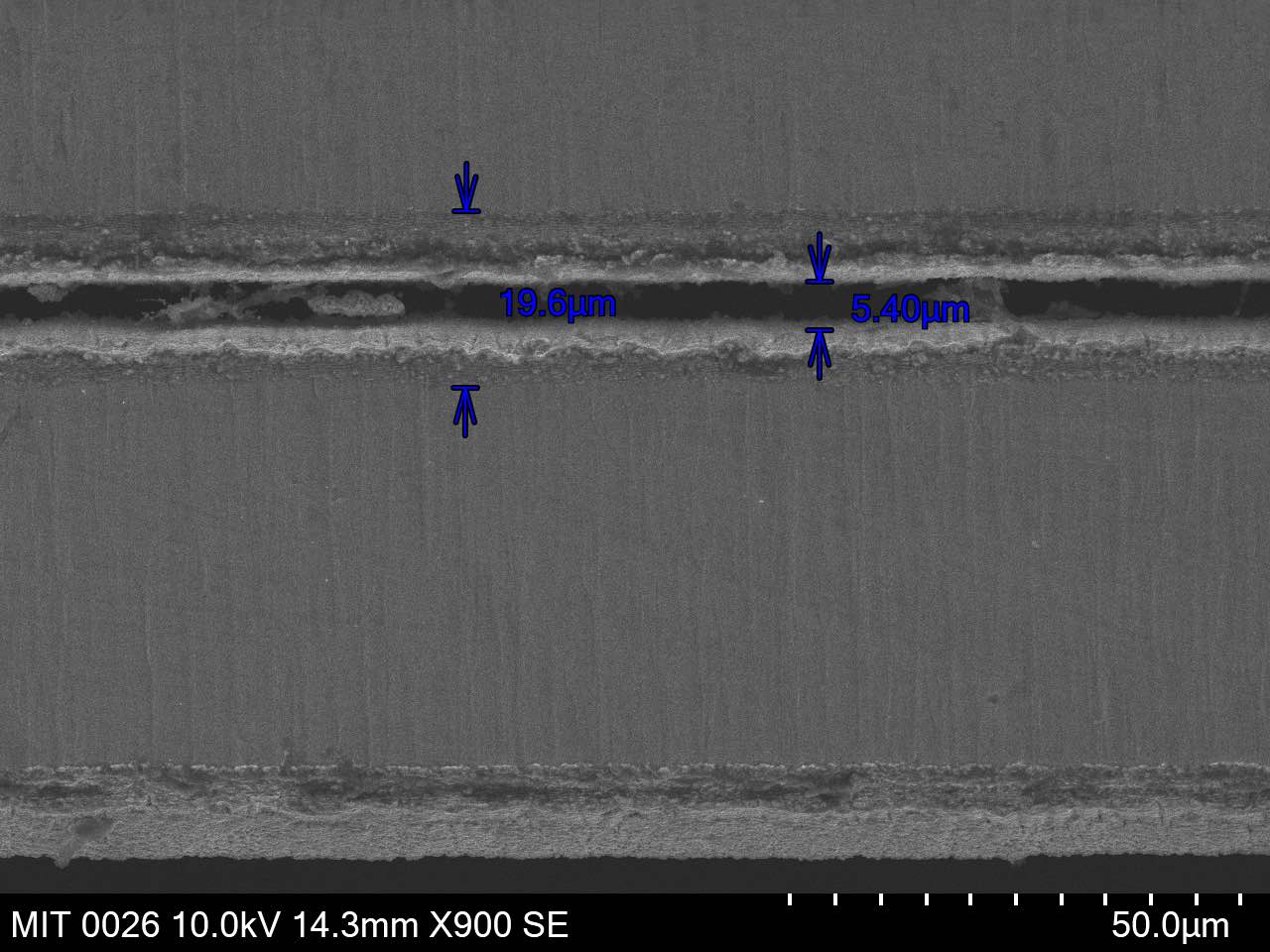
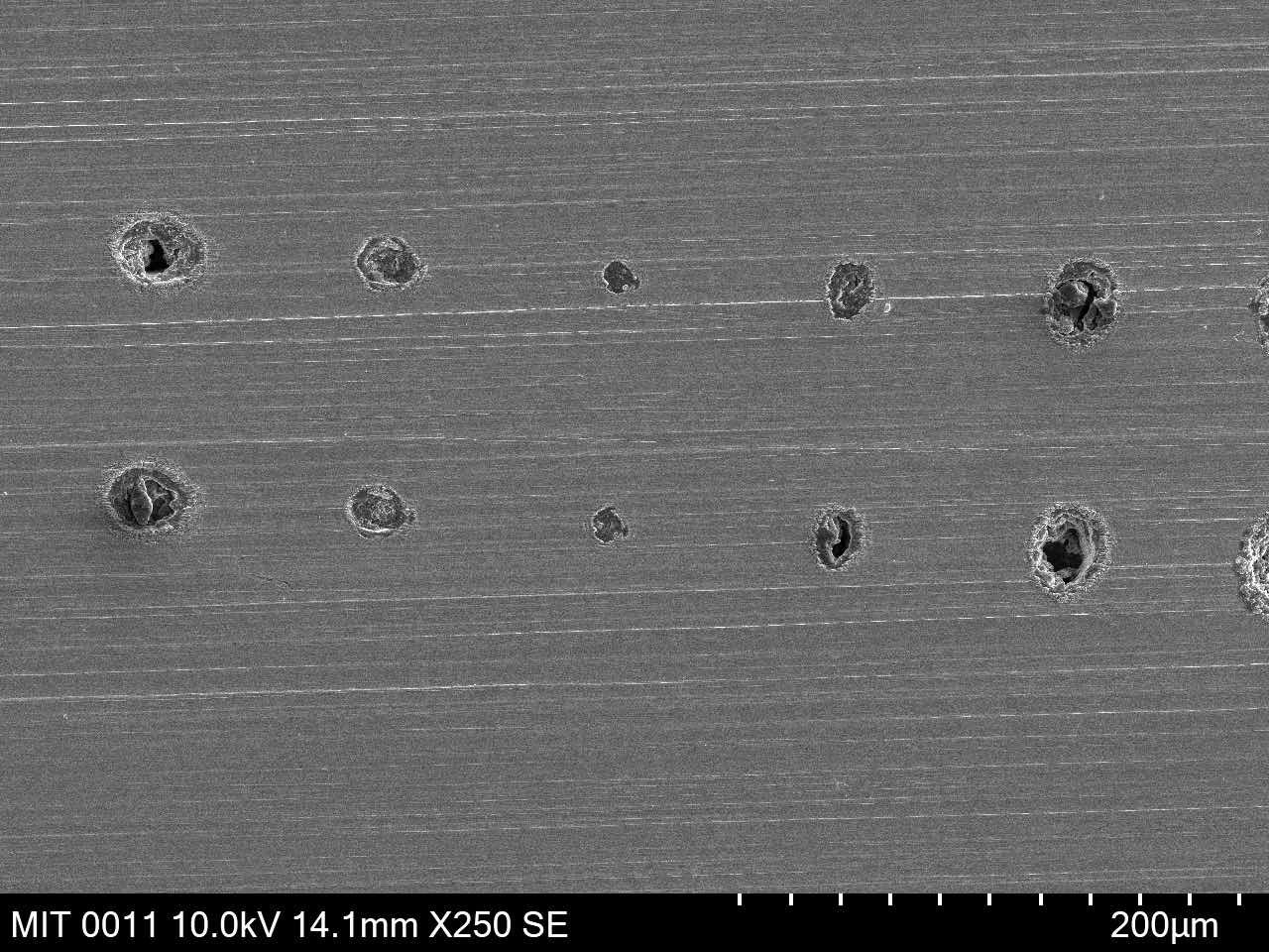
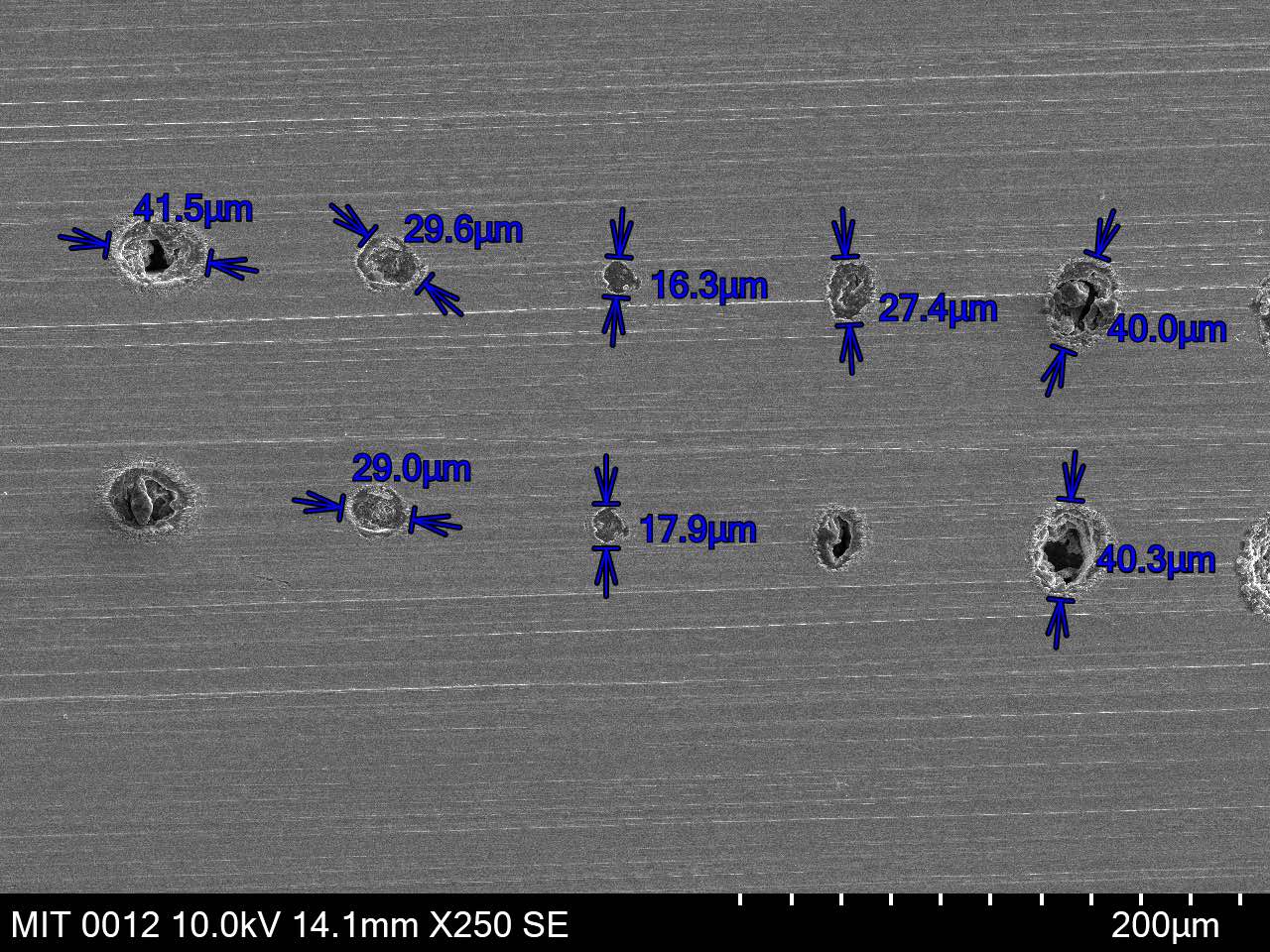
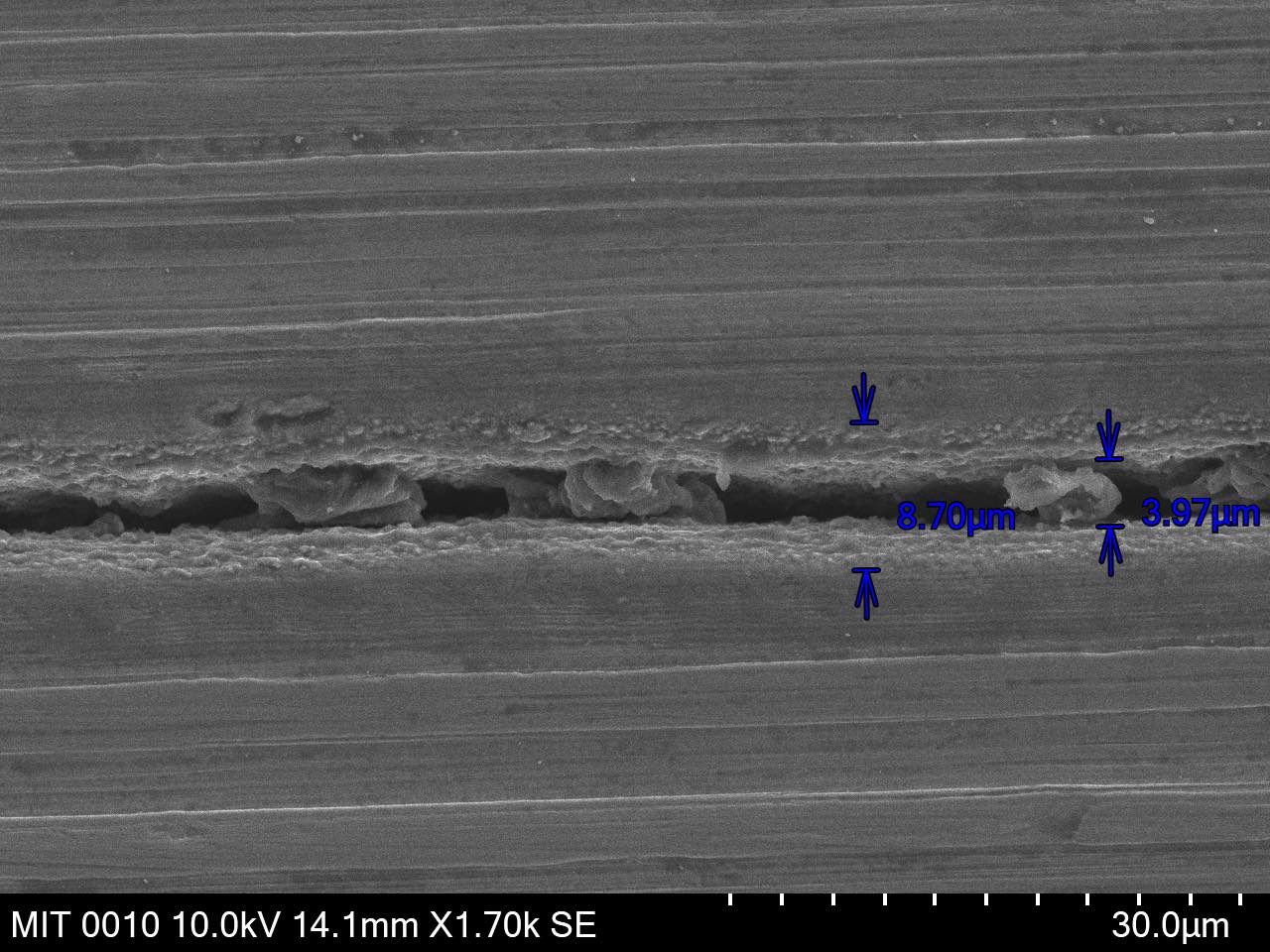
material testing
0.0005" stainless steel
0.0005" stainless steel shim stock with 10X objective lens
The top row had the laser on for 0.5s and the bottom for 1s.