MicroMachines
diffraction gratings
background
first attempt
diffraction gratings
I'm not sure they reaally count as micromachines on their own . . . but
they are a good starting
point to wake up initial applications with the system.
background
Diffraction gratings are a workhorse in most fields of experimental
science and engineering due to their crucial in high precision and accurate
spectroscopy.
Gratings provide a spatial modulation to the refractive index of incident
polychromatic light which causes it to desperse into it's
monochromatic components.
There are reflection gratings, where the diffracted rays are on the same
side as the incident light, and tranmission gratings, where the diffracted
rays are on the opposite side of the incident light.
There are a few different kinds of gratings - ruled gratings, holographic
gratings, and replicated gratings:
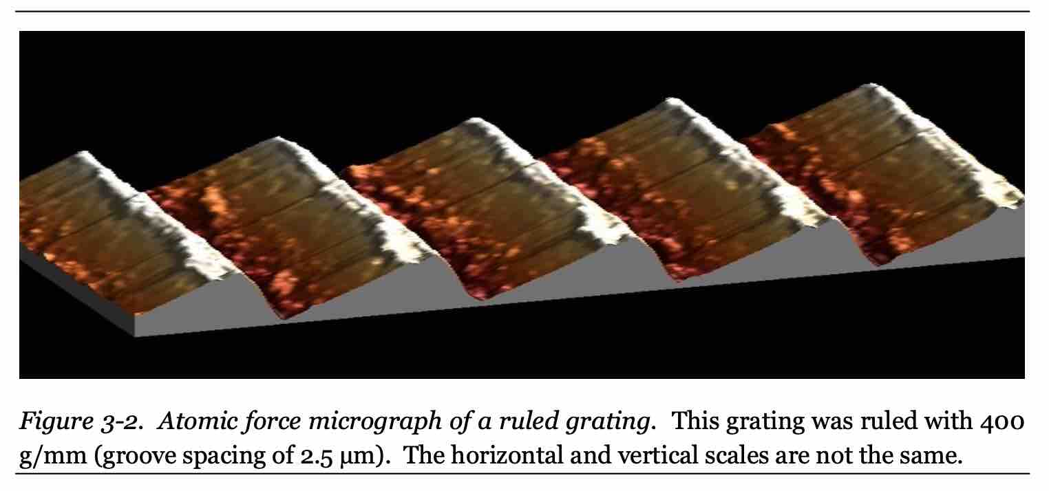
ruled gratings
Ruled gratings are mechanically manufactured by burnishing individual
grooves into a thin coating of evaporated metal applied to a plane or
concave surface using a diamond tool of specific shape for specified groove
profiles.
This process is done with Ruling Engines :
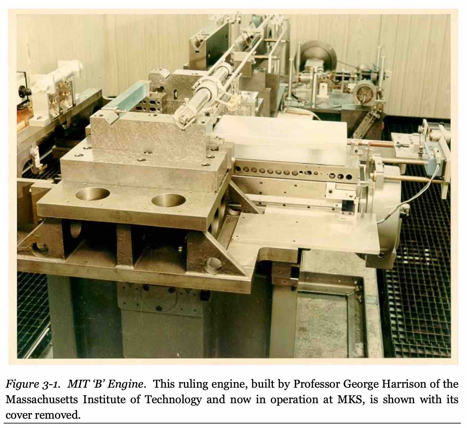
ruling engines give precise control over the groove profile for each
grating.
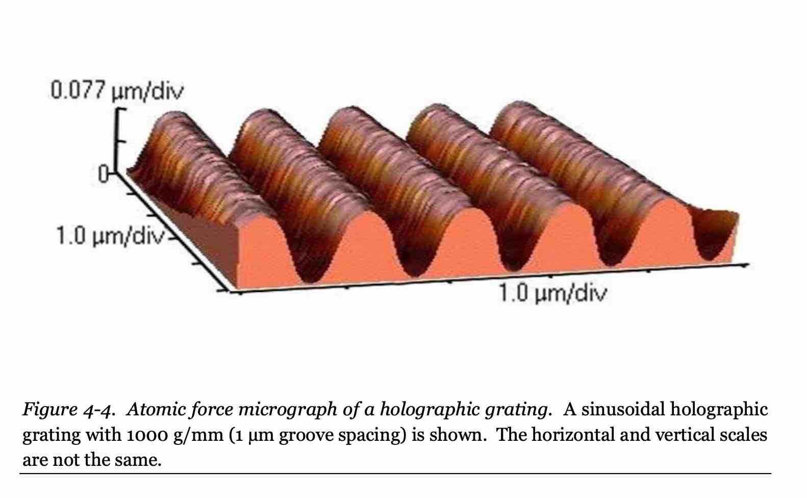
holographic gratings
Holographic grates are fabricated using a photolithographic process. The
standing wave interference pattern of two equal monochromatic plane waves
are used to imprint a pattern on a photoresist layer.
Holographic gratings have a sinusoidal groove pattern which is less
efficient than ruled gratings.
holographic gratings are generally more reistant to surface irregularities
than the mechanically ruled gratings since all of the grooves are made
simultaneously as opposed to serially. Therefore, they scatter less light
are are prefered in systems where stray light can introduce noise.
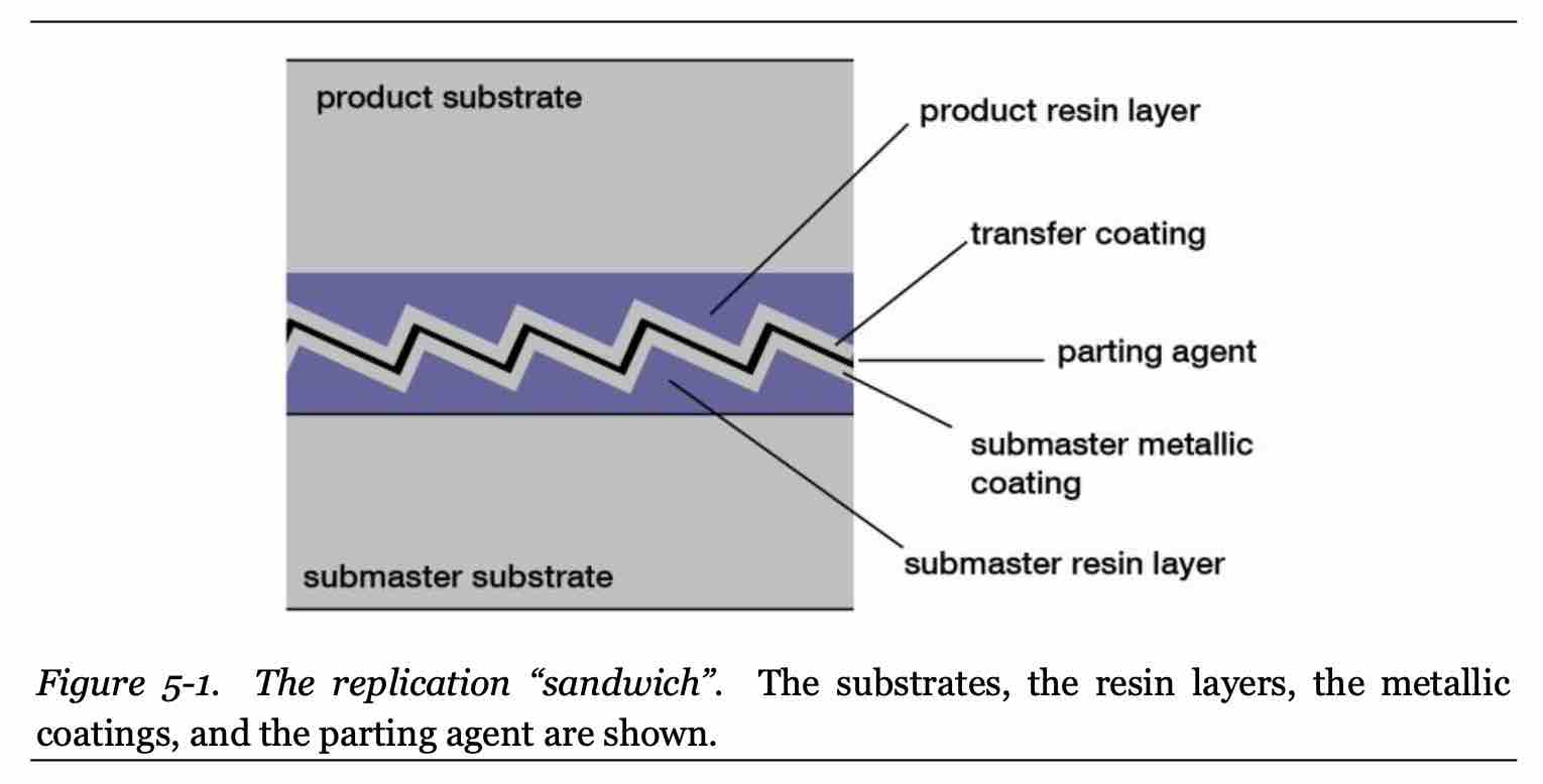
replicated gratings
Replicated gratings are those which are "replicas" of master gratings
manufactured by mechanical ruling or holographic recording. They are a high
precision casting and molding process
Master gratings are typically made on well-annealed and high polished
(lambda/10 surface finished)
substrates of optical glass or fused silica and coated with aluminum or
gold.
Varied line-space (VLS) gratings sound difficult to produce on a grating
engine, but could be easy for the laser setup.
first attempt at fabrication
Most ruled diffraction grates are made by using a diamond microtool to
carve away a thin layer of refletive coating from a substrate. To try to
mimic this process with a laser, I atempted etch the grating pattern into a
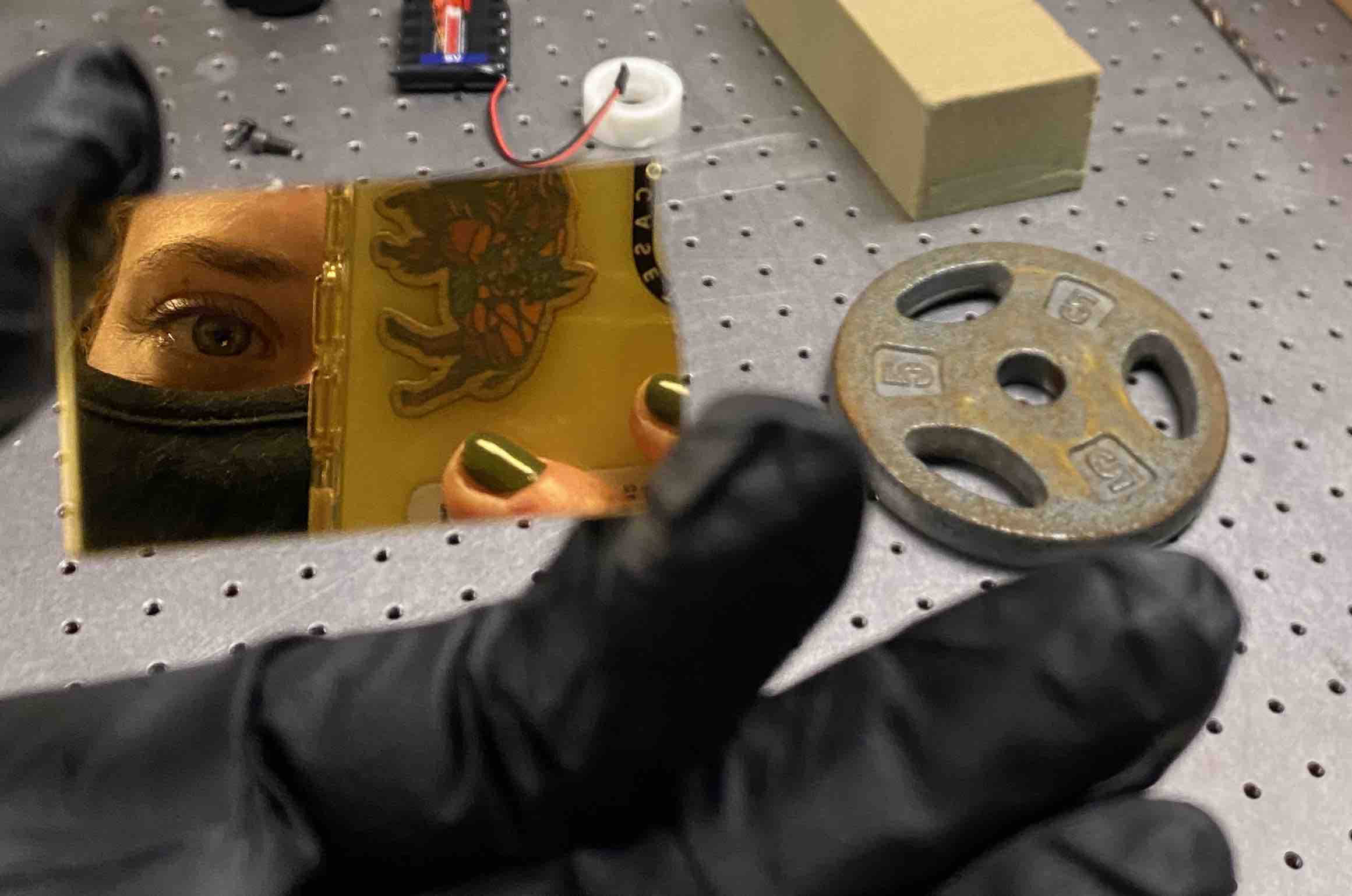
layer of gold on a microscope slide.
I sputter coated a 200nm gold layer onto a glass slide
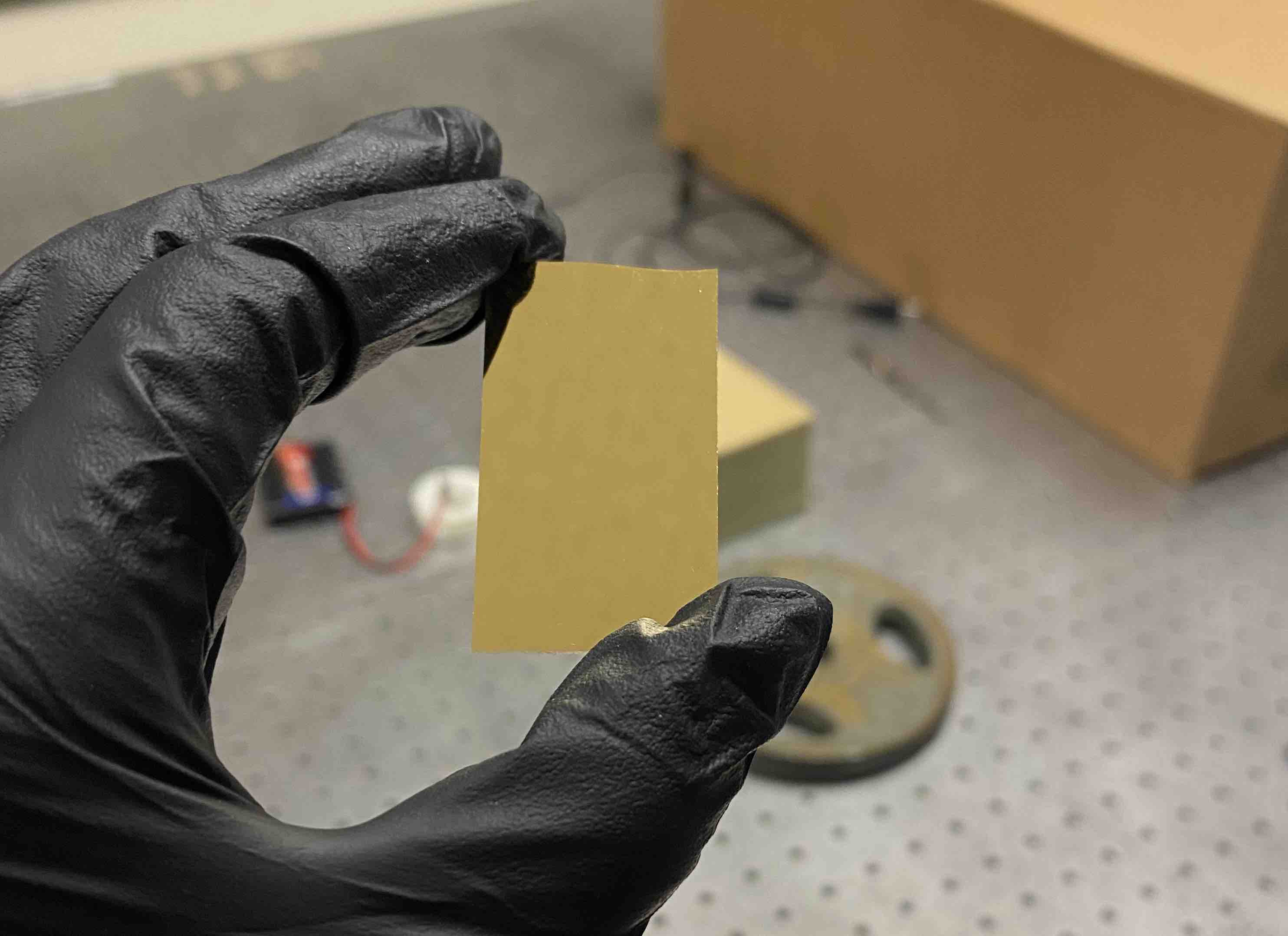
it's sufficiently reflective :)
Then I wrote a quick script for generating a diffraction gratting pattern
given the total length and width and the distance between gratings - here.
If this works, it will be integrated into the web app with more robust
control over design parameters.
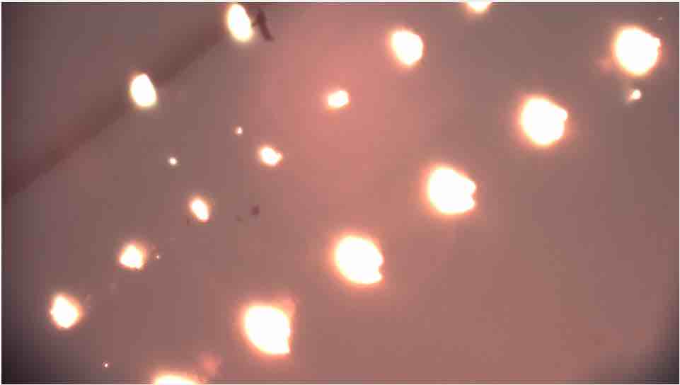
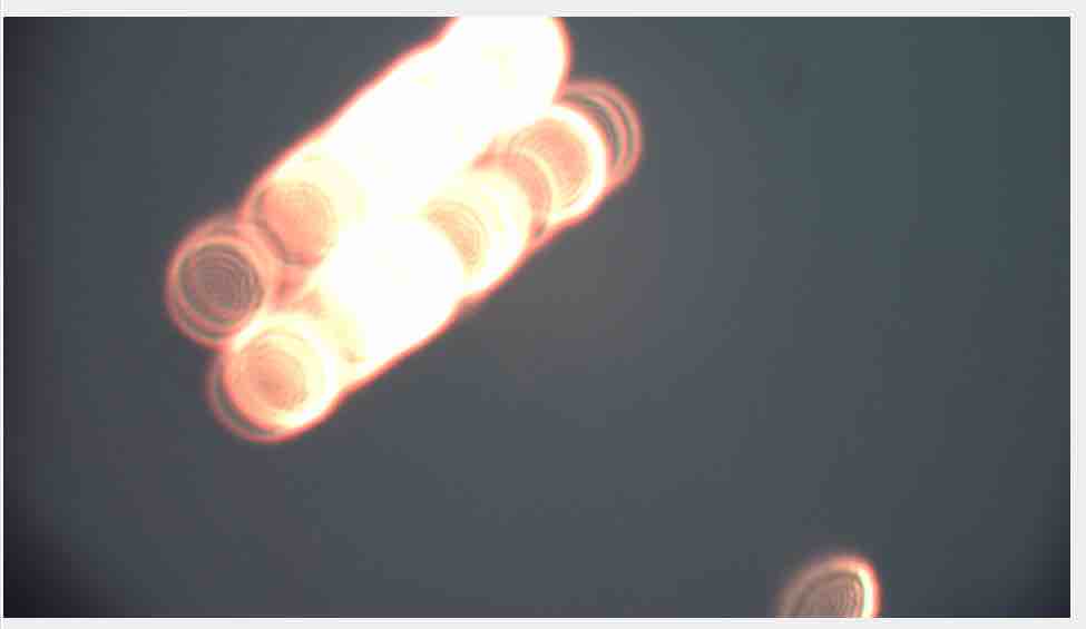
Focusing on the surface of the gold slide was tricky because it's easy to
accidentally focus on something below it. After I got the camera properly
focused on the surface of the slide and turned on the laser, I couldn't see
any sign of the laser. I think this is due to the offset between the laser
focus point and the camera focus point. I scanned along the z-direction
with the laser on until I saw the spot appear on the camera. There was a
range of about 1.5mm where the laser (at 532nm) was visible and it was
about 2mm above the camera focus. Here is an example of the range of spot sizes I saw
while testing the z position with the laser on
I chose a small-ish spot size (z=-11.59mm) and tried testing the grating toolpath with
a 1mm by 0.5mm rectangle with 4 grooves/mm (250 um between grooves) with
the stage moving at 100um/s
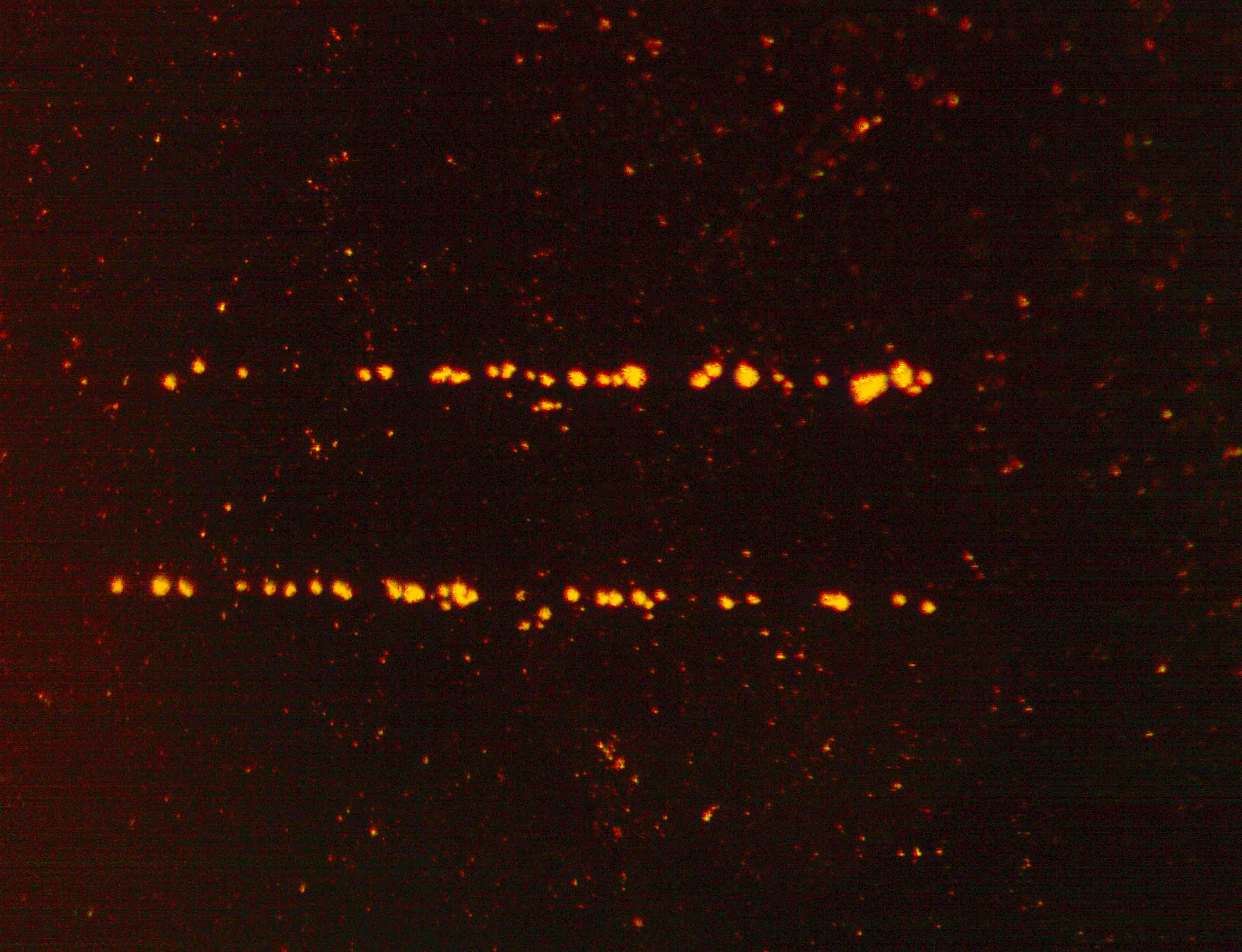
The results looked like the grooves overlapped a lot and it wasn't a
consistently machined line. But the image is misleading because the camera
is significantly out of focus. After taking the slide out of the laser setup
and imaging it separately, you can see that the gratings were very far
apart and the gold was not removed uniformly as the stage moved.
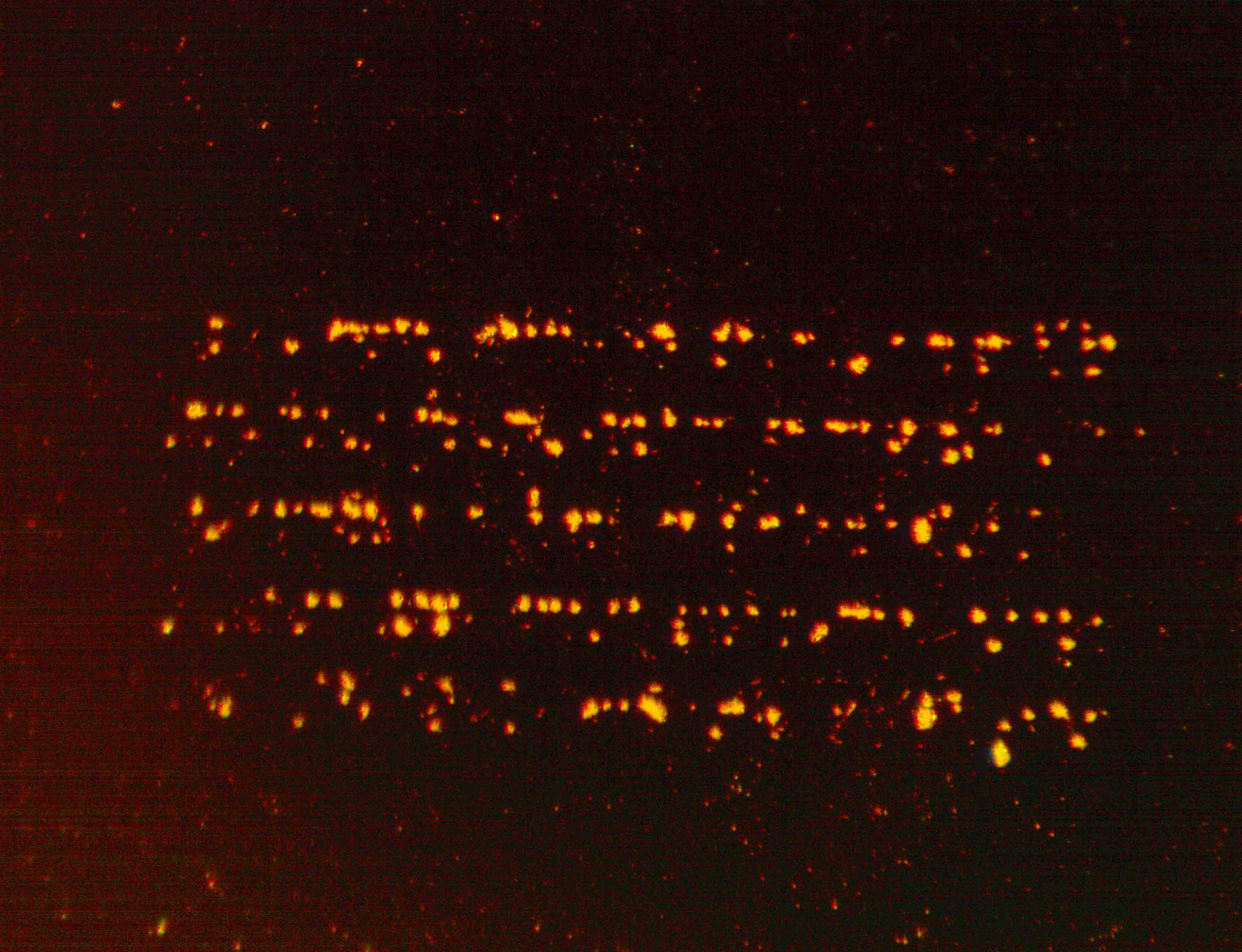
I also ran another test with 10 grooves/mm at an even smaller laser spot
size (z=-12.19mm) and 10um/s speed. The result was still speckled although the
grooves were distinct.
With a better idea of what's happening to the gold layer, I did another run
at a much larger spot size (z=-10.98mm), 10 grooves/mm, and 5um/s stage
speed. This was a dramatic over correction.
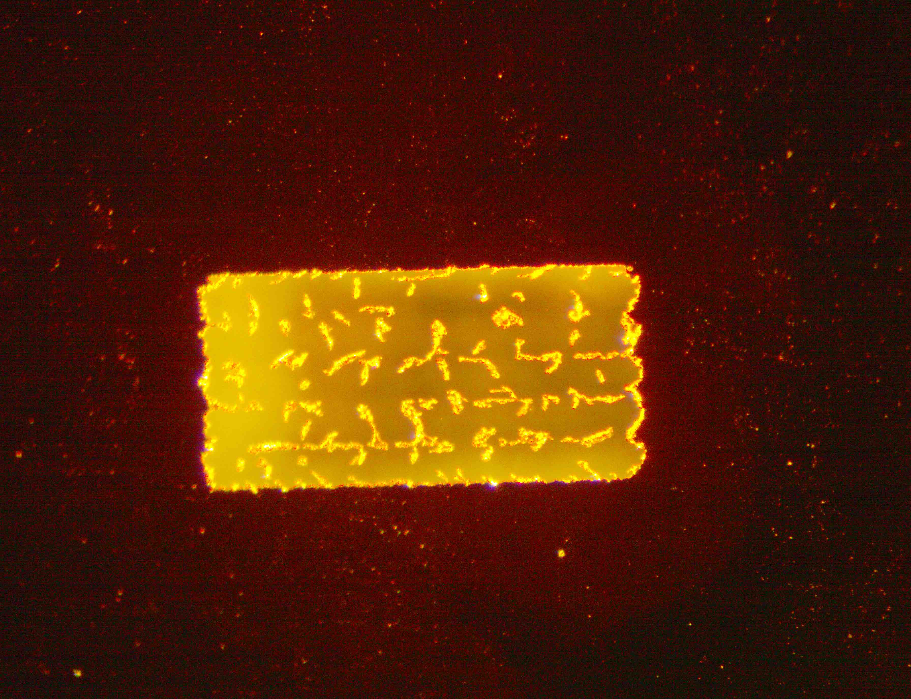
more parameter tuning to come . . .