<br>
[Back to course page](https://fab.cba.mit.edu/classes/865.21/)
***
<a name="index">
</a>
# Jens Dyvik's page
- [About me](#about-me)
- [Component](#component)
- [System](#system)
- [Bonus metrology project](#bonus)
- Log:
- [Week 2](#week2) - defining a component and a system
- [Week 3](#week3)
- [Week 4](#week4)
- [Week 5](#week5)
- [Week 6](#week6)
- [Week 7](#week7)
- [Week 8](#week8)
- [Week 9](#week9)
- [Week 10](#week10)
- [Week 11](#week11)
- [Week 12](#week12) - last developments and prep for final presentations _(WIP)_
- Final outcomes:
- [H-axis - flexure version](https://fab.cba.mit.edu/classes/865.21/people/jensdyvik/h-axis-flexure.html) _(parametric DIY axis for light duty small scale machines)_
- [H-axis - linear rail version](https://fab.cba.mit.edu/classes/865.21/people/jensdyvik/h-axis-linear.html) _(parametric axis for heavy duty small large machines)_
- [H-axis - v-wheel version](https://fab.cba.mit.edu/classes/865.21/people/jensdyvik/h-axis-v-wheel.html) _(parametric DIY axis for medium duty medium scale machines)_
- [Pellatis pellet extruder](https://fab.cba.mit.edu/classes/865.21/people/jensdyvik/pellatis.html) _(DIY pellet extruder aiming to output 1-1.5kg of PLA per hour and combine with continuous natural fiber)_
- **Update March 2024:** [Hanzo](https://github.com/Fabricatable-Machines/Hanzo), the H-axis based large format 3D printer, milling machine and research platform, became operational autumn 2022 and is still in use. Project repo [here](https://github.com/Fabricatable-Machines/Hanzo).


<a name="about-me">
***
</a>
# About me
### Core projects
I create open tools for global collaboration and local manufacturing. Some of my core projects are:
- [Fabricatable Machines](https://github.com/fellesverkstedet/fabricatable-machines/wiki) - a system for building custom digital fabrication machines with a high degree of self fabricated parts. This [paper](https://github.com/fellesverkstedet/fabricatable-machines/raw/master/publications/Fabricatable%20Machines%20-%20A%20Toolkit%20for%20Building%20DigitalFabrication%20Machines%20-%20TEI202.pdf) from the project was published at TEI202
- [Bark Beetle](https://github.com/fellesverkstedet/Bark-beetle-parametric-toolpaths/blob/master/README.md) - CAM for creating CNC milling toolpaths with Rhino and Grasshopper and embedding in parametric objects
- [Making Living Sharing](https://drive.google.com/file/d/1geu_GuJQz8S8bz9bmdWiVUWyAENWw7ce/view?usp=sharing) - a 40min research documentary on open design, global collaboration and local manufacturing
### Motivations
I am a strong believer in reducing artificial scarcity in all domains of human life. Collaboration and "the greater good" argument of openly published research, design and software are very important to me. I believe that the majority of human challenges on earth are caused more by mental issues and interhuman relations, than a lack of technological progess and inventions. By contributing to making digital fabrication and self fabrication of custom automation equipment more available _(both practically and mentally)_, while contributing to global knowledge sharing, I hope to help more people follow their dreams and feel more connected to humanity. I also hope to contribute to reducing the digital divide and rising inequality in wealth distribution.
I explore methods for making as many parts of a machine as possible in a simple way, for both sport and rational reasons. The rational is about designing machine systems that can be fabricated and assembled with a high degree of automation. And make machine building more available in places where import of exotic hardware such as alu extrusions, linear rails and timing belts is expensive and time consuming. The sport part is about the self satisfaction, self image building and the learning curve that comes from making critical components of a machine such as a linear axis and drive system yourself.
I consider myself more of a translator than inventor. Similar to how one might translate latin text to a common language in order to make history available, I translate cornerstone technical inventions into fabricatable designs _(rack and pinion, rails, machine frames etc. you can actually make yourself)_.
### Work
I am not employed by an academic institution or company, but work independently while collaborating informally with many peers. I aim to increase the time spent doing this work and its impact with the help of my freshly launched [Patreon page](https://www.patreon.com/jensdyvik).
I am a former fab lab nomad and a co-founder of [Fellesverkstedet](https://www.fellesverkstedet.no/facilities) one of the worlds most comprehensive independent Fab Labs.

_Thats me. (Photo by: Svein G. Kjode)_
### My role in MAS.865.21
I am honored and excited to have been invited to sit in during the 2021 winter/spring class of _How to Make Something that Makes (almost) Anything_. I am available as a resource, but also aim to do the assignments.
I have recently started renting a 21m2 studio _(in the building of Fellesverksted, the Fab Lab that i co-created in Oslo, Norway)_. Inside this studio am building a cartesian reserach platform with a roughly 7m3 work volume. The machine will have a heavy-duty tool changing system to allow me to experiment and develop new fabrication workflows, while understanding more about automation. My three main research areas are:
- Making large format digital fabrication more accessible
- Making sustainable materials and local material loops more accessible
- Making automation more accessible _(combining additive and subtractive manufacturing, pick and place with grippers/vacuum, automatic loading of stock and packing of finished parts and lots more)_
I plan to use this course to boost the development of this large dream research platform machine and benefit from the exchange of insights and best practices with fellow machine builders.

_My old Motoman robot arm running 6axis Bark Beetle CAM that I programmed in Grasshopper, with some of my Fabricatble machines prototypes to the left. (Photo by: Svein G. Kjode)_

_Me whispering to the ShopBot sacrificial layer at the old location of Fellesverkstedet, the Fab Lab i co-created in my hometown. (Photo by: Svein G. Kjode)_
[Back to index](#index)
<a name="week2">
***
</a>
# _Log:_ Week 2, February 25th-3rd of March
<a name="component">
***
</a>
# _Component:_ A continuous fiber nozzle for pellet based extruders

### What
- A nozzle that accepts fibers like flax or hemp thread and co extrudes with a polymer like PLA
- A servo driven cutting knife
- A thread feeding mechanism
- A spring loaded spooling system
- Possibly sensors for detecting yarn over tension and run out
- A custom CAM solution of planning when to snip the thread and also merge rough 3D printing with finish machining
### Why
- If we can mix PLA with natural fibers like flax we can get very high performance freeform parts that can be industrially composted at the end of their lifetime. The goal is to have fabrication processes with a smaller environmental impact and local recycling loops.
- I hope discarded composite flax and PLA parts cen be shredded and extruded again with more flax. Increasing the fiber content and reducing the environmental impact. _(New continuious fiber together with short old fiber)_
- If the 3D printed parts have higher performance we can can be less reliant on stock of exotic materials for machining like aluminum and phenolic resin composite sheets.
### How
- Machined brass?
### Files
- A rough first sketch here: https://gitlab.cba.mit.edu/classes/865.21/site/-/blob/master/people/jensdyvik/cont-fiber-nozzle.FCStd
### Relevant prior personal work
- A quick test I did mixing additive and subtractive on a self designed and made Fabricatable machine https://youtu.be/p09yLGG0fSc
- [Homepage](https://tobben.gitlab.io/pellatis/dev/update/2021/03/04/adapter-plate-machined.html) and [repo](https://gitlab.com/tobben/pellatis) of a pellet extruder for Fabricatable machines and Hangprinters that I am currently developing in collaboration with Torbjørn Ludvigsen.

_I milled the alu bracket for the Pellatis extruder in February 2021_

_Exploded assembly. We use a cheap NMRW30 gearbox not only for gearing, but as the frame of extruder and thrust bearing. Naughty, but too tempting to not try._

_The current state of the extruder on march 4th 2021_
### Relevant research
- [Three-Dimensional Printing of Continuous Flax Fiber-Reinforced Thermoplastic Composites by Five-Axis Machine ](https://www.mdpi.com/1996-1944/13/7/1678) Open access resarch article with promising results with PLA and flax fiber
### Relevant open source work
- https://mahor.xyz/
- https://github.com/Bloft-Design-Lab/Bad-Ass-Pellet-Extruder
### Relevant closed source work
- [Mark forged](https://markforged.com/) Filament based extrusion with carbon fiber
- https://massivedimension.com/products/mdphe-v1-pellet-head-extruder-system
- https://dyzedesign.com/pulsar-pellet-extruder/
[Back to index](#index)
<a name="system">
***
</a>
# _System:_ A cartesian toolchanging research platform with a 6m3 work volume

### What
- A cartesian machine with a 3m x 1,5m x 1,4m work area
- With a toolchanger system
- With dual pinion drive for electronic pretension _(less backlash, higher cost and complexity)_
- Tailor made to experiment with automation and machine making
### Why
- I need a large machine with a lot of flexibility to do the research that I wont to do the coming years
- If I have machine with a 3m long work area I can make machines with a 2,44m work area _(standard sheet size)_ for my local community in a single piece
### How
- I am looking to CNC mill almost all the the parts _(frame, rack, rails)_ from 12mm thick Trespa or other phenolic resin paper composite sheets
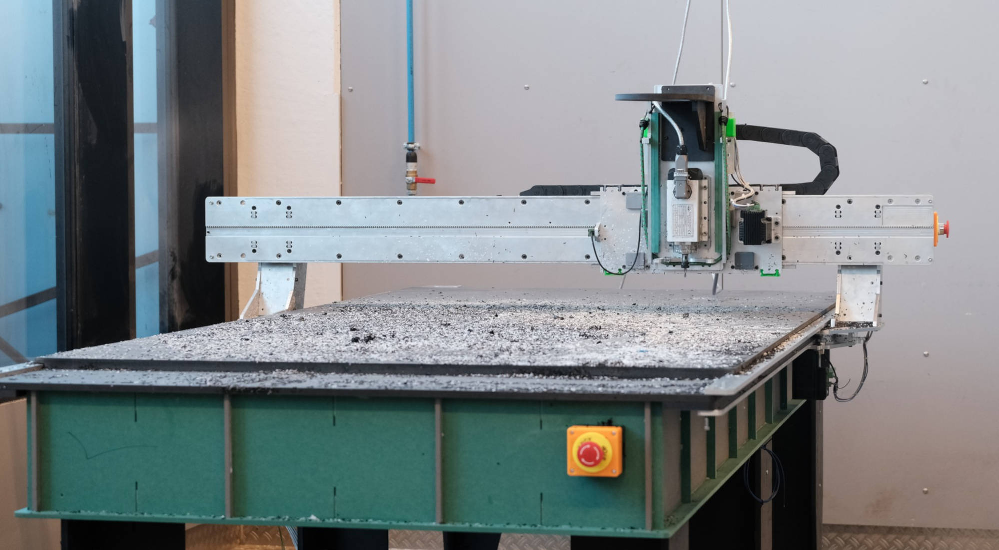
- In order to make the longest axes in a single piece I am going to machine it diagonally from a 3m x 1,5m piece. I will be trading access to ShopBot alpha 120-60 against calibration service and maintenance training _(one of the power users of our FabLab got super hooked on the ShopBots and took the plunge and bought his own extra large ShopBot)_
### Files
-A rough first sketch here: https://gitlab.cba.mit.edu/classes/865.21/site/-/blob/master/people/jensdyvik/hans-large-format-research-platform.FCStd
### Sketches

_Using freecad skecth solver to find the longest possible rail with specified center line distance and edge distances. This reference constraint is used further in making an axis tailored to the available stock_

_Force loop during milling to the right, and during 3D printing to left. It is a deliberate compromise to have an increasingly weaker machine the higher up along the Z axis it works. I am slightly worried about ressonance in the towers though_

_Sketch side view_

_Sketch top view_

_Sketch front view_

_My original plan was to use linear rails on rectangular steel tubing, with possibly leveling them falt with gravity casting a 5mm epoxy layer. Here is the first 1:1 test sample I made_

_I used freecad to visulize different locally availble steel beams with different rails_

_This was my main plan in January 2021, until i realized that would have to drill and tap about 900 holes in total for that. I has some smart plans for making it faster and easier to drill the holes, but still...._

_So sketched out an alu extrusion based version with extrusions from Tuli shop. It is very sane, but quite expensive and boring. Just the extrusions alone was about 1700EUR ex VAT. And still about 900 t-nuts to place accurately. During Neils first MAS 865.21 lecture I got inspired to try to make the machines with Fabricatable axes_
### Relevant prior personal work
[](https://youtu.be/aQdFYgx5cQA "Axis demo")
- DIY linear rail https://github.com/fellesverkstedet/fabricatable-machines/tree/master/Module%20development/linear_guide

- CNC friendly rack and pinion https://github.com/fellesverkstedet/fabricatable-machines/wiki/Modules#cnc-friendly-rack-and-pinion
- Humphrey large format CNC https://github.com/fellesverkstedet/fabricatable-machines/blob/master/humphrey-large-format-cnc/README.md
### Relevant open source work
- https://e3d-online.com/pages/toolchanger
- https://github.com/machineagency/jubilee
### Relevant closed source work
- https://piersonworkholding.com/mini-pallet-system/
- https://www.staubli.com/en/connectors/tool-changer/
- https://www.ati-ia.com/products/toolchanger/robot_tool_changer.aspx
[Back to index](#index)
<a name="bonus">
***
</a>
# _Bonus metrology project:_ Simple methods for measuring deviation in self built machines
- Water bath and conductive needle probe for comparing machine bed to gravity plane
- Milling straight sections along an axis, flip it and register with dowel pins and probe the difference. Done independently for X and Y
[Back to index](#index)
<a name="week3">
***
</a>
# _Log:_ Week 3, 3-11th of March
### New axis type, H-axis
I have started building a parametric axis generator. I used a principle of construction that I thought of some months ago. Here are the tricks:
- The rails and the mating surfaces are milled next to each other. If the bed of the CNC mill is uneven, the unevenness of the v rail will be matched by the mating surface/pocket next to each other.
- When the parts get tightened together the rail will deform slightly, becoming as straight as the horizontal part they screw into.
- Like this we only need to worry about lack of straightness in the X and Y direction on the mother machine not Z.
- I have started work on how to map X and Y deviation on a machine and use this deviation map compensate in Bark Beetle CAM
- The rack is milled into the same part as one of rails, taking care of alignment in all directions and no assembly is needed.
- All the tapped holes are in the Z direction during machining. So the holes can be thread milled by a simple 3 axis machine like a shopbot. No drilling and tapping and no placing hundreds of t-nuts into alu extrusions
Next up is fabbing a test axis when my Formica compact sheet arrives.
File:
- https://gitlab.cba.mit.edu/classes/865.21/site/-/blob/master/people/jensdyvik/h-rail-axis.FCStd

_Early work in progress_

_The v-rail upper lip felt a bit fragile and the part protruding from the lower pocket redundant_

_This improvement feels better. It might be a bit more complicated to have two rail types, but I do think that this rail config is stronger and slightly more dust proof_

_Machined surfaces in pink, untouched in white. I am quite pleased with how easy this makes it to make opposing v-rail without special tools or techniques, and flatness of the mother machine bed is maybe much less of an issue than before_
### Helical rack and pinion
A few months back I had the epiphany that helical involute racks can be matched to the angle of a common v-bit type _(60deg for a 30deg pressure angle)_. Classic rack and pinion I believe have a pressure angle of 20 degrees. The 40 degree v-bit required to mill this quite exotic and not so easy to source.
Next up is testing a 3D printed pinion on a phenoilic resin wood fiber composite rack.
File:
- https://gitlab.cba.mit.edu/classes/865.21/site/-/blob/master/people/jensdyvik/helical-involute-rack-and-pinion-for-milling-rack-with-60deg-vbit-and-fdm-print-pinion.FCStd

_With 12 teeth on the pinion and Module1 size teeth the distance traveled per revolution is abou 40.12mm, good enough for driect drive without gearbox in many applications_

_Note how the 60degree Vbit matches the 30deg pressure of the rack. Super easy to fabricate with a standard type V-bit. Alignment and mounting is solved with the H-axis approach described above_

_First test print. It rolls very smooth, also with a lot of pressure by hand._

_I am considering to make a GT2 timing belt gearbox_
### CAM Tapping
One of the lessons learned from assembling the [Humphrey](https://github.com/fellesverkstedet/fabricatable-machines/blob/master/humphrey-large-format-cnc/README.md) large format CNC machine was that drilling sideways into the alu parts and tapping by hand takes a lot of time. I am trying to optimize the H axis so that longer screws go across the axis, allowing the threads to be CNc milled and tapped by the same CNC machine that makes the parts. No need to drill and tap by hand, or insert square nuts into slots.
So I developed a thread milling feature for my self made CAM program, [Bark beetle](https://github.com/fellesverkstedet/Bark-beetle-parametric-toolpaths/blob/master/README.md). Having full control on this in my own CAM intead having to move to Fusion360 or V-Carve makes extra sense, since I am slo working on automatic componesation of unstraight axes in CAM _(see next log chapter bellow)_
File:
- In the [Bark Beetle repo](https://github.com/fellesverkstedet/Bark-beetle-parametric-toolpaths/blob/master/Development%20files/Internal%20thread%20milling.gh)

_The helical toolpath is quite easy to make. The most important part is to ensure that the milling bit exits from the center of the hole, in order to not ruin the sides_

_This type of thread milling bit is quite cheap and easy to source. This one is from aliexpress and for making M5 threads_

_The Path workbench in freecad has a nice helical toopath feature, but so far I have not found any way to make the bit exit though the center of the hole_
<a name="week3-cam-comp">
</a>
### CAM Machine compensation
I have a plan for how to map an X or Y axis deviation on a machine like a shopbot. My trick is to mill to parts, then flip one an register it onto the other with dowels. The flipping creates a mirrored geometry of the axis deviation, and this can be probed with a contact switch on the same machine.
I hope to use this data in the post processor of my Bark Beetle CAM in order to morph compensate toolpaths for lack of straightness, thereby when I mill an axis it will straighter than the machine axis that made it! (hopefully)
EDIT: March 15th - I forgot to mention that I got stuck working on morphing toolpaths in Grasshopper based on simulated probing data. Morph and SurfaceMorph didn't seem to work so well. I will upload .gh file and post git issue.
Files:
- EDIT March 18th: Work in progress grasshopper file: https://gitlab.cba.mit.edu/classes/865.21/site/-/blob/master/people/jensdyvik/xy-probe-and-compensate.gh
- https://gitlab.cba.mit.edu/classes/865.21/site/-/blob/master/people/jensdyvik/x-axis-calibration-principle.3dm
- https://gitlab.cba.mit.edu/classes/865.21/site/-/blob/master/people/jensdyvik/x-axis-calibration-principle-svg-export.svg
- https://gitlab.cba.mit.edu/classes/865.21/site/-/blob/master/people/jensdyvik/x-axis-calibration-principle-dxf-export.dxf

_The right part gets flipped and located onto the left part with dowels. The left part remains fixed o the machine bed with screws, the right part gets fixed to the left part. Now we are ready to run a probe cycle to find out how much the distance between the upper and lower edge varies_

_The geometry I plan to cut from a sheet the size of the machine work area, 2440mm x 1220mm_

_How the parts should look after milling. The curved edges simulate a non straight machine_
### BOM development
- I have ordered on 4m2 test sheet of 12mm Formica Compact. I want to use 12-13mm thick phenolic resin and wood fiber composite sheets to build my machine. Single sheets of Trespa had a 400USD delivery cost to Norway and a 7 week lead time. But luckily I found [Formica Compact](https://www.formica.com/en-us/products/cmpct) at Fritzoe, one the largest constuction material suppliers i Norway. https://www.fritzoeengros.no/produkter/formica-compact-1 The price is about 75USD per m2 for a 12mm sheet.
- I found promising v-wheels from my favorite online bearing shop: https://www.kugellager-express.de/track-roller-w-groove-profile-w2x-9-525x30-73x11-1-mm They also have smaller ones that can very suitable for small machines in the futre: https://www.kugellager-express.de/track-roller-w-groove-profile-w0x-4x14-84x6-35-mm I assume that they have less play than the openbuids v-wheel with cheap simpe bearings, but I will make a comparsion when the v-wheels have arrived. https://ooznest.co.uk/product/metal-dual-v-wheel/
[Back to index](#index)
<a name="week4">
***
</a>
# _Log:_ Week 4, 12-18th of March
### Parametric H-axis progress
I have had good progress building a fully parametric generator of the h-axis in Freecad. It is almost done. It was quite the CAD-fu challenge, but also satisfying. Making sure constraints can be "flipped" is a bit tedious _(I solved it by having distance constraints in sketches relate to origo axes instead of other points)_.
Being able to work with different size v-wheels, screw lengths, material thickness as well getting the parts for an axis exactly the length will be very handy. We have had good experience with the value of earlier parametric axis generators in the Fabricatable machines project.
I did encounter an annoying bug I have yet to fix/understand. If I change the axis length value in the spreadsheet, the screw and hole arrays are totally off in their position at first. If I recompute, or add a millimeter more to the value and revert to the length value I wanted, everything is ok. Any tips?
Dependencies: "Gear" and "Fasteners" workbenches in Freecad. You can install them with the addon manager inside Freecad._
Next: Add tuning screws for v-wheel position and pinion/motor position. Then mill and test!
File:
- https://gitlab.cba.mit.edu/classes/865.21/site/-/blob/master/people/jensdyvik/h-rail-axis.FCStd

_Lots of settings. I try to help future users by creating two different categories; "Main" and "Advanced"._

_Notes showing how all geometry gets milled from a one side. Any unevenness in the stock Z position during milling gets auto corrected when the part are screwed together. The tooling requirement is 4mm up-cut, a 90deg v-bit (for the rails) and a 60deg v.bit (for the helical rack). Thread milling cutter is optional. Nuts or hand tapping will be more accesible for many._
### Helical rack and pinion for 60deg v-bit and fdm tweaking
File:
I shortened the tooth tips of the pinion gear to make it more print friendly, and to make sure the tooth tips does not rub into the bottom of the rack.
- https://gitlab.cba.mit.edu/classes/865.21/site/-/blob/master/people/jensdyvik/helical-involute-rack-and-pinion-for-milling-rack-with-60deg-vbit-and-fdm-print-pinion.FCStd

_The "Gear" workbench in Freecad is amazing. You can install it with the addon manager._
### Formica compact test milling
My 12mm thick phenolic resin and paper composite sheet arrived! I milled a small test piece with critical geometry from the h-axis generator. I also made a test of milling the rails and rack diagonally, since that is how I plan to make an axis long enough for the machine in one piece. It will also be how the machine can self replicate.
Milling went super smooth with the automatic feedrate and pass depth for Plastic in Bark beetle CAM _(Bark beetle has a little conservative auto settings by default)_. The material feels very promising, I am looking forward to making a full test axis.
File:
- https://gitlab.cba.mit.edu/classes/865.21/site/-/blob/master/people/jensdyvik/h-axis-small-test-piece-with-diagonal-rail.stp

_The price is roughly 75USD per m2 in 12mm thickness_

_Milling went super smooth_

_The straight rail feels almost as smooth as if it has been polished (I made sure to do a finishing pass with 0.1mm stock left). The diagonal rail feels ever so slightly rougher, but it feels good enough. A sanding block could be interesting to test._

_Openbuilds v-wheel and 3D printed helical pinion. Note the roughness of the 3D print._
### Bark beetle CAM thread milling success
I also tested the thread milling helix feature I am working on in Bark beetle. It worked like a dream straight of the bat. The first test was with 5.0mm diameter for M5 threads, which became a little too tight. I tested again with diameter 5.1mm, which was perfect. Very satisfying process to watch and have full control over.
Next: Strength test threads with a torque wrench. Optimize bark beetle component to handle multiple input curves, and make easier to use with Bark beetle.
File:
- https://github.com/fellesverkstedet/Bark-beetle-parametric-toolpaths/tree/master/Development%20files

_I plan to use mostly M5 screws for most of my machine_
### Bonus machine related activity
Frikk Fossdal, one of my Fabricatable Machines peers, is developing a next iteration of a Grasshopper based parametric axis generator. His clustered component "Fabricatable axis" makes it very clean and overviewable to create a machine config with multiple axes. I made a small contribution to his work this week by adding an axis plane input and output to the cluster. I also created a new "orient axis plane" cluster.
These two additions makes it very fast to create a machine config where multiple axes are stacked onto eachother. It is very pleasing to change the carriage position on the different axes and get an accurate realtime preview of the kinematics. I am looking forward to test milling and printing one Frikks axes.
The work in progress files are published externally in the Fabricatable machines repo here:
- https://github.com/fellesverkstedet/fabricatable-machines/tree/master/Module%20development/newAxisGenerator

_The axis plane input makes it fast to place the axis in 3D space. The axis plane output makes it fast to stick a new axis onto the carriage of the first axis_

_This quick example shows three axes stacked onto eachother_
[Back to index](#index)
<a name="week5">
***
</a>
# _Log:_ Week 5, 19-25th of March
### First spiral of h-axis generator done
I finished the first iteration of the h-axis generator. I added tuning screws for fine tuning the position of the v-wheels and the pressure of the pinion against the rack. Flexures are great, but I have low confidence in them for decent performance when milling harder materials.
I found a solution to the screw arrays being off _(I mentioned my challenges with this Freecad 18 behavior in week4)_ and needing a recompute when axis length was changed. In the bottom of the parameter spreadsheet I had a few computed values for referencing. These computed values didn't get updated immediately when other values in the spreadsheet was changed. By creating a new separate spreadsheet for computed values, the arrays were updated immediately when axis length was changed.
File:
- https://gitlab.cba.mit.edu/classes/865.21/site/-/blob/master/people/jensdyvik/h-rail-axis.FCStd

_Playing around with how multiple axes can stack onto eachother_

_Tunig screws for fine tuning position_
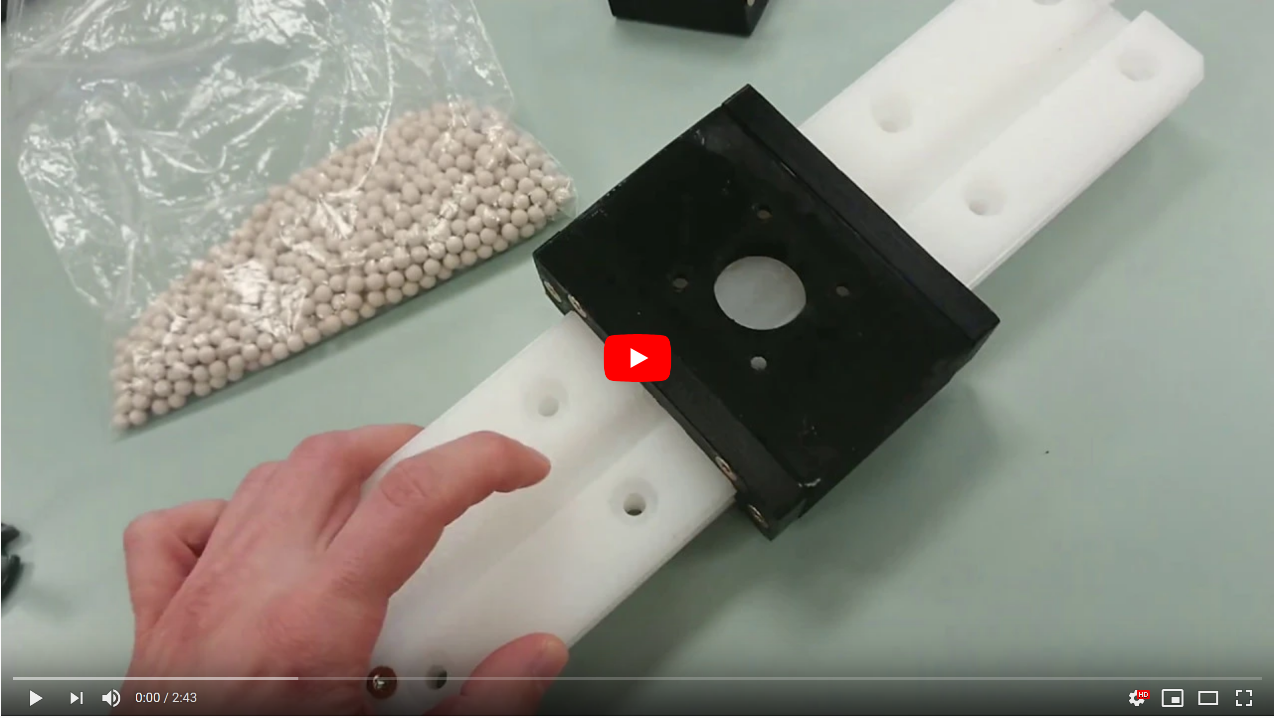
### First test H-axis machined and assembled
After finishing the axis generator I saved out a 600mm long test version, for 70mm and 50mm long M5 screws I had available. I milled out the parts from Formica Compacts using Bark Beetle, my homebrewed CAM software. The general first impression of the design direction is very positive.
__Fabrication stats:__
- Active machining time for all milled parts: 1hour and 15min _(about 2,5 hours total work with CAM, hold down, tool change and cleanup)_
- Print time one for one pinion and one block for fine tuning pinion position: 45 minutes
- Edgebreaking and cleaning/oiling: About 30min
- Assembly time (when new to assembling the axis type): About 2 hours
__Wins:__
- Very fast and easy to fabricate and assemble
- Easy to tune thanks to tune screws for v-wheels and motor
__Things to improve:__
- Try to reduce waviness in v-rail after assembly. Could have been caused by small head on machine screw, micro ridge from chipped end mill or general compression from tightening screws
- Movement range of stepper motor. Pinion cannot come completely free of rack now.
- Tune screws should be M3, not M5
- Edge of pinion can crash into fixed v-wheel holding part
- Design pinion to have a known position on motor shaft and reduce length
- Make pinion have a combo of without flat and with flat for motor stem _(so the pinion can be positioned far enough down the motor shaft)_
- Check why the vertical screws protrude a bit and fix
__Things to add:__
- Registration pockets and tabs in mating surfaces
- Holder for inductive homing sensor and trigger screw location
- Covers with felt wipers
- Hole/mount for zip-ties making strain relief for cables
__Things to do better next time fabricating an h-axis:__
- Wear gloves
- Make sure end mill is not chipped
- Make a smaller chamfer on the exposed of the rack teeth

_First version ready for testing_

_The parts were milled on a seven year old shopbot alpha. Note how the wooden washers allow for the parts to be nested with 0.5mm+"end mill diameter" clearance _

_Formica compact has sharp edges. Work gloves are reccomended_

_Store bought parts to the left, self fabricated parts to the right_

_Edge breaking with 180 grit sandpaper_

_I cleaned all parts end wetted all milled surfaces with WD40. For the rail and rack I used a WD40 type with PTFE lube_

_Mating surfaces, rack, and rails. It very satisfying how clean phenolic composites machine_

_The only sideways hole in the design is for the two v-wheel position tune screws. It needs to be drilled and tapped by hand._

_Tapping the 3D printed pinion for M5 set screws. WD40 on the tap allow you to tap faster and cleaner_

_The manually tapped holes with their screws_

_The fixed and adjustable v-wheel holding parts and the carriage plate_

_Carriage with openbuilds v-wheels and 3D printed helical pinion_

_This was the easiest orientation to start assembling the axis. Note the stripes from my end milled that was chipped. I was a bit sloppy sanding it away, and the protruding micro ridge might have lead to a wave shape in the rail._

_The 50mm long M5 screws was a fast and easy to get into the milled threads_

_The same with the 70mm long M5 screws_

_All screws tightened. I was careful to tighten all screws first a bit, then a more, then finally as tight as I could with a handheld screwdriver._

_Axis assembled_

_Detail showing the opposing rails_

_The tuning range of the v-wheels is enough to allow the carriage to be mounted from top, easing future maintanence_

_Voila_

_Note the tune screws for motor position and v-wheel position. The M5 size was a bit coarse, I will try M3 on the next iteration. The will easy precision tuning and signify that these screws are not for force, only positioning._

_Early wear with dust buildup. Testing wil reaveal if this only initail ear or a real problem. The openbuilds v-wheels are very coarsely turned, and might act like little saws in the beginning._
### Thread milling component in Bark Beetle CAM optimized
I made a small improvement to the thread milling component for Bark Beetle by making a hole size filter. This made it suer fast to set up the thread milling of the 35 theaded holes int eh 600mm long test axes. Imagine how much time it will save in milling the total of 18m of axes in the final machine.

_Very handy to be able to set a filter for which holes should be thread milled_
### Early start mapping out electronics needs
Lots of inputs and outputs needed. I added a star to non-critical features, so that the first spiral of my custom breakout board will be faster. I am currenlty aiming to use a Duet2 WiFi board.


[Back to index](#index)
<a name="week6">
***
</a>
# _Log:_ Week 6, April 1st
### Testing axis with dial indicator and second motor
notes testing:
__Zero load:__
- backlash zero load: 0.018mm
- deviation in positioning under zero load: 0.035mm
- total deviation zero load: 0.053mm
- repeatability: 0.005mm (not counting backlash, with backlash zero load assume 0.025mm)
__10kg load from top:__
- backlash under 10kg load: 0.022mm
- deviation in positioning under 10kg load: 0.035mm
- total deviation 10kg load: 0.057mm
- repeatability not accounting for backlash (direction dependent repeatability: +-0.002mm
side load:
- maxspring back deviation depending on sideways 5g load:0,043mm total, in either direction -0.021 and +0.022
- positional deviation with 5kg load in either direction: 0,28mm total, 0,14mm in either direction
__Dual pinion zero load:__
- backlash zero load: 0.011mm
- deviation in positioning under zero load: 0.05mm
- total deviation zero load: 0.0611mm
- positional deviation with 5kg load in either direction: total 0.14, -0.04 + 0.1
test - apply 0.05mm preload (mute step for one steeper):
- positional deviation with 5kg load in either direction: total 0.083, -0.038 +0.045
- backlash at zero load still 0.011mm
- deviation in positioning: 0,058mm
test - apply 0.1mm preload (mute step for one steeper):
- backlash at zero load 0.011mm
- deviation in positioning: 0,058mm
- positional deviation with 5kg load in either direction: total 0.088, -0.042 -0.046
__Initial conclusion:__
- Dual pinion reduces backlash with 50% and along axis deviation at a 5kg load with 50%.
- Preloading the steppers with 0.05mm makes no difference in backlash, but improves along axis deviation at a 5kg load with 40% more.
- This makes the stiffness difference of single pinion drive vs dual pinion with preload 0.28mm VS 0.083mm, quite a lot stiffer. About 3.37 times stiffer, which is significant for milling performance


[Back to index](#index)
<a name="week7">
***
</a>
# _Log:_ Week 7, April 8th
### Designing and printing pulley holders for more precise load testing

### Calculating material use and cost for the big test machine


[Back to index](#index)
<a name="week8">
***
</a>
# _Log:_ Week8, April 15th
### Jig prep extruder milling

_I have plan for registering the barrel in a shopbot in order to mill flats before i drill holes for heater and thermistor cartridges_
### Fixed broken generator from migrating to Freecad 19
The latest version of the freecad gears workbench had a change in the name of somme of the vlaues than be referenced. This was a relatively easy fix. Now the axis generator works well in the latest stable of version freecad together with the latest version of Freecad gears.
### Prepping a plan B - linear rail version of h-axis

_ I preparing a backup plan with tradition linear rails in cas testing shows that metal v-wheels running on milled phenolic resin composite rails is durable enough_
### First spiral of hopper adapter for continuous fiber auger extruder

_for the pellet extruder that i will use for continuous fiber extrusion i need a simple hopper to get started. I am planning to use a transparent jucue bottle as a container. I designed this 3D printed adapter to make the transition between the barrel and the bottle._

_Detail showing the thread made with the subtractive helix feature in the Feeacad PartDesign workbench_

_Before finalizing the dsign i printed a test threads. It two takes to get it right_

_I came up with a nice trick to make print friendly threads. Most threads have a 30degree profile angle, which becomes to steep of an overhang for most printers. But only one side of the thread is engaged during tightening, the other side can be at a print friendly 46 degrees._
### Evaluating simple nozzle hack for continuous fiber extrusion

_In preparation for making a nozzle for continuous fiber extrusion, I made a quick check to see if would be feasible to simply drill a hole in the store bought nozzle from Robotdigg. It looks reasonable, but I am worried about melted plastic creeping out through the fiber feed hole._
### Formica compact for big machine ordered
I have ordered 18m2 of the 12mm Formica comapact. Leadtime is 6 weeks because of pandemic logistics. Hopefully it will be faster.
[Back to index](#index)
<a name="week9">
***
</a>
# _Log:_ Week9, April 22nd
### Machining holes for thermistor and heater cartridges in extruder barrel and nozzle

_This is the current design of the Pellatis extruder that I am developing in collaboration with Torbjørn Ludvigsen. It has three thermistor cartridges for three heating zones and two catridge heaters in the nozzle. The other two zones have band heaters._

_I realized I could make a simpler jig for making the catridge holes if I used some 19mm thick MDF leftovers_

_Milling the halfpipe jig. Note the slot in the middle, this improves stability in case the diameter is slightly off (most likely it will be). Because the machine makes its own jig, the part is automatically registered. No need to dial in the jig location._

_Barrel clamped down with a modified mount for plumbing pipes._

_Using the trochoidal milling feature in my Bark Beetle CAM. A shopbot is not meant to cut steel, so the lower load from highspeed machining makes this possible._

_Plunge roughing the flats on the nozzle._

_All the flats done and drilling locations spotted. Drilling speed with min 6000RPM spindle on a gantry is very tricky, so I planned for the jig to travel to the drill press in the wood workshop at Fellesverkstedet._

_The jig and barrel transfered to the drill press. Like this I didn't have to worry about drilling at the correct angle, because the barrel remained rotation locked in the jig during transfer._

_All the holes done, counter sunk and lightly sanded. Corresponding cartridges bellow_
### Printing the hopper adapter

_The hopper adapter requires support. I uses support on the bed only to simplify cleanup._

_The printed hopper adapter screwed onto a cut juice bottle. The transparent sides should make it easy to spot when plastic pellets/shreds should be refilled._
[Back to index](#index)
<a name="week10">
***
</a>
# _Log:_ Week10, April 29th
### Preparing for casting a custom nozzle or ordering metal 3D print online

_In preparation for making a custom continuous fiber nozzle for the extruder barrel, I wanted to make sure that I had reverse engineered the correct thread pitch and diameter. Again I used the same 30 deg + 46deg profile angle trick to make print freindly threads. I was lucky that optimal print orientation and tightening force direction matched up for this._
### New idea for continuous fiber feeding and embedding

_I came up with a new idea for the continuous fiber feeding. I have been quite concerned about the hole for feeding fiber into the nozzle becoming clogged with plastic. During last class the converstion between Cederic and Neil on the mark forged machines having two nozzles, one of them for depositing the fiber "dry", inspired me to rethink. In my reseach I have seen that Ingersoll and Thermood use a dragged roller  to flatten their print beads for less voids and better layer adhesion. I am considering sending the fiber in from the side, extrude over the dry fiber, and then smoosh it together with a roller on the other side. This would have to be sitting on a 4th axis rig with continuous rotation. This allows me to keep a standard nozzle on the extruder I am developing. It will also make it easier to experiment with conductive and other types of fibers. Next up simple manual testing and rough CAD design._
[Back to index](#index)
<a name="week11">
***
</a>
# _Log:_ Week11, May 6th
### Hacking heat sinks for the extruder barrel

_The heat sinks are made for cooling brushless RC motors and need some modifications so that two of them can be mounted opposing each other._

_I bent the outer ribs to a 90 deg angle with a steel plate and a hammer. This gives me opposing surfaces for mounting the pair._

_The arcs of the heat sinks were more than 180 degrees and needed chopping._

_Drilling holes for mounting_

_The heatsink pair test mounted on the barrel. They have an important task; prevent the temperature of the upper part of the barrel from being so high that the pellets deform (and clog) before they reach the auger._
### Milling insulated gaskets

_The hopper adapter is printed from PLA and extra vulnerable to heat deformation, so I decided to extra conservative and make an insulating gasket from 0.7mm thick Formica. _
### Assembling the pellet extruder
I am developing the Pellatis pellet extruder together with Torbjørn Ludvigsen. The files are hosted in this [repo](https://gitlab.com/tobben/pellatis). I am planning to make a continuous fiber addon to this extruder, with the aim of making high performance biodegradable composites on a large scale.

_Store-bought parts to the left, modified store-bought parts in the center and self made parts to the right._

_Inserting the heater cartridges into the nozzle. Having a pair in the nozzle helps ensure and even flow of plastic, and by having a thermistor in the nozzle we avoid over heating the plastic in the metering zone._

_The insulating gasket goes between the barell and hopper adapter_

_Screwing the nozzle onto the barrel with reasonable force_

_The Pellatis extruder assembled. Next up electronics wiring and PID tuning._
### New idea for a simple DIY mini mill

_I got a new idea for a fab academy at home type machine. I want to use Jake style flexures for both the stepper/pinion and bearings. It will have v-rails the the h-axes, but regular 16mm OD bearings at 45deg instead of v-wheels. The architerue is the same classic VMCs, so that I can use three steppers instead of four. More sketches coming soon._
[Back to index](#index)
<a name="week12">
***
</a>
# _Log:_ Week12, May 13th
### A simpler flexure based h-axis
__File:__
- https://gitlab.cba.mit.edu/classes/865.21/site/-/blob/master/people/jensdyvik/h-axis-16mm-od-bearings.FCStd

___

___

___

___

___

___

___

___

___

___

___

___

___

___

___

___

___

___

___
__Notes:__
- Makes hole 2.7mm?
- Include washers at overhangs with chamfers, or skip?
- Increase flex space for bearing flexure to 2mm
- Add chamfers to ease start of self tapping /screwing
- Most nema 17 motor shafts might be too long, check
- Needed washers as spacers for the motor to avoid pinion crashing into
- Feet became too short
__To do:__
- Update carriage body to have hole dimensions driven from spreadsheet
- Make more robust constraints in freecad that wont flip with large dimensional changes
- Clean up spreadsheet in freecad file: remove unused variables
- Make FDM only version
- Make project repo for axes
- Research best filament and proportions for flexure, reduce creep
### A more robust h-axis based on linear rails
__File:__
- https://gitlab.cba.mit.edu/classes/865.21/site/-/blob/master/people/jensdyvik/h-axis-linear-rail-test-version.FCStd

__

__

__

__

__

__

__

__

__

__

__
__Notes:__
- make m6 bolt non treaded holes a little larger
- make with m5 holes?
- pinion still cant clear the rack
- make dowel pin holes 1 mm shallower?
- increase spacing between blocks. Too tight, lucky. What went wrong?
### Preparing for final presentations
__Questions:__
- Is it possible to build a large format cartesian research machine with reasonable precision using fab inventory tools and large degree of self fabricated parts?
- Can a linear actuator made with machined phenolic resin composite sheets have sufficient performance and longevity for this task?
- Is it feasible for a machine building enthusiast to do large format continuous fiber 3D printing with biodegradable resins and fiber (PLA+Hemp)?
- What is the simples way to build you or own pellet extruder suitable for printing 1-2kg of filament an hour with a 2-3mm diameter nozzle?
- What is the most suitable mechanism for in situ embedding of continuous fiber in a pellet extruder output?
__Demo__:
I plan to demo each of the three axis types I have developed and hopefully also demo the pellet extruder making PLA spaghetti.

_First h-axis with v-wheels in the center, to the left a simplfied axis for learning with 16mm OD bearings at 45 degrees and to the right a proper axis with classic linear rails and more contact surface for helical rack and pinion._

[Back to index](#index)
***
### _Change log_
- 23rd of February 2021 - Page started
- 4th of March 2021 - Added component, system and tweaked bio. Moved link images to repo
- 11th of March - Added week3 log update
- 17thof march - added wwek4
- 25th of march - added wwek5
- 26th of march - added more pics
- April - stopped updating changelog
---