How to Make Something that Makes (almost) Anything | S21 | Component
DIY 3D scanner for CNC machinesPhotogrammetry and line laser scanning
Question:
Can scanned data from DIY device accurate enough to be used as reference data for other machining process?
How does photogrammetry results compare to line laser scanning?
Scanning + CNC Precedents:
Automatic part localization in a CNC machine coordinate system by means of 3D scans
3D Scanning System of Structured Light for Aiding Workpiece Position of CNC Machine Tool
On-machine 3D measurement of workpiece dimensions based on binocular vision
A helpful intro to the mathematics of photogrammetry
Evaluation:
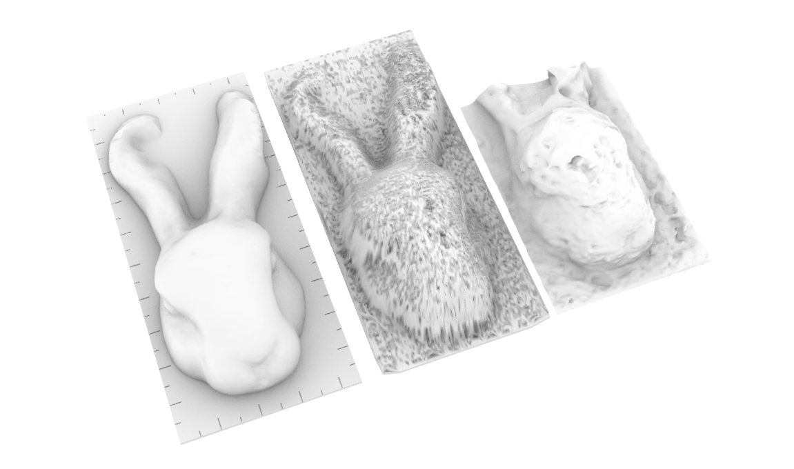
Results
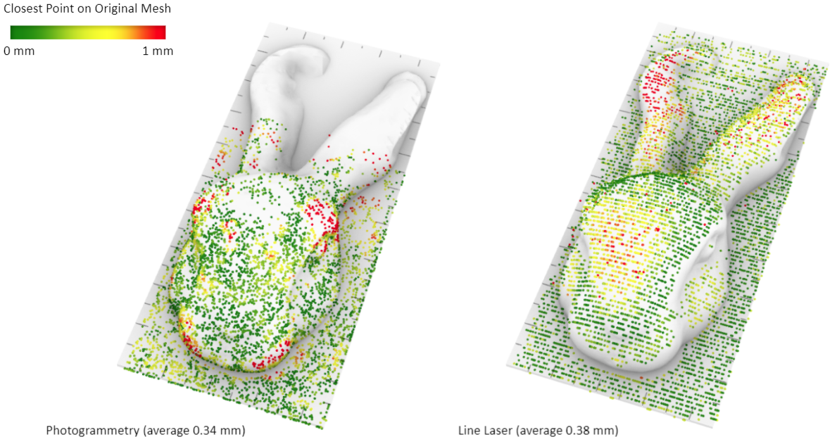
3mm average distance / 1mm average distance
| Photogrammetry |
Line Laser Scanning |
|
|---|---|---|
| Bunny results |
Average 0.34mm Error(>1mm) exist on braod range |
Average 0.38mm Error(>1mm) points clustered |
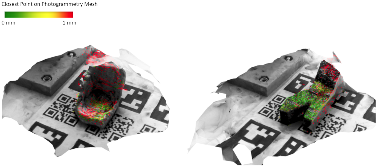
| AL results | generated geometry well | poor results on tilted none smooth surface |
| Pros | Better detail / captures overhangs |
Acoomplished without specialized software(with Grasshopper or JavaScript) |
| Cons | Export photos to software such as meshroom Need markers/textures Hard to capture surface with high reflection |
generated all geometry captured in photos Hard to capture surface with high reflection |
Future work:
- Develop stremlined workflow
- Improve image processing for better accuracy on line laser scanning
WEEKLY UPDATES
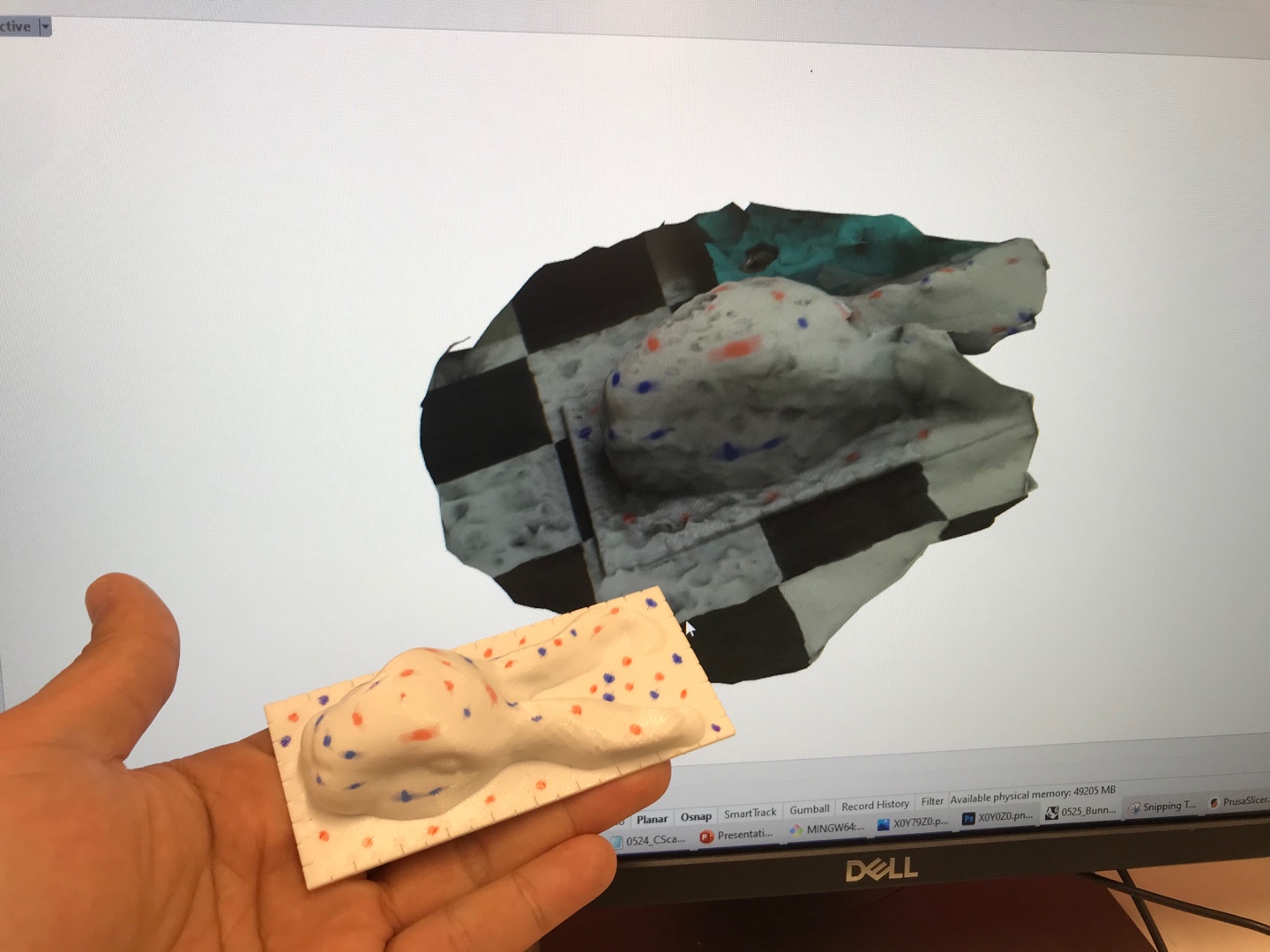
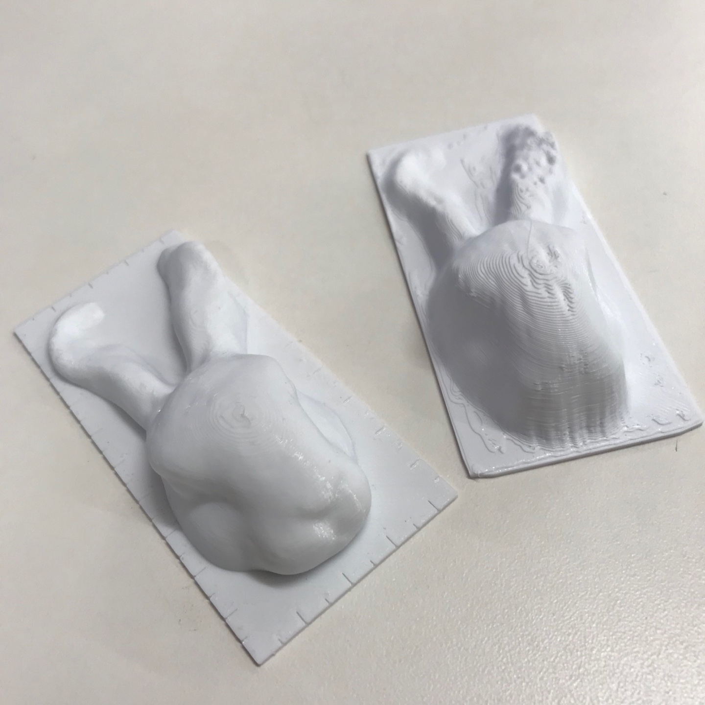
5 / 21 / 2021 - Bunny Test
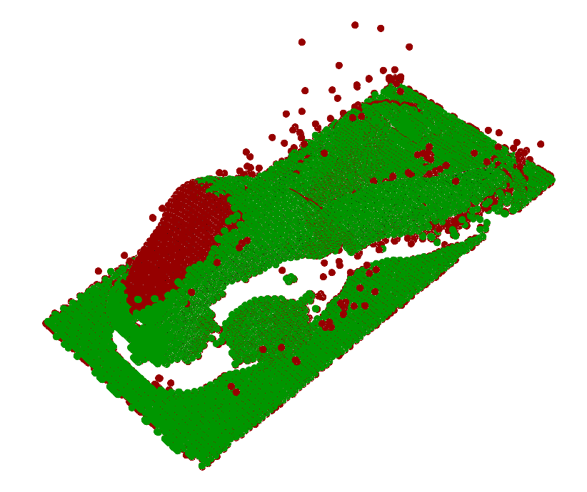
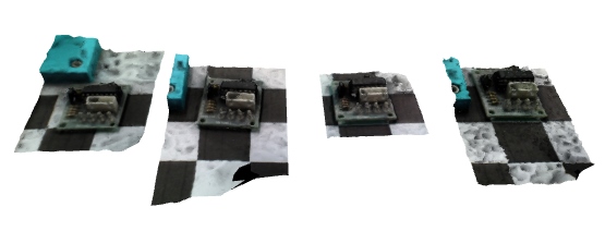
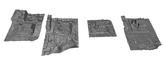
5 / 19 / 2021 - Aluminum casted part scan Test
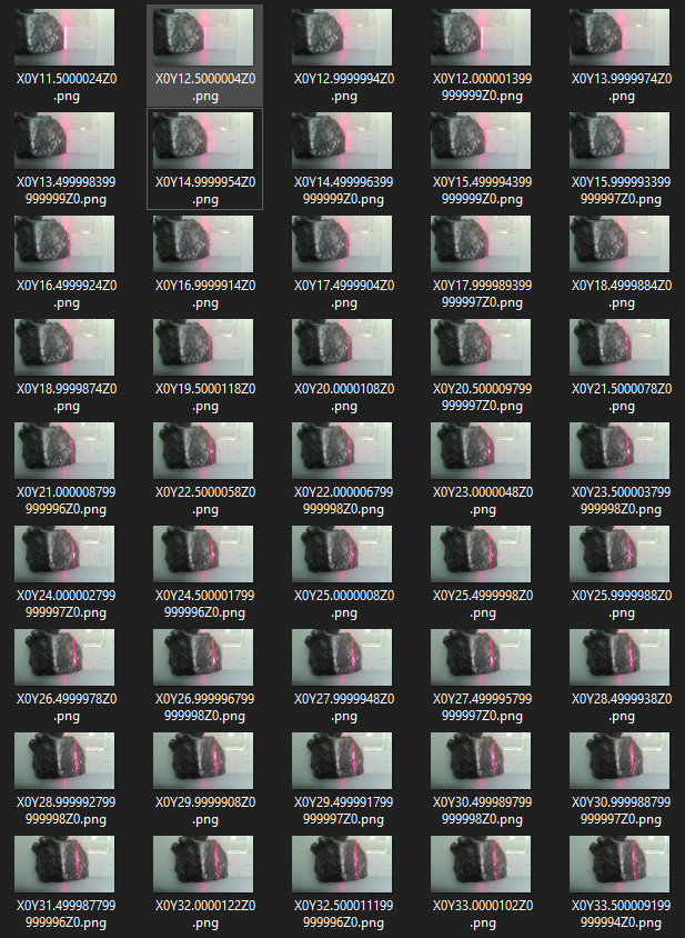
~70 photos taken from every 0.5mm Y steps
Use gcode to move each steps
Single photo taken from 66 steps
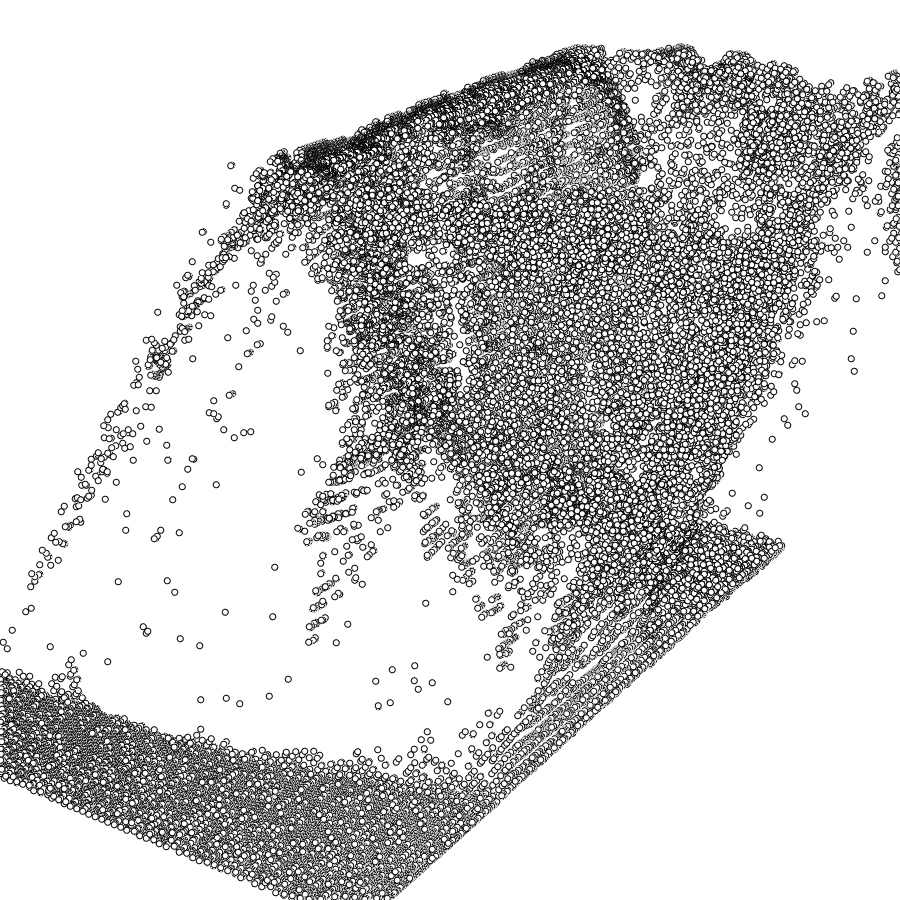
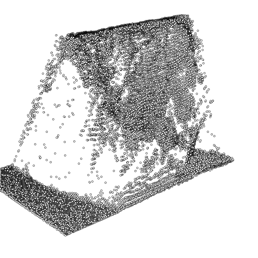
Point cloud results, left a lot of noise due to poor image procecssing results
Point cloud results, manually removed some noise, right
Conversation with Nathan & Jake
- Simple camera rotation module that can be used for photogrammetry.
- Comparison between laser scan result and photogrammetry?<
- Photogrammetry(Nathan's page)
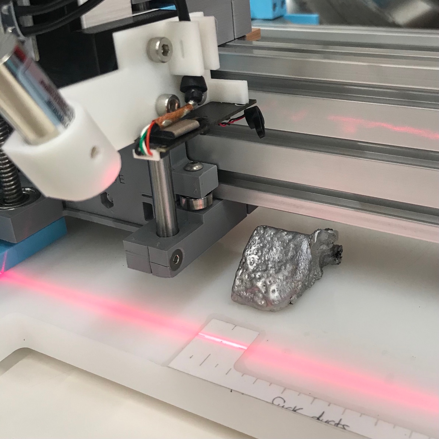
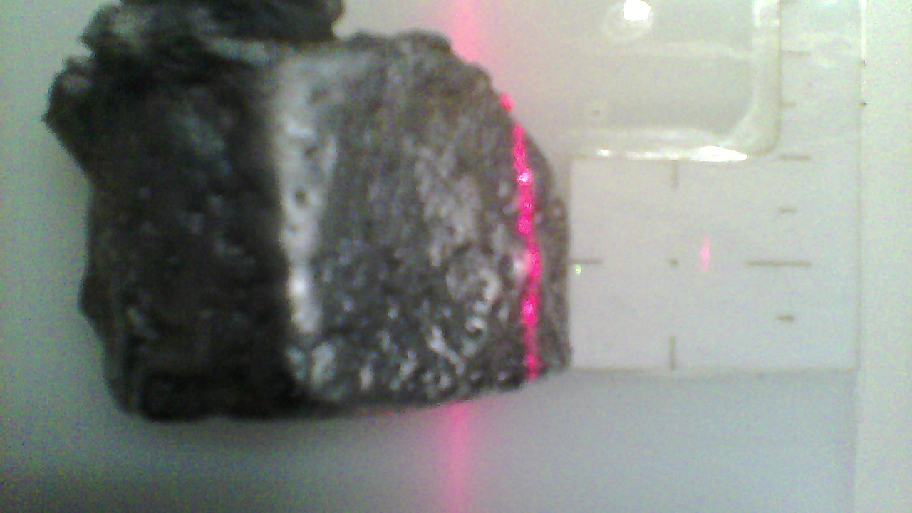
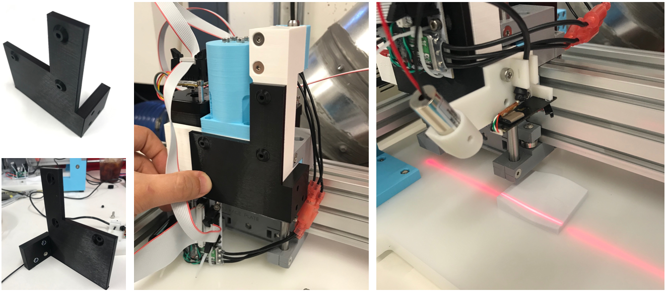
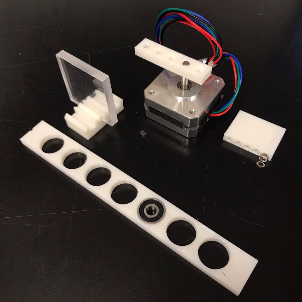
5 / 18 / 2021 Line Laser First Test
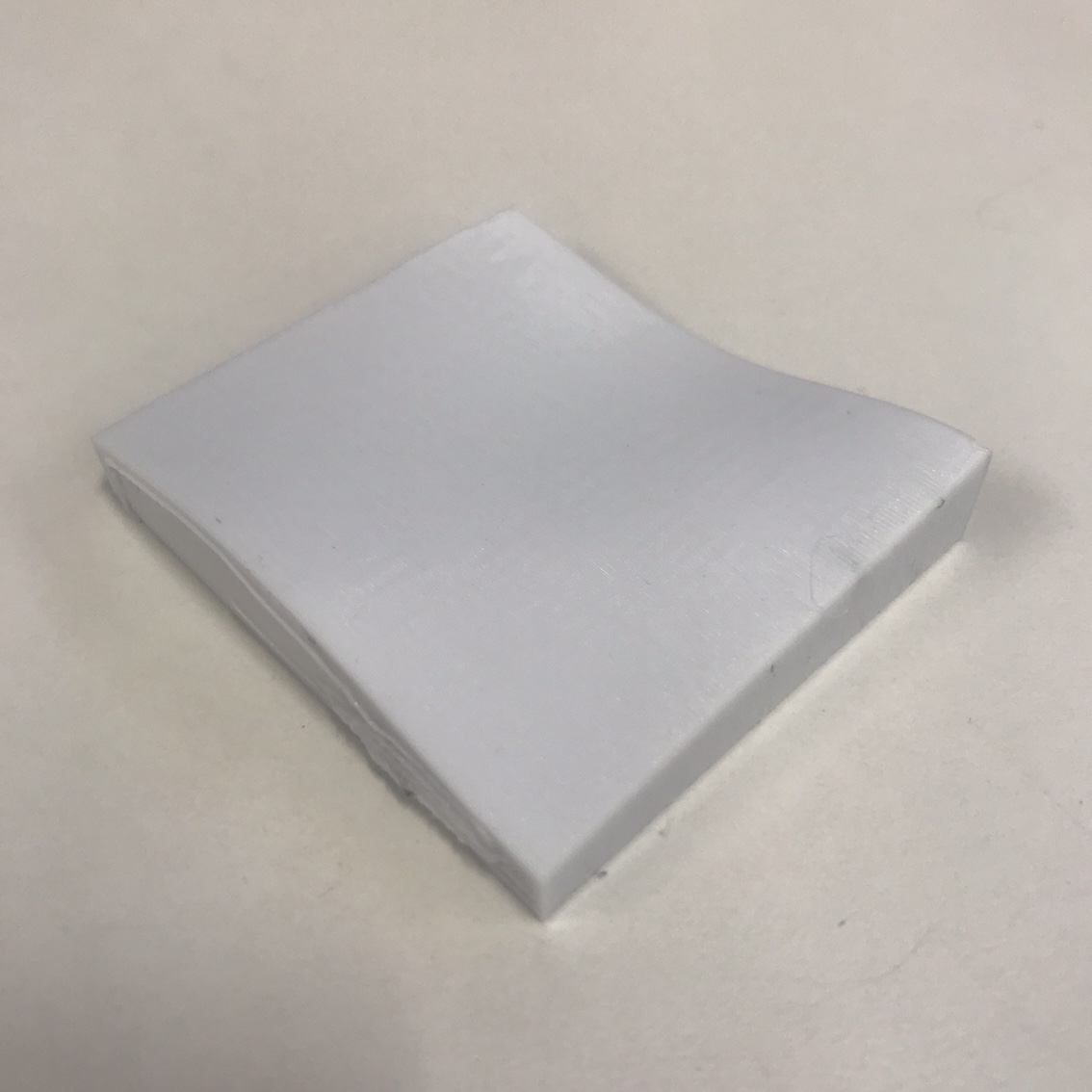
Test piece
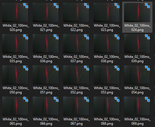
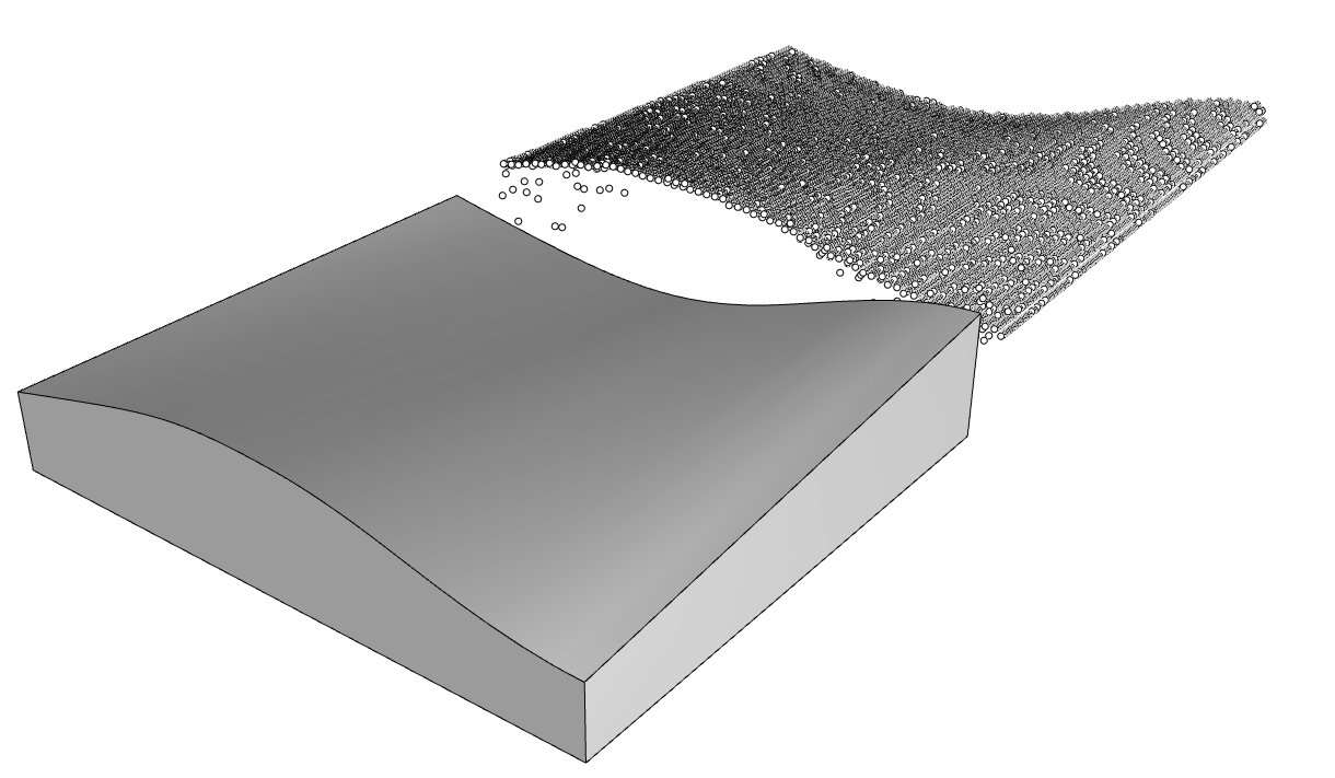
Image taken from every 1mm
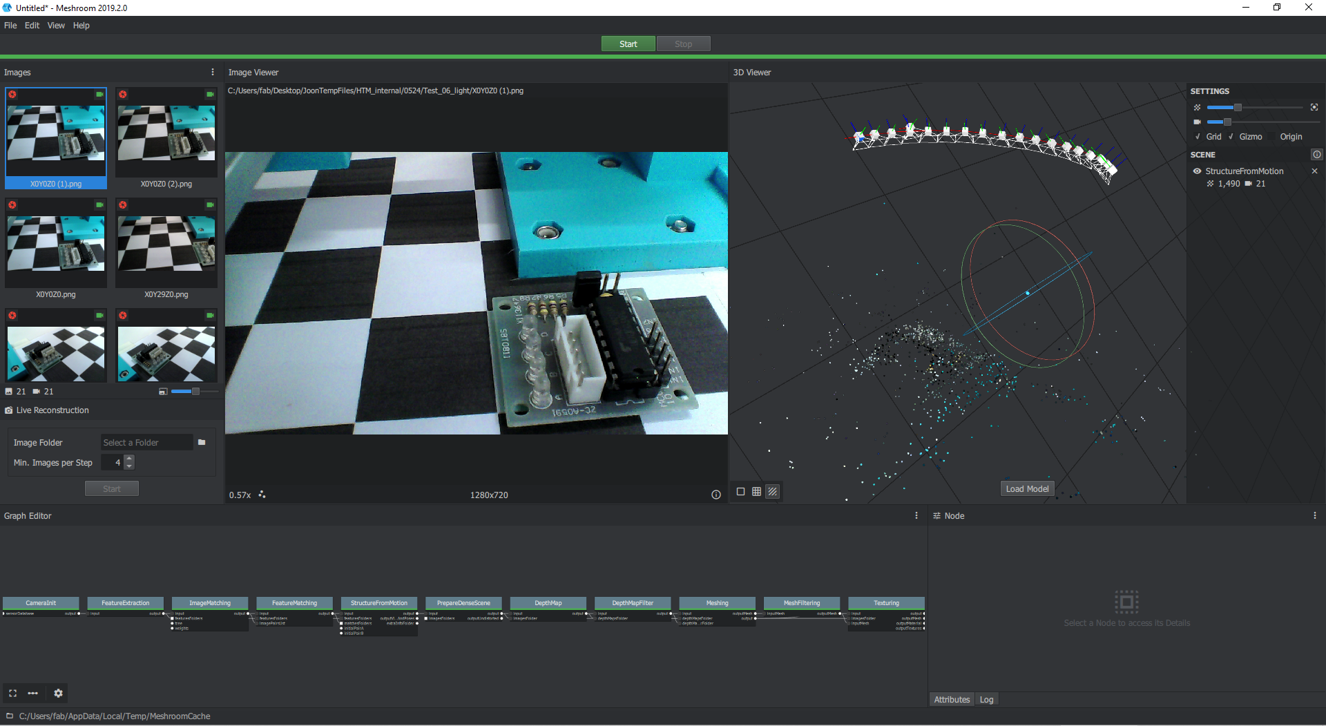
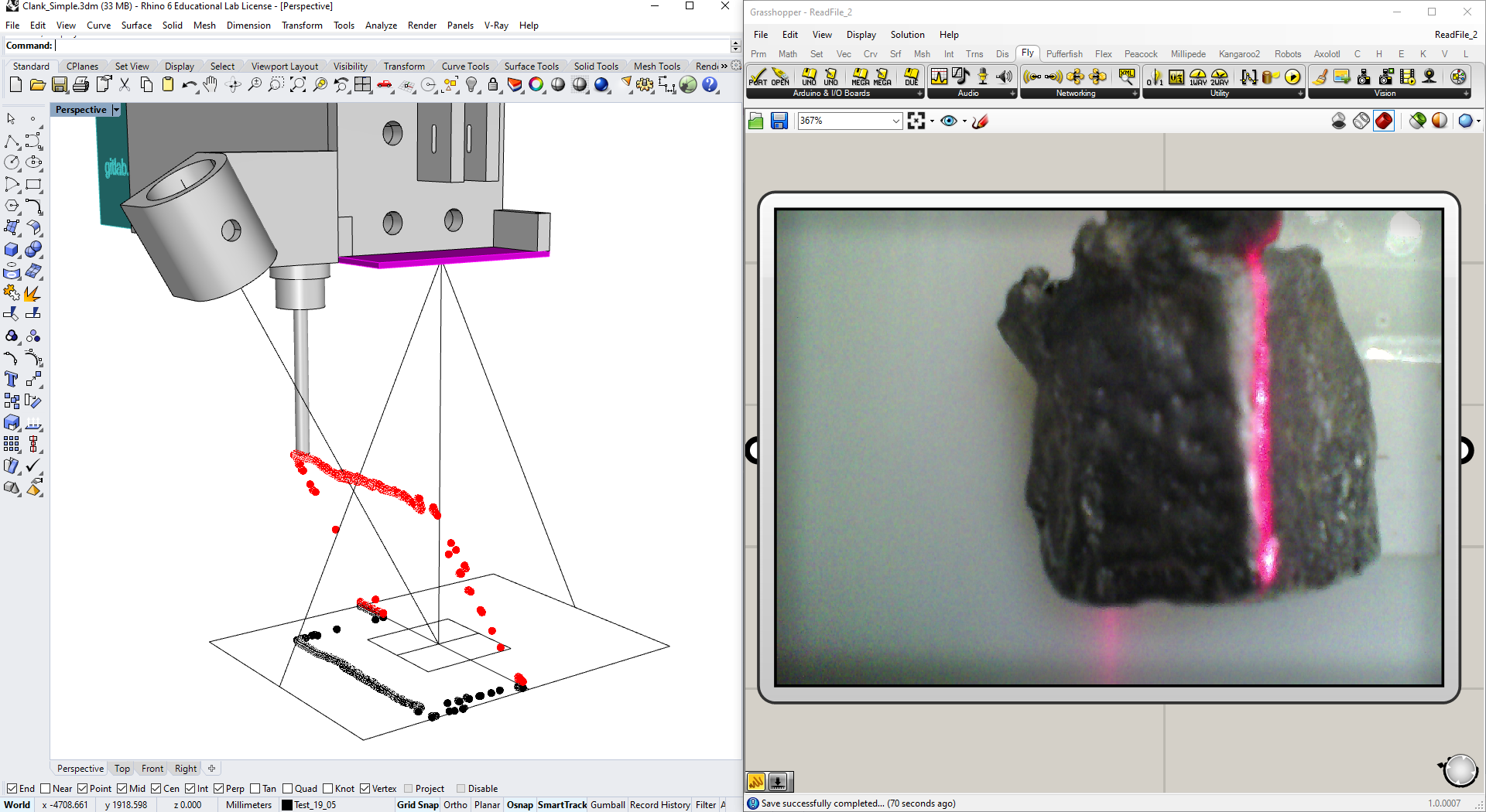
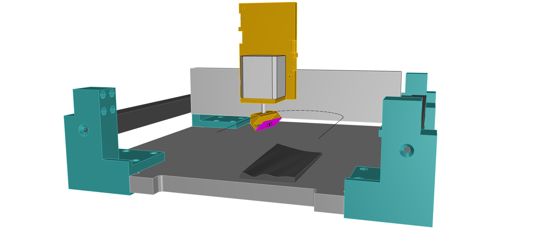
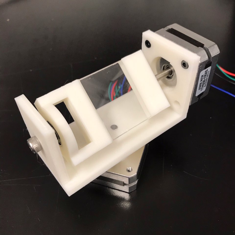
5 / 16 / 2021 WebCam + Grasshopper + Clank
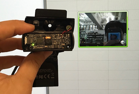
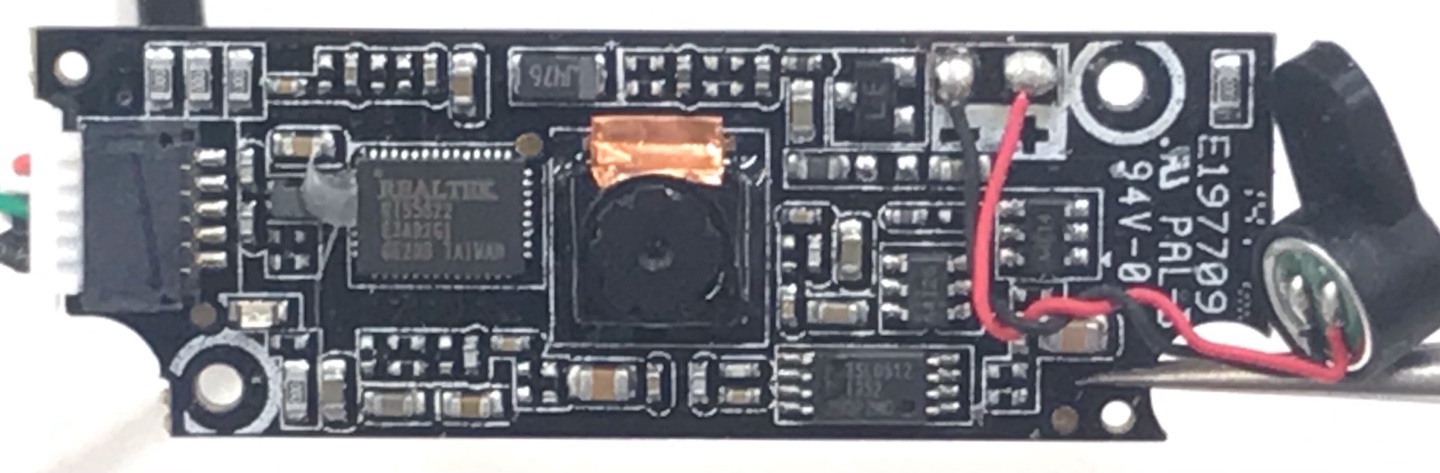
Attached on Clank:
vvv
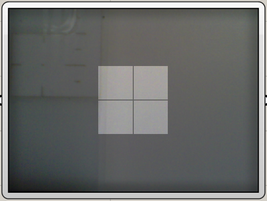
Calibration:
vvv
4 / 28 / 2021 Update - Line laser scanning
This week, I tested a line laser to read geometrical data of a scanned object. To try line laser scanning that I studied last week, I need a camera that reads reflected lights on the object's surface and interfaces that process captured image. Using ESP32 Cam was one of the great options, and a video that Prof Neil Gershenfeld shared in Htmaa class was a great example of processing images. However, I was not able to use Harvard University Wifi to link my local server and ESP 32 camera. Working with my cellular data tethering worked well, though. So I tried to find something else and found the Firefly plug-in for Grasshopper.
Firefly is made by Andy Payne, who took HTMAA a while ago. The plug-in lets users access Arduino Uno or microcontroller easily, and the latest update he made was adding computer vision components in the plug-in. Using his plug-in, I easily link my webcam. The video above shows a quick test of processing images from a webcam, reading the Z location of the red light.
Notes:
- Reading Video Input
ESP32 CAM | OV-2640, Max resolution 1600 by 1200, not working with Harvard University Wifi
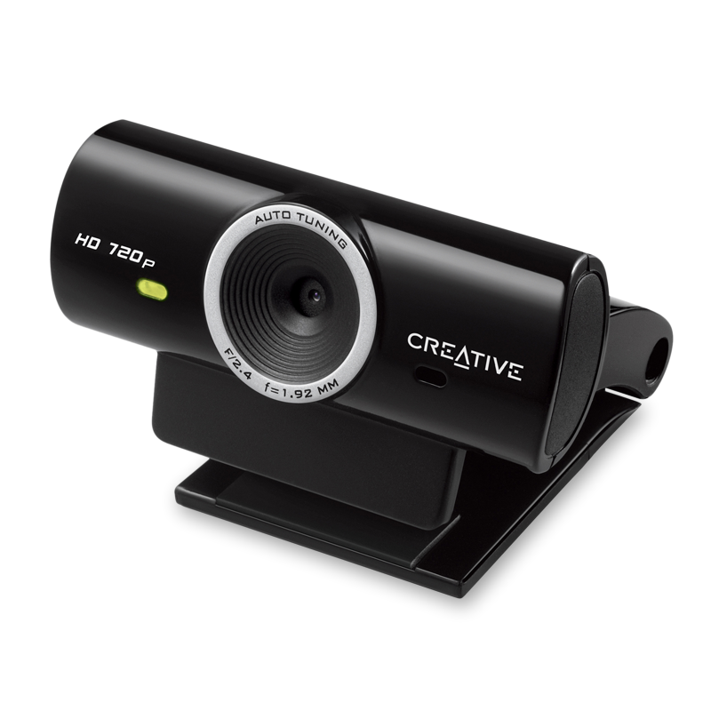
WebCam | Creative, F/2.4, f1.92mmm, auto tuning, HD 720p
Grasshopper Firefly | max reading 640x480 resolution, max frame speed 25ms - Reference links for study - Image processing reading lines
Extracting red laser line from image - take read channel and search for the highest intensity in a row
Obstacle detection using Laser and image processing on LOGI-Bone
- Problems to solve and TODO
Noise points on red lines
Some surface materials(such as matt black) does not reflects red lights Mesured distance check needed
4 / 20 / 2021 Update - Research on line laser scanning
The test performed with the cheap time of flight sensor(vl53l0x) yielded poor results in capturing accurate distance in a close distance range between 10mm to 500mm. Moreover, scanning takes a long time at 60ms per each single capturing point. As such, capturing an area of 50mm by 50mm marked by a 1mm grid will take 150 seconds (50 * 50 * 0.06).Besides, while reading through previous HTM 2018’s scanning review pages, I found that line laser scanning techniques may be a promising method for inspecting molds and aluminum casting parts for formal and material integrity. I am interested in scanning a casting mold and its casted aluminum pieces. The mold is several inches in depth and carved from sand and regolith, while the casted aluminum pieces have a rough surface texture. a In manufacturing industries, line laser scanning techniques measure width, height, depth, gaps, and angle of the product for inspection, which are exactly needed for my scanning process to verify formal integrity.
Line laser scanning techniques operate by computing images of laser lines projected on objects. Working with a rotating platform, a robot arm, and a linear axis, the scanner(camera on scanner) captures reflected laser images from multiple locations. Software in tandem with the scanner extracts pixel location of reflected laserlight by modifying brightness, contrast of the image. Then the location of pixels are converted to geometrical information of the scanned object.
There are some good open source projects such as FabScan, and Smartphone app Moedls
- FabScan (FabLab in Aachen, Germany , 200 EURO)
- Moedls ( ios app, 2013)
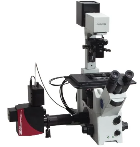
- scanCONTORL, Industrial 3D scanner for inspection (Micro-Epsilon)
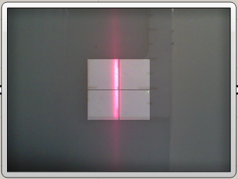
3 / 18 / 2021 - Laser and Lens
Both confocal and lidar-based scanning method use a rotating mirror to point lasers to diverse directions. This rough model using a pet laser toy, angle brackets, and heavy motors, so did not allow accuracy for now. But it was interesting to see moving lasers on the white wall.
The next step:
- Dissemble pet toy laser and get electronics and laser
- Try other types of light-weighted motors
- Test accuracy of the rotation angle on two axes
- Study methods to read laser point data using a pinhole
- virtual interface design to check mirror states and laser vector
3 / 11 / 2021 - Confocal? LIDAR? Laser? or others?
3D scanning of object - Confocal? LIDAR? Laser? or others?The scanner that I am interested in is a small device that can be attached to a CNC or machines for post-processing human or machine made objects without any reference 3D data. The attached scanner would make 3D geometry for post-processing like milling on top of hand-made clay objects or 3D printing on top of curved surfaces. The scanner would also be used for inspections during the process of milling or powder printing.
The scanning scale that I am interested in is between 0.1m and 1m. Before starting to make anything, I researched the potential options. There are many reference projects (maker's DIY projects) of 3D scanners using photogrammetry, laser scanning, and LiDAR within that scale. But there are unfortunately no DIY examples of Light stages or confocal microscopy, possibly because light stages add much more complexity to machines since they would need rotational axes with lights. My interest is in putting a small device on top of existing machines, so I decided to focus on the confocal microscope first.
Confocal
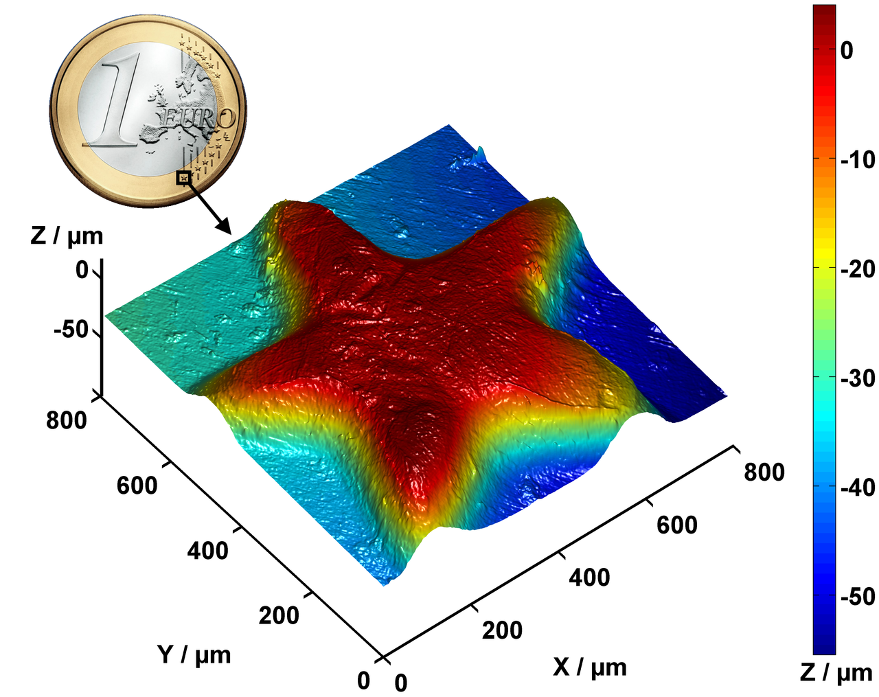
One big question that I had was whether reflection confocal microscopy would be suitable for the 3D scanning of relatively big objects. Confocal microscopy often produces high-resolution, layered images of tiny areas of 1mm by 1mm with a resolution of 1.0 nanometer, but that is not what I am interested in.
Confocal scanning uses laser light to capture the 3D geometry of an object. By rotating mirrors, laser light traverses XY locations on the sample. A detector with a pinhole only receives the reflected lights that come out from the focal point at a specified Z level.
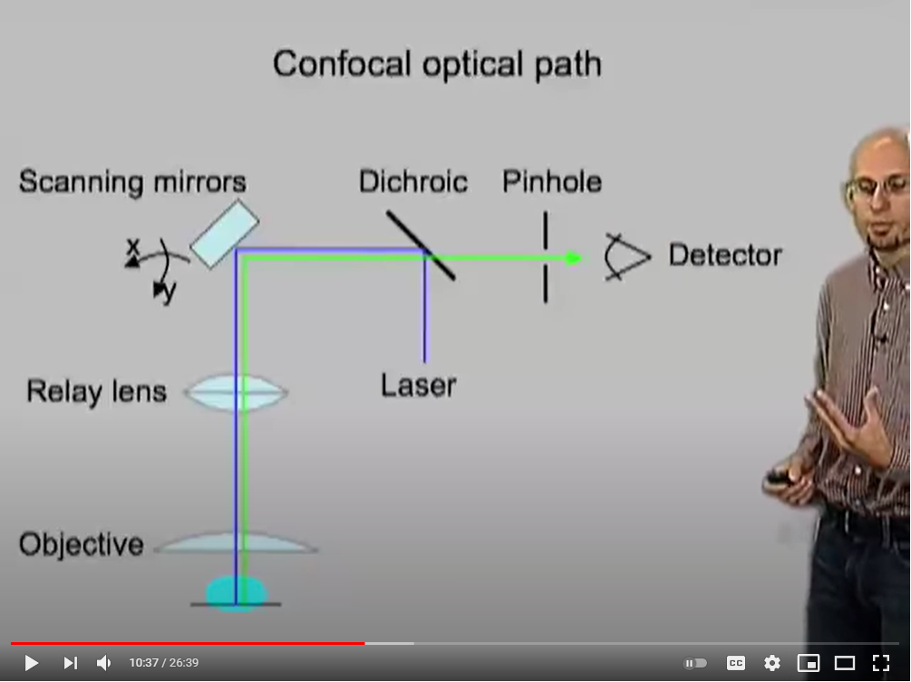
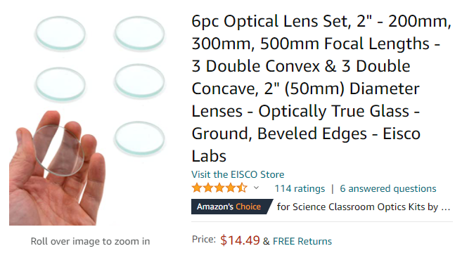
But even after watching instructional videos and documentation of confocal microscopy, I found the process difficult to understand. I tried to understand the scanning step by step by drawing the line traversed by the laser lights, using a diagram explained in this videoas a starting point. I also found a lens from Amazon and used its dimensions for test model.
Lens:
50mm diameter and 200mm focal length.
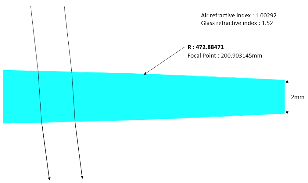
The next question was how to calculate the curvature of the lens. To do this calculation, I assumed that the two curved surfaces of the convex lens are arcs and that 2mm of thickness exists on the edge of the lens. For the refractive value of air and glass I used 1.00292 and 1.52. Then, I used Snell's law to compute the focal point. I found that radius 472.8mm makes the focal length approximately 200mm.
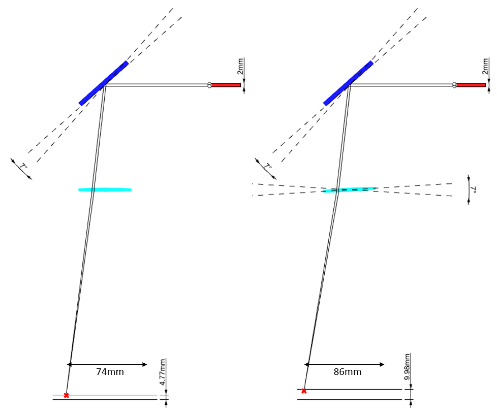
Using the lens geometry, I tested how the rotation of the mirror affects the X and Z locations of the focal point of the laser beam. The two lines starting from the red rectangle indicate the borderline of the laser light. As the mirror rotated 7 degrees, the X location of the focal point shifted 74mm. If I rotated the lens and mirror in opposite directions at the same time, the focus point of the light moved 86mm. The Z location of the focus point was located between 0 to 4.77 mm and 0 to 9.98mm. The range of movement for the focus point is larger than I thought but I am still not entirely sure what that means for my design without further study.
Components in confocal
- Detector Reading light using color sensor discribed in htmaa hello VEML6040?
- Pinhole What hole diameter it should be?
- Lens Optical lens set from amazon / 200mm - 500mm Focal Lengths / $14.49,
- Mirror
- Laser
Magnifying glass from ebay / $1.61
Laser cut acrylic(??)
There is an interesting youtube video about how to cut smmoth arcrylics sections from Thunder Laser. The instruction was not straightforward to follow, as the laser cutter the instructor is working with is different from what we have in Harvard Lab and some parameters he dealt with, like the Laser tube and blowing rate, were ones I have not used before, but I will check this method out for next week.
Desierable set-ups:
80W Laser tube, week blowing, Speed 6mm/s Power:50%
One tested cut used following set-up:
Speed 3mm/s Power: 70% from the machine side, and power 95 set-up in thunder program.
I made a two axis rotating mirror with simple 3d printed housings. However, considering that the mirror only needs a few degrees of movement, the stepper motor that I used is unnecessarily big and heavy. I will look for other stepper motors that can be used to rotate the mirror.
LIDAR
3D scanning using LIDAR could be more easily found
2 / 25 / 2021 - Project Idea
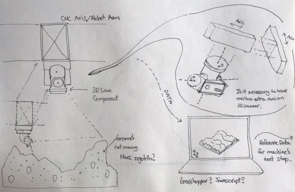
Project Idea
I am interested in developing a component that 3d scan objects and builds 3d data. The device would scan bojects that are heavy or cannot easily be rotated or tilted. The component could attach to a CNC or robot arm and scan the object. To go with the device, I want to make an interface that visualizes the captured object synchronically.
Some thoughts and questions:
- Does adding one or more rotating axis on the device to capture images from many directions increase 3D scan accuracy? Or is the accuracy of the model something that can be solved by software?
- What is processing the captured image or points? The device itself or a wirelessly connected computer?
- How long would this scanning process take? and how to imporove speed of scanning process?
- Is it a feasible project for me...? I can do programming, my background is not CS!