21.03.18 Electronic Production, Electronic Design, Embedded Programming
This week while waiting for some of the parts of the TinyZ to come in amongst others, I decided to see how well I could handle jumping to some more electronics work. The previous week, I had familarized myself with some aspects of the electronics production process by milling a quick test PCB on the Roland SRM-20.
Therefore, to try my hand at some more aspects of producing my own electronics, I tried to follow a similar assignment to which the students in HTMA had undergone in the previous semester - to make one of the Hello World board examples that Neil had designed, but add an LED and a push button.
First off, after using KiCad last week to design my PCB, I actually ended up switching to Eagle for this week. While I appreciate the ease of visualization in KiCad, I simply just found the user interface to be a little more friendly when using Eagle. Thank you to Zach and Anthony for making these quick tutorials which introduced me to how to use both platforms. For my board I decided to use the ATtiny1614 for my design, which is a 14 pin microcontroller that also comes with our at home fab kit.
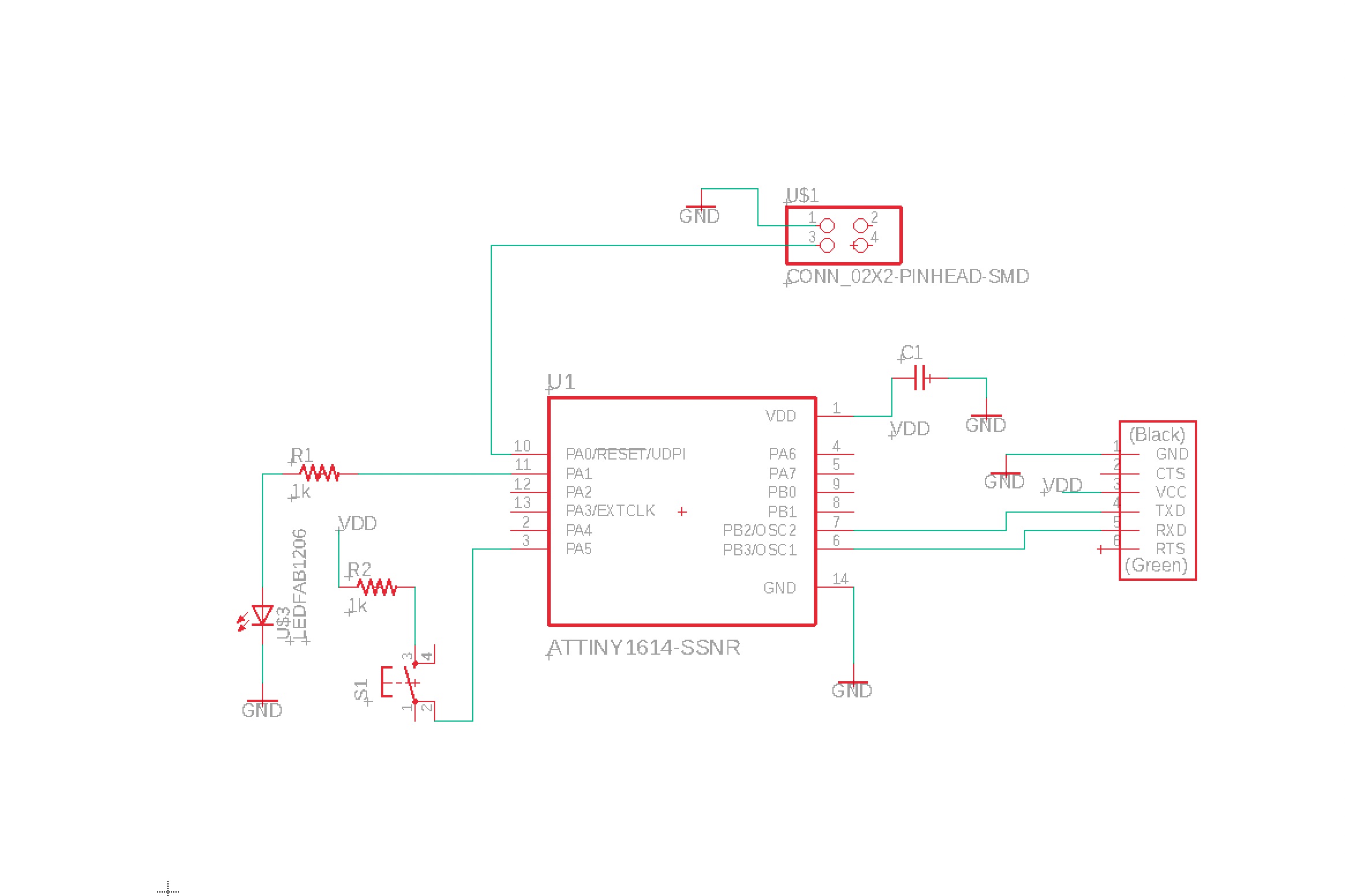
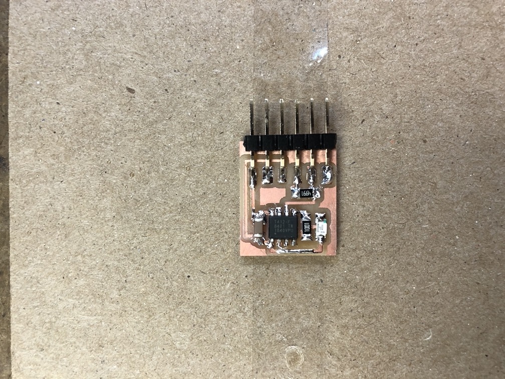
After completing the circuit diagram, i wired up the components of the pcb in a way that is consitent with the diagram. As I knew I would be a beginner to the soldering process, I actually tried to make my design fairly spread out to give myself plenty of room while accessing different points to solder.
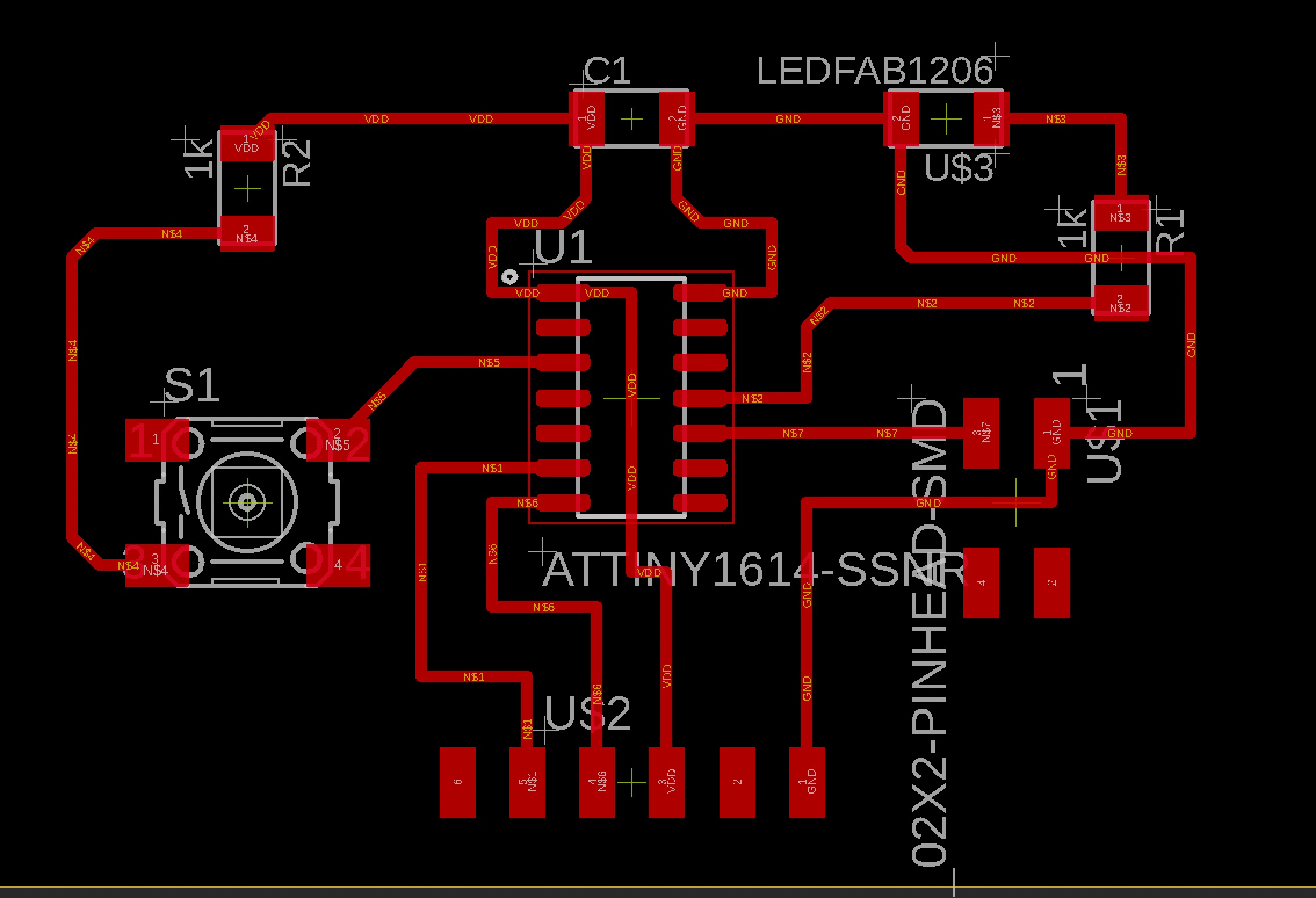
Here is my finished board design in .png format because I was planning to use a .png in mods to produce g-code for the mill (I also took note, to set my dpi settings to 2000 dpi in mods because I am currently exporting this on a retina display, Anthony mentioned this in his tutorial). Also included is the outline of my board to cut it out. I tried adding my name to the design of the board too for additional style points.
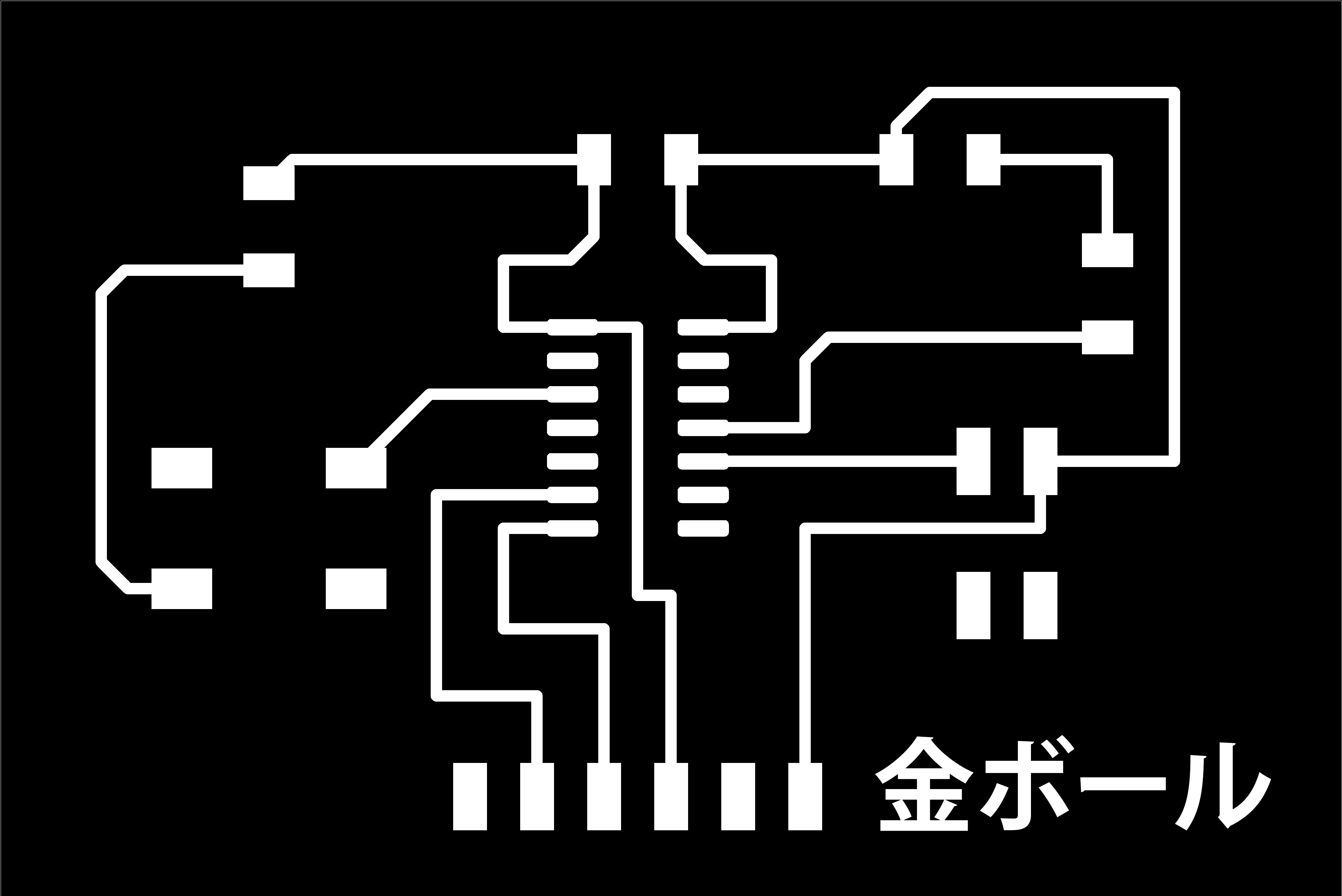

This time when using mods, I went with playing with some of the default settings instead of just pushing through the standard settings. Instead of “4” outlines around my design, I tried out “0” to mill out the entire fill, again for style points.
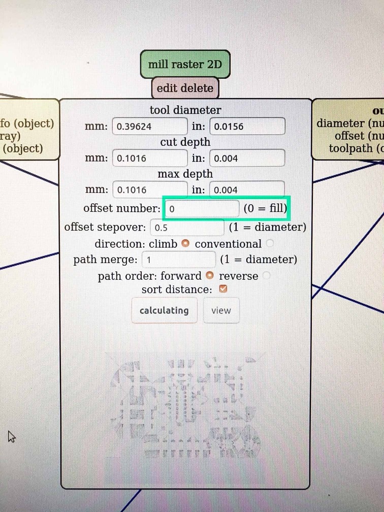
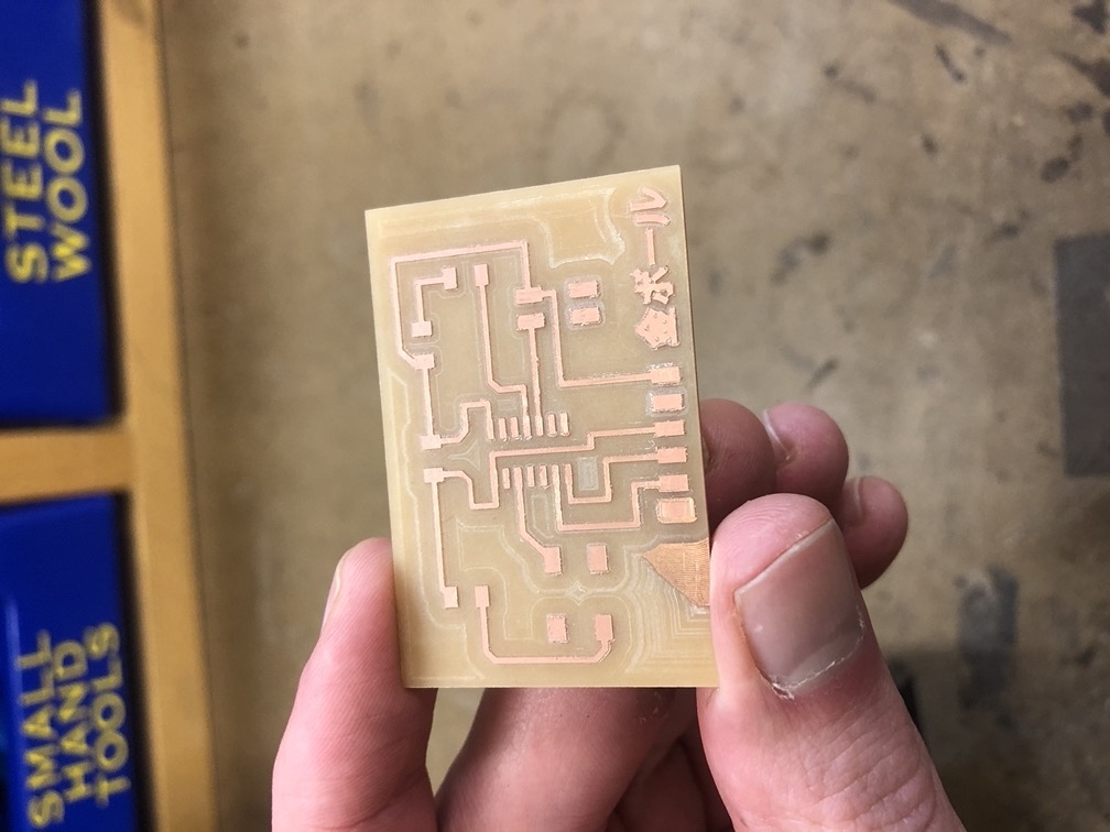
However, after trying out the fill setting to mill out all the extra copper, I have to say, it probably is not worth the extra mill time. Milling this board took about 45 minutes with all the extra passes. Also, after the board was finished there was this patch that didnt quite get cut through. I’m not sure if this was because the board was not laying perfectly flat or if the bit had shifted during the milling process. Either way, minus a few style points.
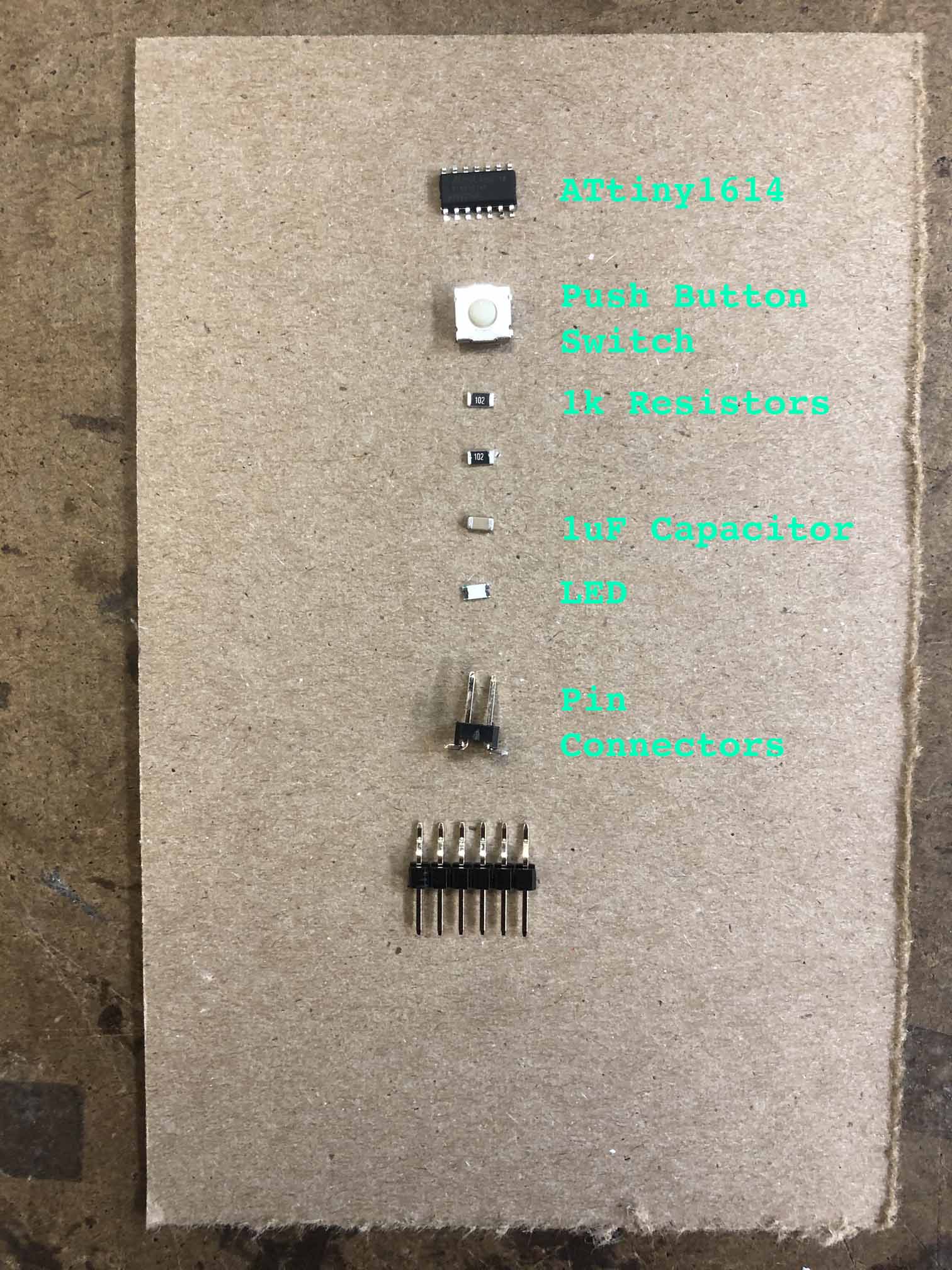
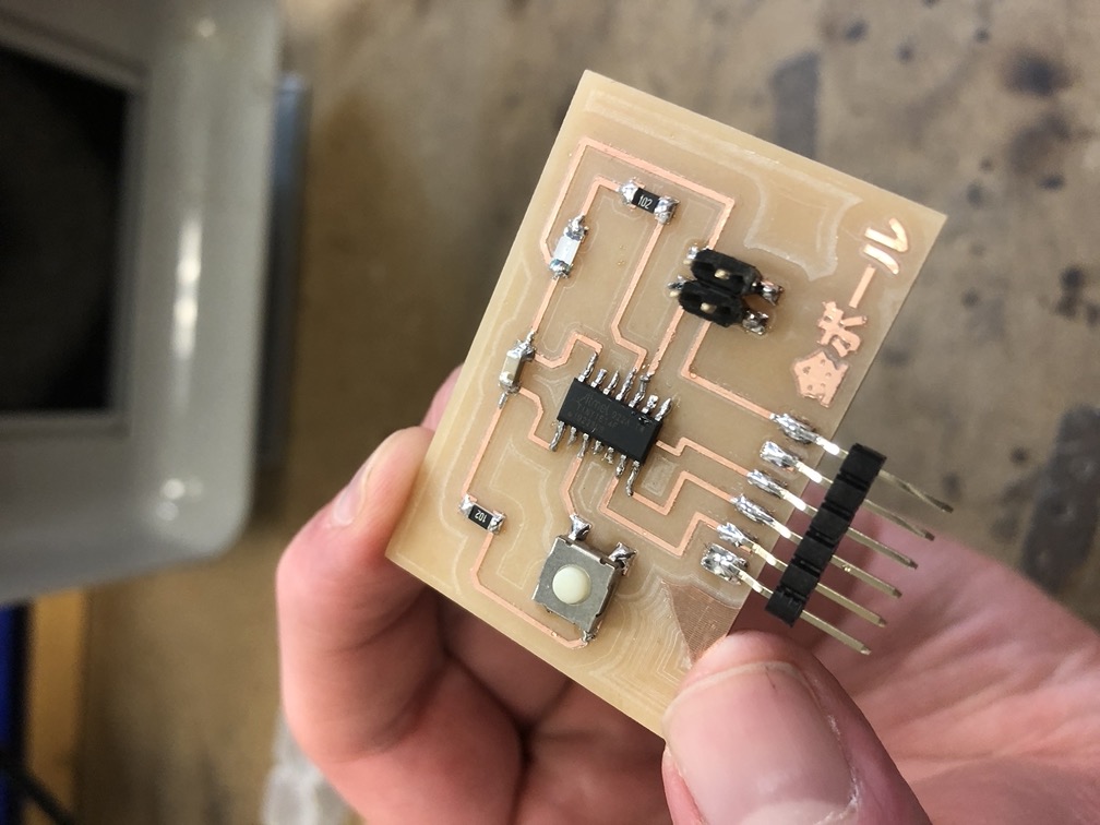
All that aside, it was time to start to get into stuffing this board. For this design, I used the ATtiny1614 as previously mentioned, (2) 1K resistors, (1) 1µF capacitor, a push button switch, an LED, and lastly the pin connectors.
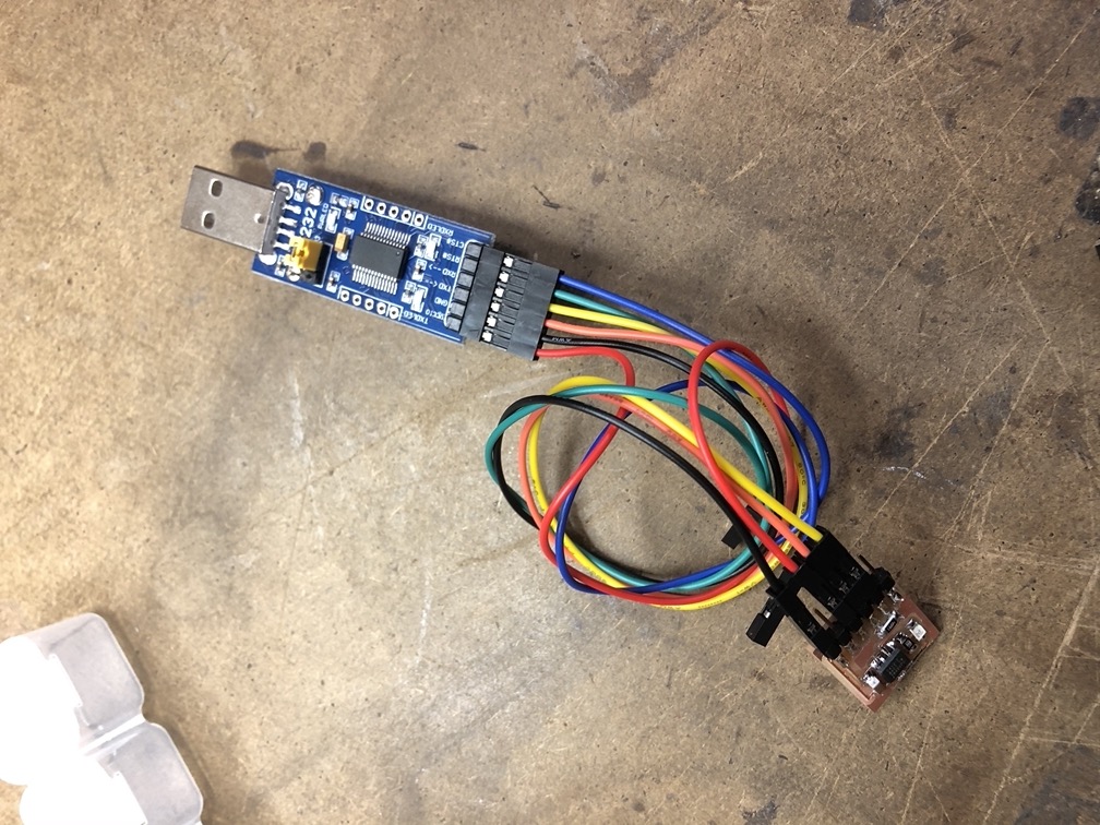
I used the architecture shop to do all my soldering. I have soldered before but only in the automotive setting, where things are much, much, bigger. It was difficult to get started and I’m not quite sure how well my results ended up compared to someone with more experience. However, I was thankful to have the shop be available during these times, and here is my set up. I was using the Weller we1010na soldering iron with a cone shaped tip at 600 degrees to start with some lead based solder.

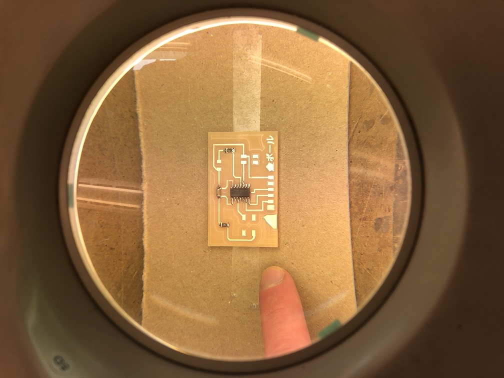
Also, it is kind of amazing how small everything is, and you don’t quite realize this until you see these parts in person...the magnifying glass is a requirement.
I’m not really sure the quality of the finished product, but here it is. I also must thank so many students and their accomplished pages with great documentation that helped me throughout this whole process. Thank you Maya, Justin, Marianna, Sophia, and Thordur.
Now onto actually programming this board to do something. This part I found a little more difficult to figure out, but I believe I have completed at least some of the steps correctly (as far as I can tell). For this part in addition to former class resources I used pages from Justin, Jordan, and Dave. I tried using the waveshare programmer that was included with our at home fab kit. I had to complete a few steps before I could attempt to load a program onto the board. First, I downloaded the MegaTinyCore through the Arduino IDE’s board manager (I already had Arduino IDE already installed), and then I also downloaded pyupdi and cloned the repository to my local so I could use the python script to upload a program. I also had to locate my hex file from the Arduino IDE and copy it over into my pyupdi.py location, which I actually copied over into my text editor to more easily find.
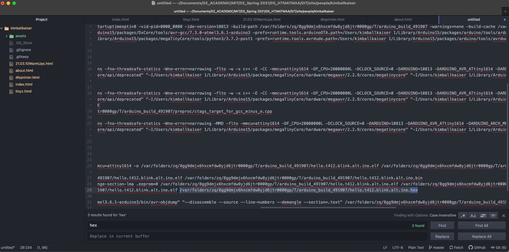
The next steps then included running pyupdi.p in the terminal. For me this was:
python3 pyupdi.py -d tiny412 -c /dev/cu.usbserial-AR0K4QSX -b 115200 -f hello.t412.blink.ino.hex -v
I should also note, because I did not have a 4.7k resistor designed into my board to program the pcb between TX and the UPDI pin, I attempted to solve this by putting a 4.7k resistor into a breadboard and connect it back to my board using jumper wires (which may have not worked, I am not sure...).
While I was ready to then start playing with my LED and push button, unfortunately, I kept running into this error which prevented that...: