21.03.25 DTS Printer Progress
The second project that we started to work on this week was configuring the various elements of making a DTS printer head for the Tiny Z. Some of the parts are a bit difficult to locate because of the HP C6602A Inkjet Cartridge. This cartridge was chosen as a starter because the wealth of documentation on it that is available. I have found this to be quite the resource while getting started on the project. However, because this cartridge is no longer in production, there some weird paths have been taken to acquire the parts. See in progress part list here.

Here is the cartridge in all its glory - note, ink may be harmful if swallowed. I bought these on eBay.
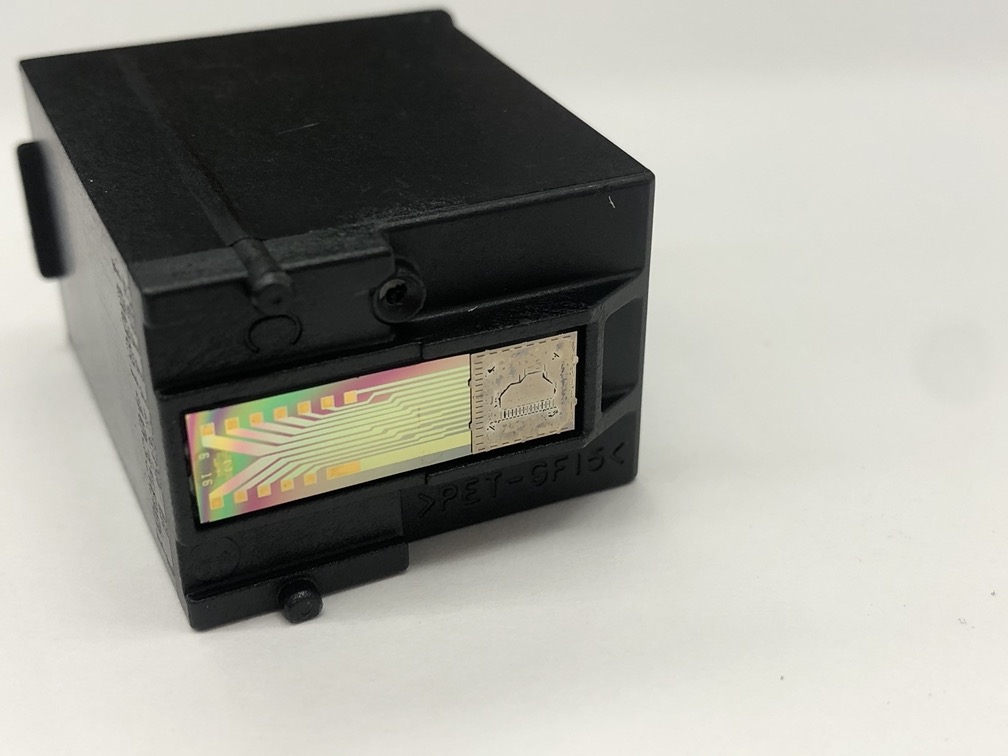
This is the underside of the cartridge where the inkjets and heating element are located. Essentially, how the printer head works (if I understand everything correctly, I still need to do some more homework on this sorcery) is electrical current is sent to each of these pins which releases ink from the jet. These pulses of current are at a high range, which documentation says safely is around 18v, however if this current is left on for too long, it ends up burning out the jet. Scary!
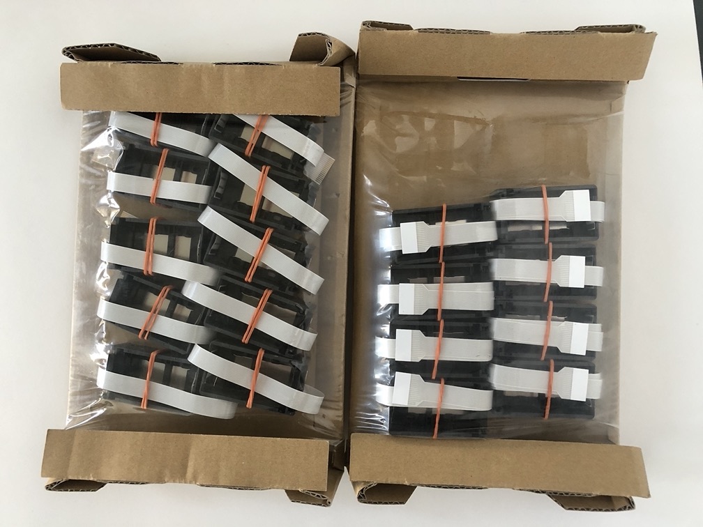
Here are the carriages for the ink cartridges that we will be using to hold the printer head. I ordered 1 qty, but apparently 1 qty means you actually get 20.
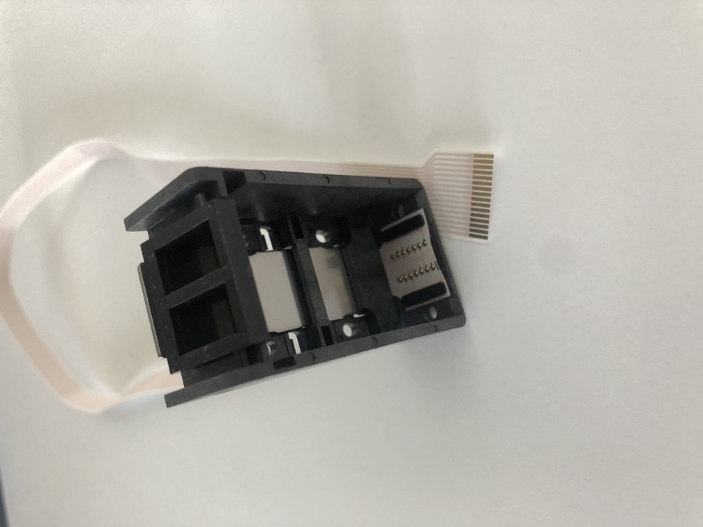
Each carriage has these very small connectors in the bottom that connect to each pin on the heating element. A flex cable then connects it back to what would be the printer. This cable connects to a FCC type connector. Finding this connector has been a huge trial and error process.

After trying a few FCC connectors, this was selected as a hopeful prospect. Especially because of the convenience of being able to pop out the cable, and because it already comes soldered to a PCB. The pitch of the cable is 1mm, however, when the cable is inserted and held in we still could not get contact for some reason. We have now ordered another FCC connector that hopefuly works and have jury rigged this one into working for the moment.
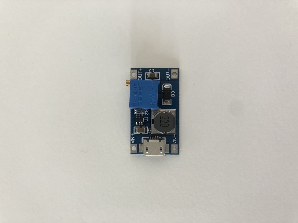
This is the step up converter that we have tried to use to boost our 12V power source to 18V.
Lastly, this is the transistor array that we will be using to connect each pin to the printer head. All of these components could probably use a little further research.

This is our crazy rat’s nest of a set up that we initailly tried out. This is wiring every pin through a breadboard to an Arduino UNO to try and use the printhead. Each Arduino pin has a corresponding printer head pin and then from online documentation we tried to run a program that someone else had written. However, after several varied attempts, it was unsuccessful. We believe we have wired everything logically, but also cannot be entirely sure about that. We also are unsure of some of things we are doing on the programming side of things. We will take one step back and just see if we can simply get one jet to shoot ink for the next attempt.