21.05.06 DTS Printer Progress
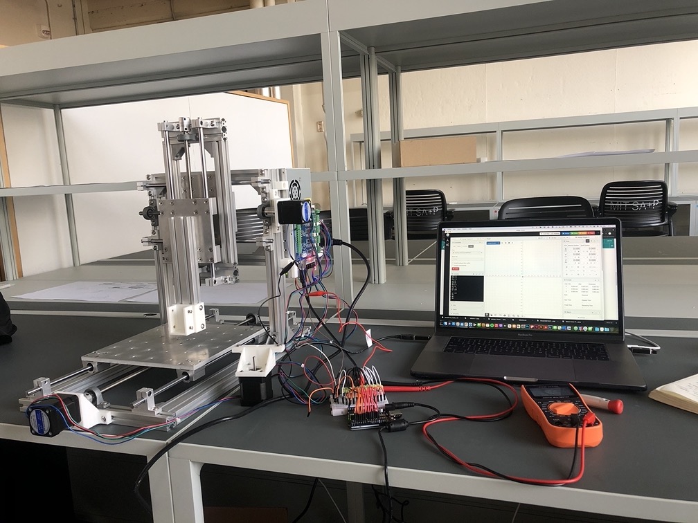
This week was mainly about configuring the printhead to run synchronously with the movement of TinyZ. Before, we were running both parts independently and we have explored an initial step of combining the two.
The first step was understanding the outports the TinyG board actually supports, and it is quite a bit.
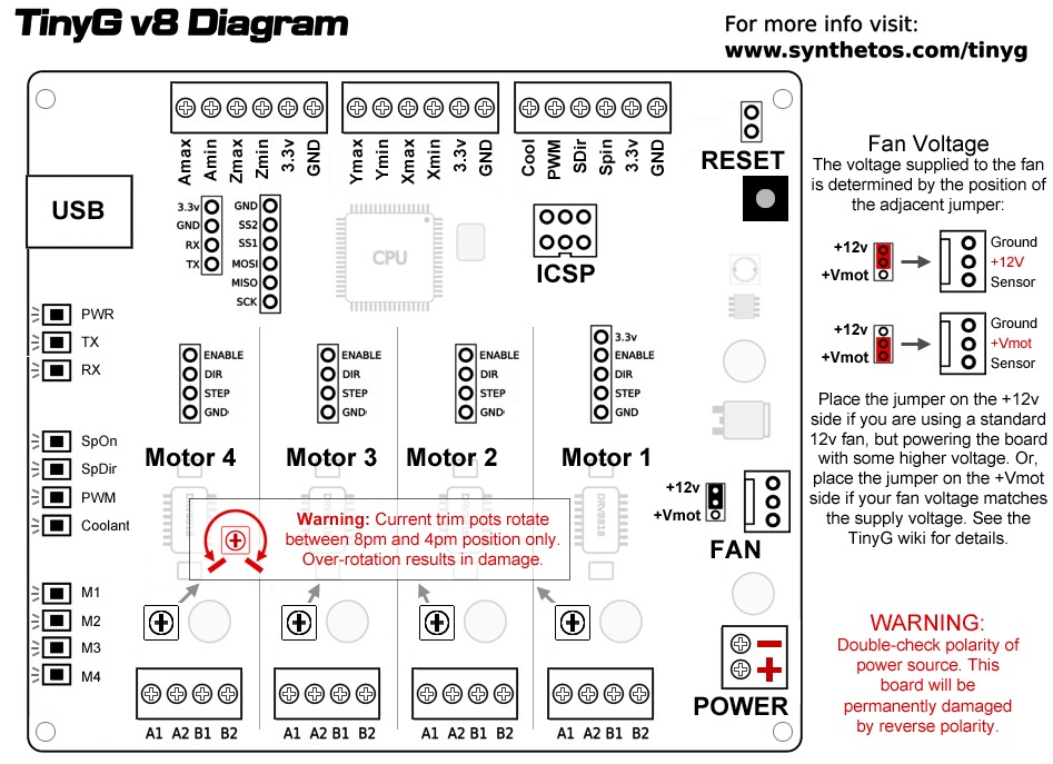
The TinyG board has 3 banks of outpins which can be seen on the top of this diagram of the board. These pins, as they are labeled, are meant to support things like a spindle, coolant, and a series of physical limit switches that can be attached to a CNC machine to avoid the machine from crashing into itself.
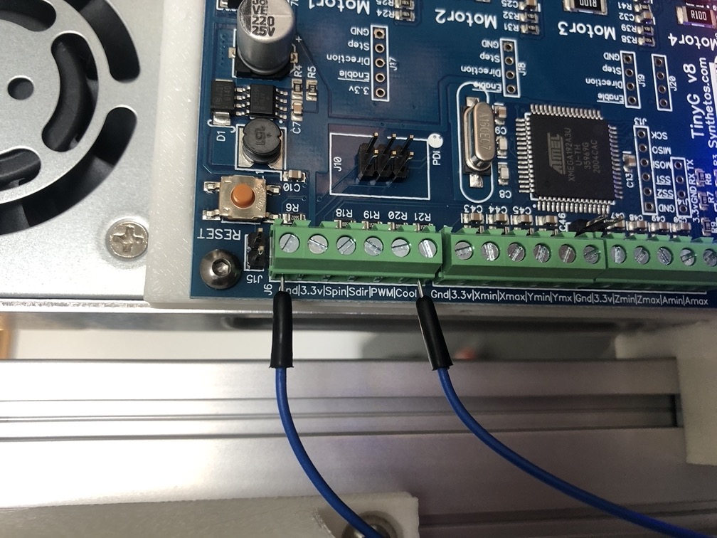
Here is part of our rather temporary setup for connecting the printhead to the TinyG board. As can be seen in this photo, we have chosen to go with using the outpin for "Coolant" which will be explained later on.
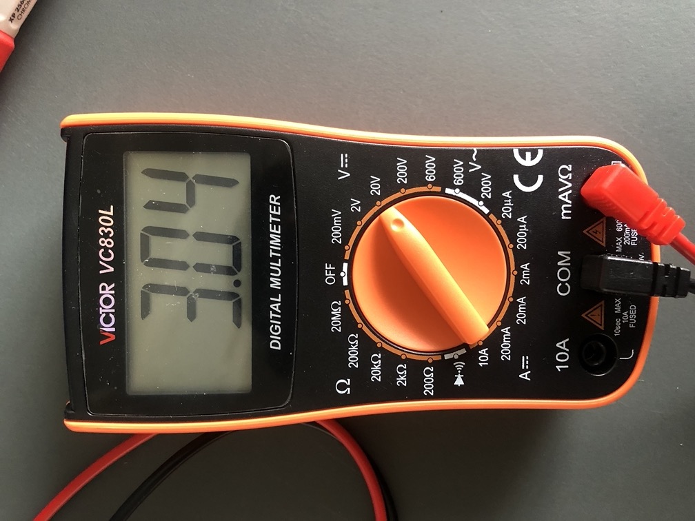
We can get 3V out of the the coolant pin when turned on. This 3V will then be directly led to our printhead setup to activate the code running our printhead. For some reason mostly unkown to me at the moment, when using the PWM and other various spindle control pins, we got much less voltage which would not be enough to trigger the internal pull up resistors in our printhead Arduino board.
Then, to get this 3V to trigger sending pulses to our printhead, we made some simple modifications to our printhead code to use the TinyG as an input to trigger running the pulses to the jets. See that code below (this is just running one jet currently):
To control our machine from our computers, we are currently using CNC Js, which can be found here.
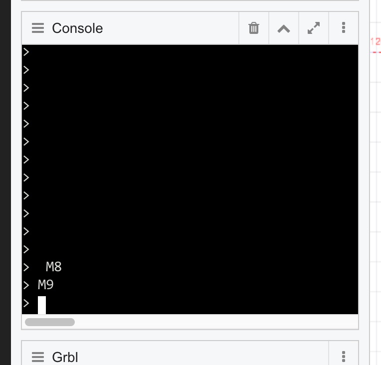
To actually toggle that coolant pin, the gcode for ON is simply "M8" and OFF is "M9." The tinyG cheat sheet for supported gcode can be found here.

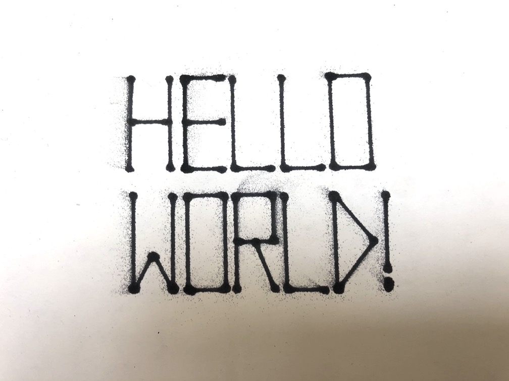
And with everything working correctly, this is what happens! In the gif above, you can see me controlling the printhead through the tinyG board coolant outpin, by typing M8 and M9 in the CNC Js console.
And with the printhead and tinyZ working together, we got straight to testing it with some real gcode.

First, as the most difficult geometry to draw by hand, we went with with the circle.

We then moved on to doing some test prints that involved more than one line, which would involve turning the printhead on and off between when the gcode is meant to draw lines and when it is meant to traverse to the next line.
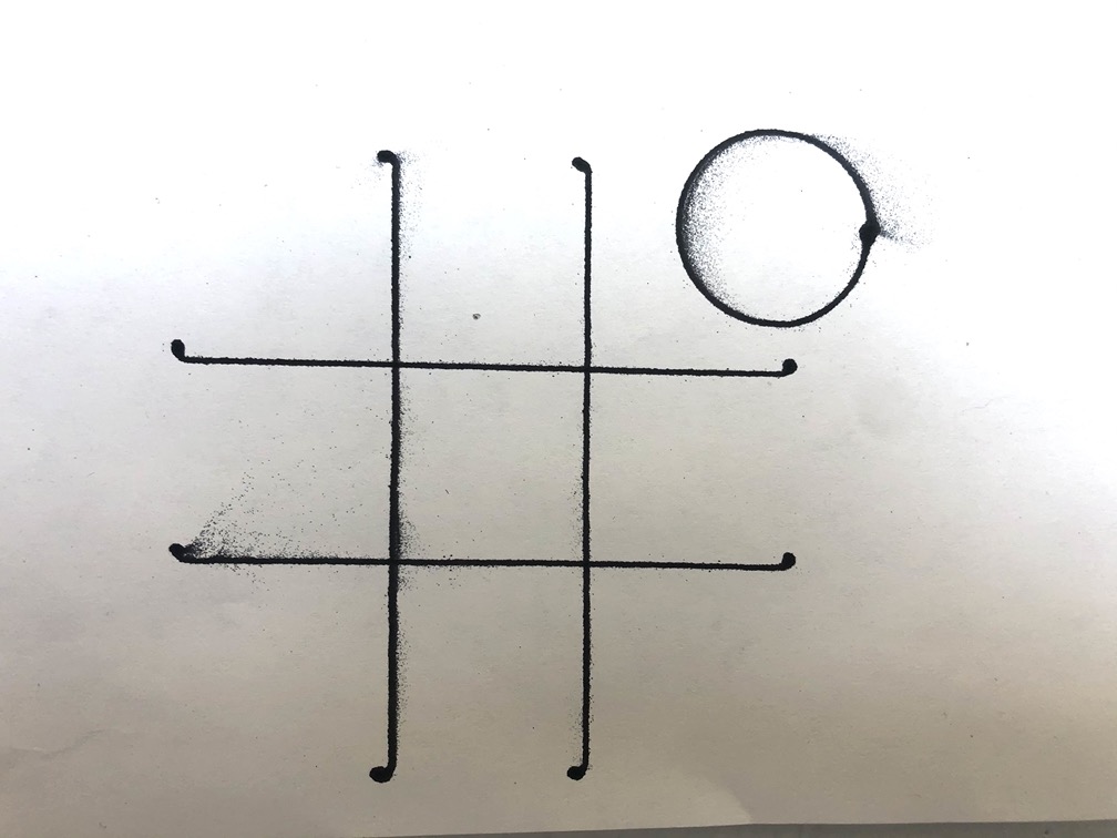
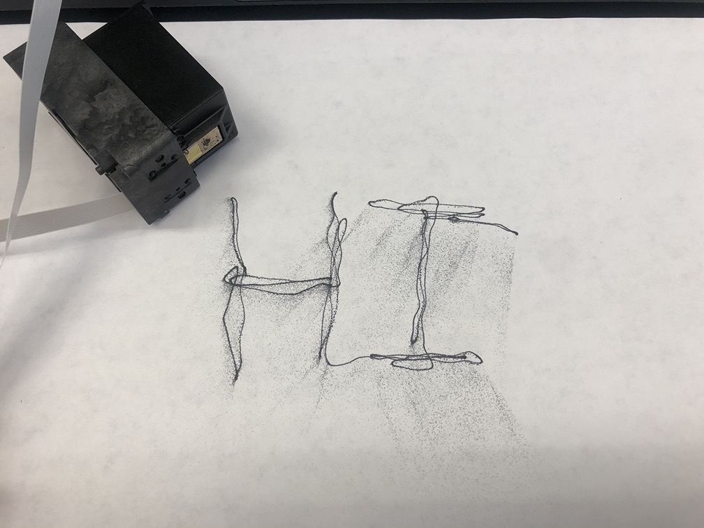
Here you can see some of our first print results. The circle, which is not absolutely perfect (yet) and a quick grid. There are hooks on the end of the lines because the gcode is acting as if we have lead in/out paths, which I will explain in a minute. Essentially we made an error for when the printhead should be turning on and off.
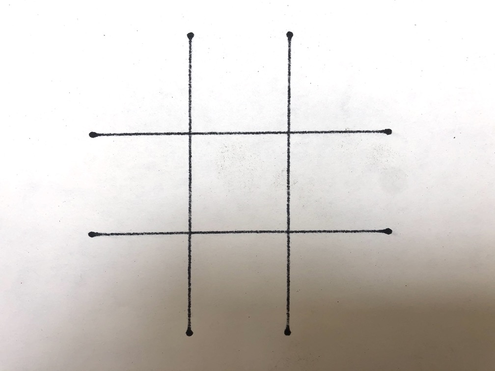
Here is that same grid with its gcode fixed.
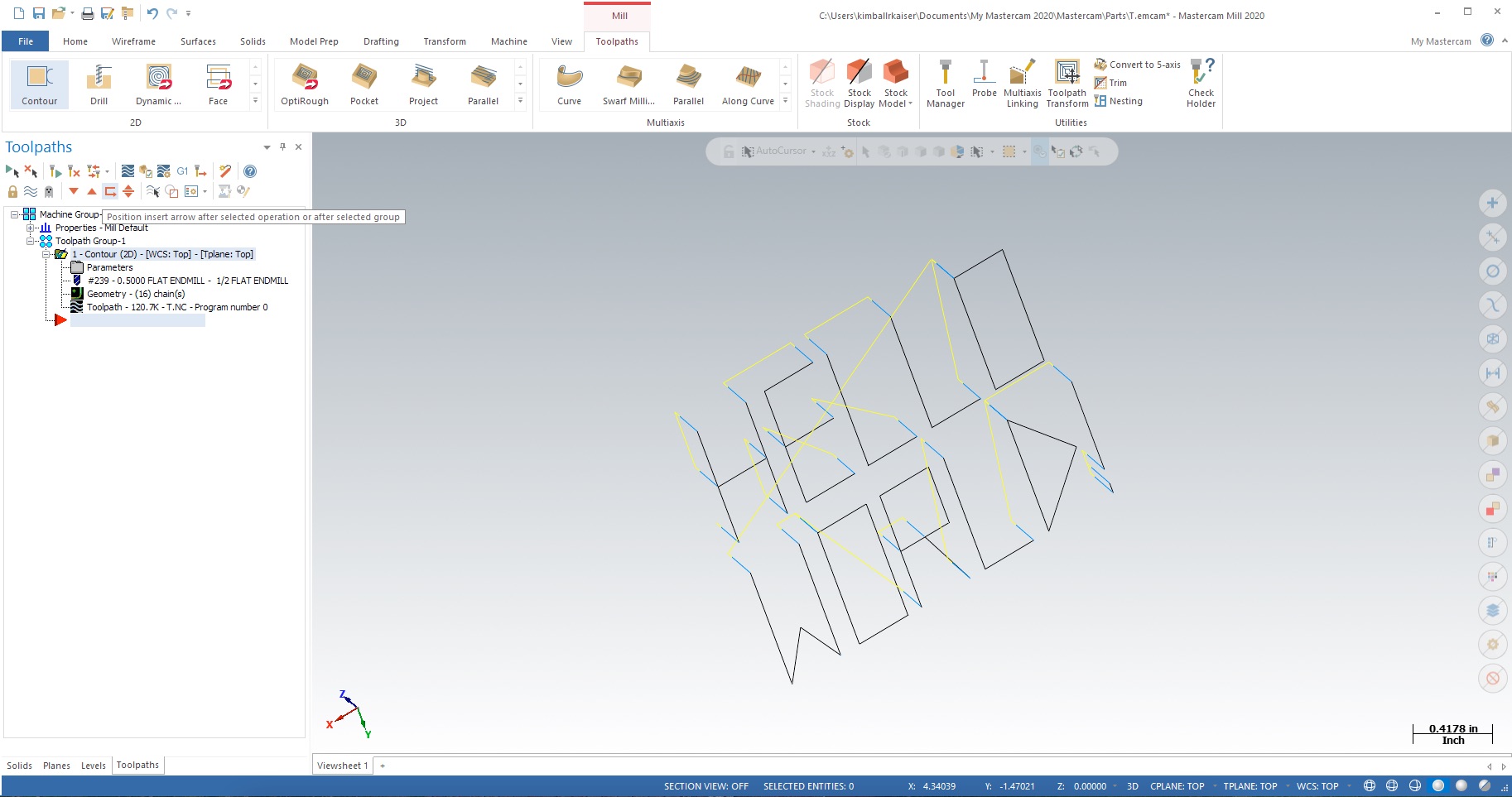
To make gcode for our machine, we are currently using Mastercam and just pretending that there is a spindle attached as an end effector. This part of the process will definitely be improved and we are currently looking into some more compatible alternatives. However, there are few nuances to making this work the way we would like. First, because for the moment we have disconnected our Z axis, Z in and Z out movements help us understand in the gcode lines where there should be printed lines vs traverse lines.
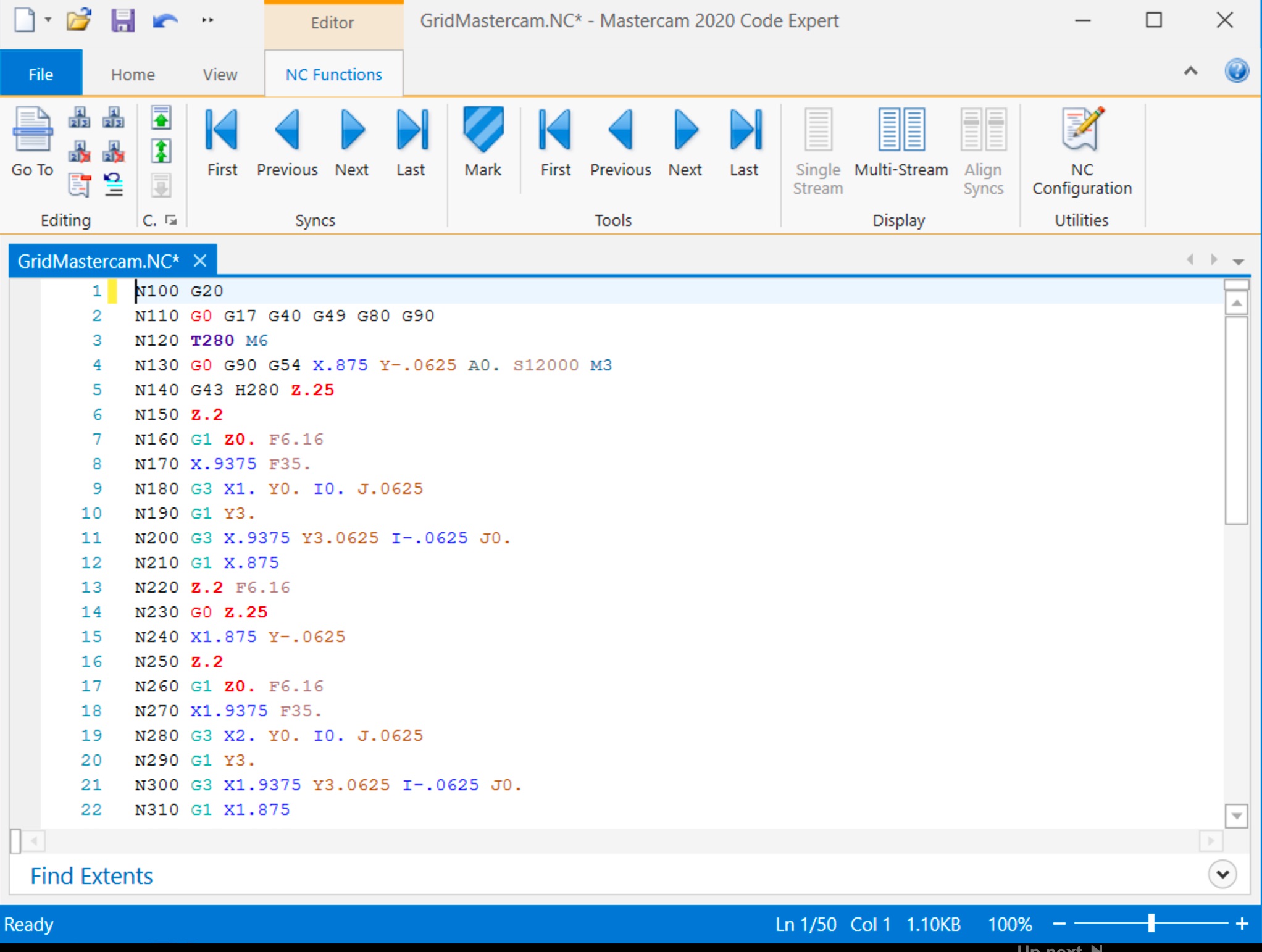
For example, in the gcode produced by this file above, these Z axis movements then give us a logic on where to add "M8" and "M9" for ON/OFF. Yes, this means to do these prints, we have been manually scrolling through lines of gcode, and guessing where our ON and OFF commands should go...see the example of our print gcode for this file.

This gcode then results in the print above. No, we definitely did not get it right the first time...Hence, this is why we are definitely working on a way to automate this process for ON/OFF.