21.05.13 DTS Printer Progress
This week we have begun to really test some of things we can actually make with our DTS printer. Along with testing our methods, we were interested in testing some of the limits and experimenting with what might actually work with our machine.
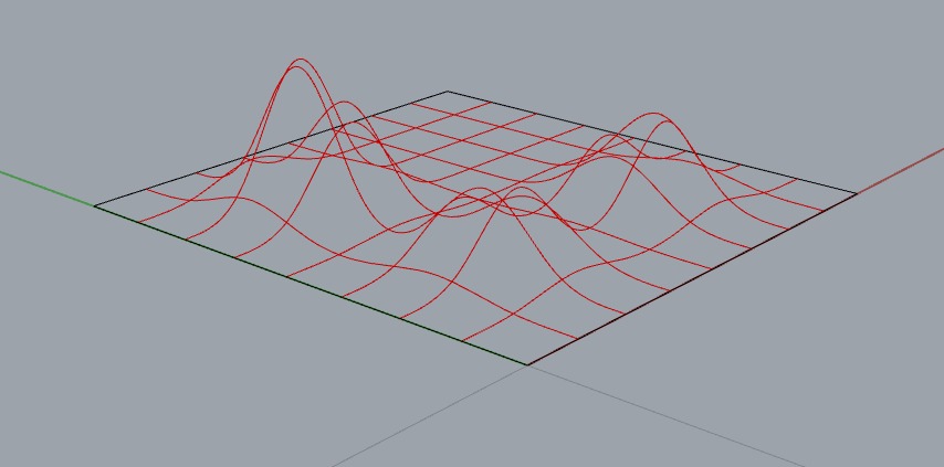
First, we were interested in what sort of printing effects we might actually achieve if we purposefully manipulate the z axis of the curves that we are printing.

We then printed a grid that is essentially applied to a surface that has been manipulated in the z direction. The idea was to see what kind of change in height produces manipulated lines.
See above for the results. The lines actually still pretty much remain even though we were varying the height of the printhead as much as 2" in the z direction. It is interesting to see how the overspray of the printhead jets actually work when moved further away from the surface of the printing substrate. It is almost as if the over spray only goes in one direction, which in this photograph, is relatively "up." For the most part, it is not so much that the line widths change, as much as the overspray effects change.

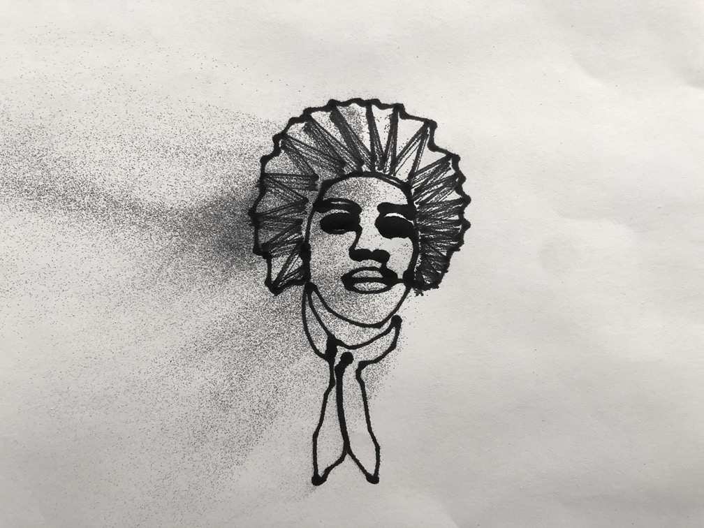
We also looked at doing a quick sketch where we might use a combination of lines and also scribbly like fills with our printhead. First, we tested out doing essentially a line drawing at a distance close to the paper for accuracy.

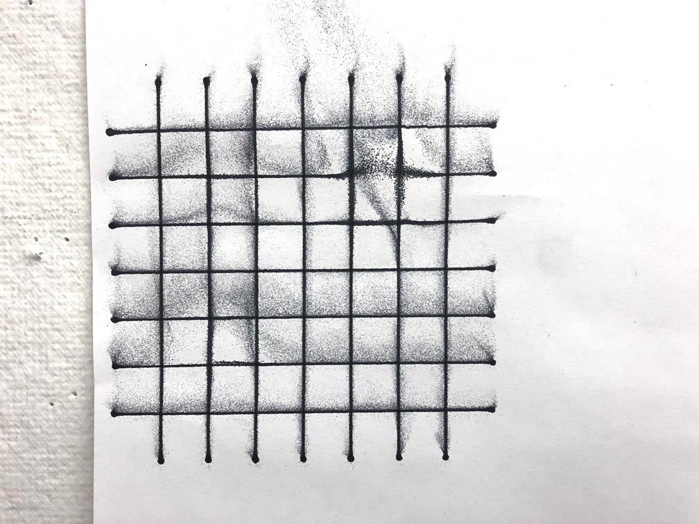
Then we tested doing a print at a distance further away from the paper, where we also used all 12 jets, thinking it might be somewhat like filling in the lines (maybe).

The source of the sketched portrait is this photograph of Jimi Hendrix.
And here is the result of the test...I apologize Mr. Jimi Hendrix...
We also looked at testing out a different end effector on the TinyZ, using our Dremel attachment to make it behave as a CNC Router machine.
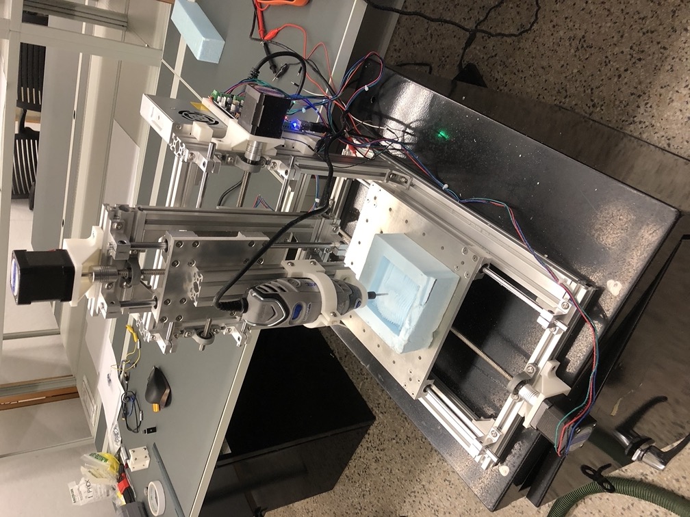
Here is the TinyZ with the Dremel as we routered some blue foam for our first routing test.

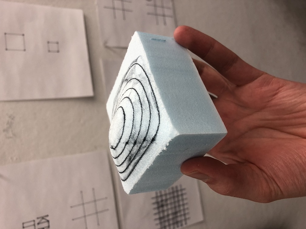
We started milling with rigid insulation, because not much rigidity in our machine is needed, and we used a very simple topo surface. We also just used one bit - a 1/8" Ball End bit.
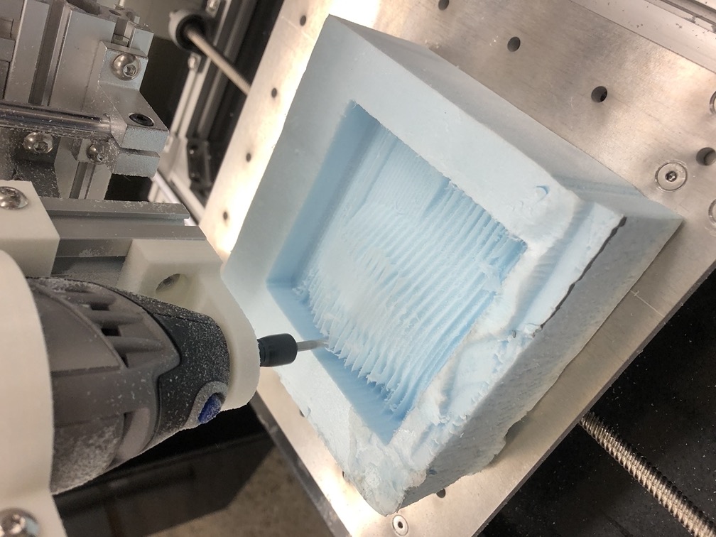
We also used Mastercam to produce the gcode for this mill job, and as can be seen from the photo, we probably should have decreased our step over distance between each path on the surface.

However, what we were really excited to do was print on a 3D surface with that same machine. We used paths spread across the 3D surface in space to produce a gcode that would allow us to print at different heights along this surface. This was an exciting moment for us!
It is challenging to figure out how to adjust the process to reduce the overspay widly spraying all over the 3D surface. However, we did also work on our mounts from the printhead to the TinyZ so that will reduce some distance from the ink jets to the surface. Although it is difficult to plan the print path with no collisions with the surface since the printhead is rather chunky itself.
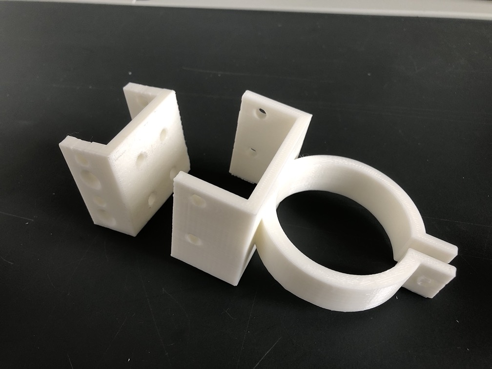
That being said, we also developed new mounts for end effectors since it is extremely cumbersome to repeatedly screw things into the t-nuts within the aluminum framing. The concept here is just to have a 3D printed part be permanently fixed to the aluminum framing, and have the end effectors connect directly to that.
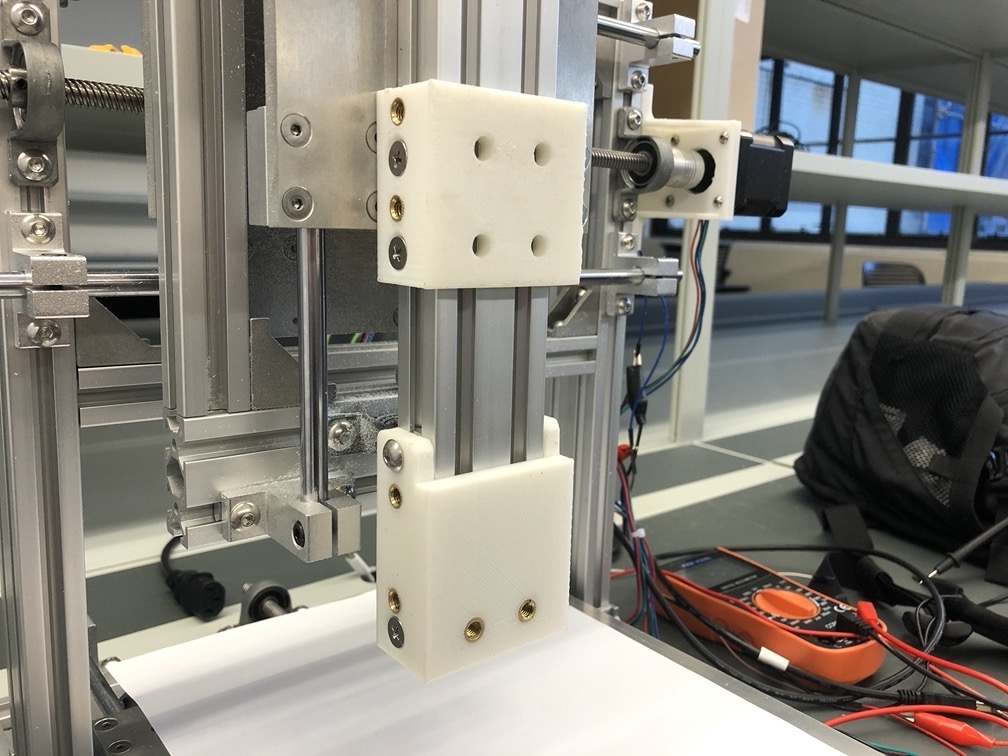
Here is the new 3D printed mounts attached to the aluminum framing. These parts have brass threaded inserts in them to allow our end effectors to be attached and screwed into place much faster.
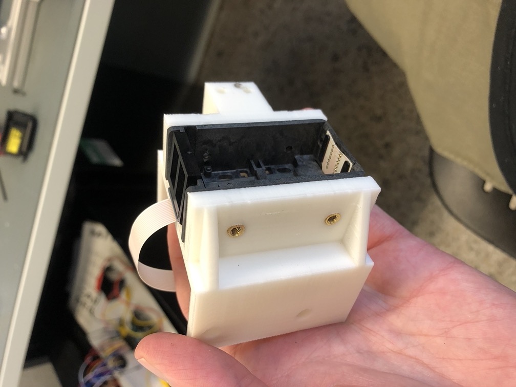
Here is the new carriage for the printhead that also screws into place and allows the printhead to pop in and out.

On this new carriage, we also added a spot to include a laser so that we can get a better idea of where to line up our origin point when making print files.
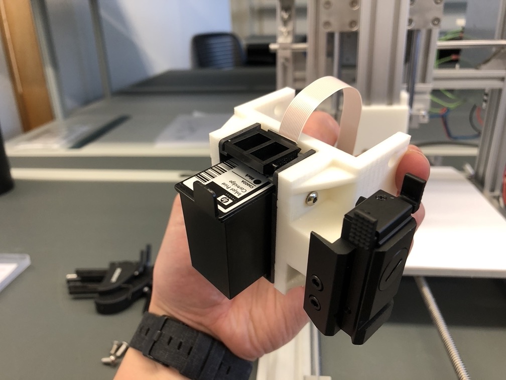
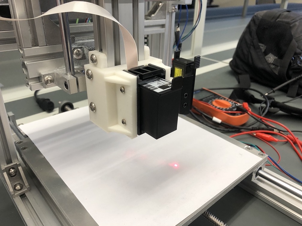
Here is how the whole system works - the carriage has the print head screwed into it, the carriage is screwed onto the mount, and our laser is on to help us orient our home spot for our machine!