Transmissions
We could also call these “design patterns” - just common ways of moving things about.
Belt
Probably the most common, belts (or more particularely for machines: timing belts) transmit force via tension, and index position using teeth.
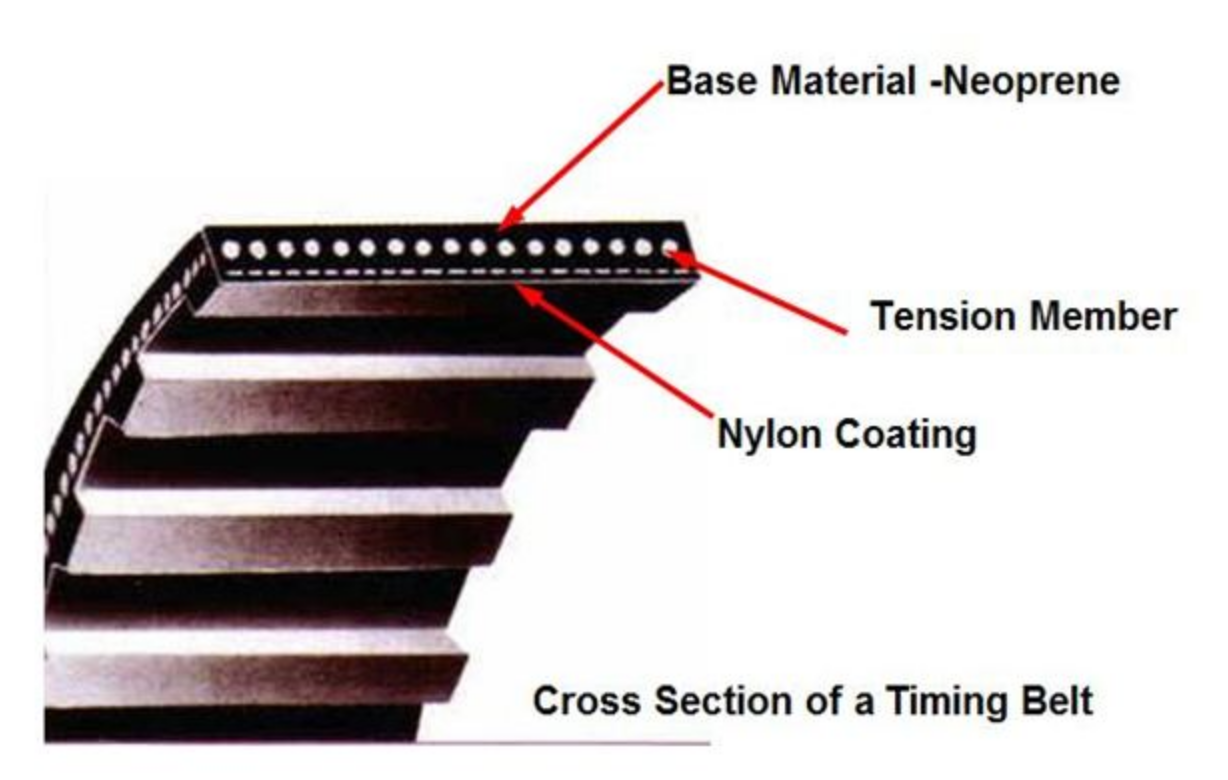
Belts have a “pitch” (the distance between teeth), and each have unique tooth designs. It’s often useful to be able to draw these profiles into CAD models to i.e. make belt clamps or custom sized pulleys, I have an example of how to do that up in the approaches section of this class.
“Standard” Pulley Layout
Most “fast” machines you find in the world will use this kind of design: it minimizes “flying mass” (i.e. the heavy motor is stationary) and is fairly simple to incorporate into a design.
For a different scale, the Zund:
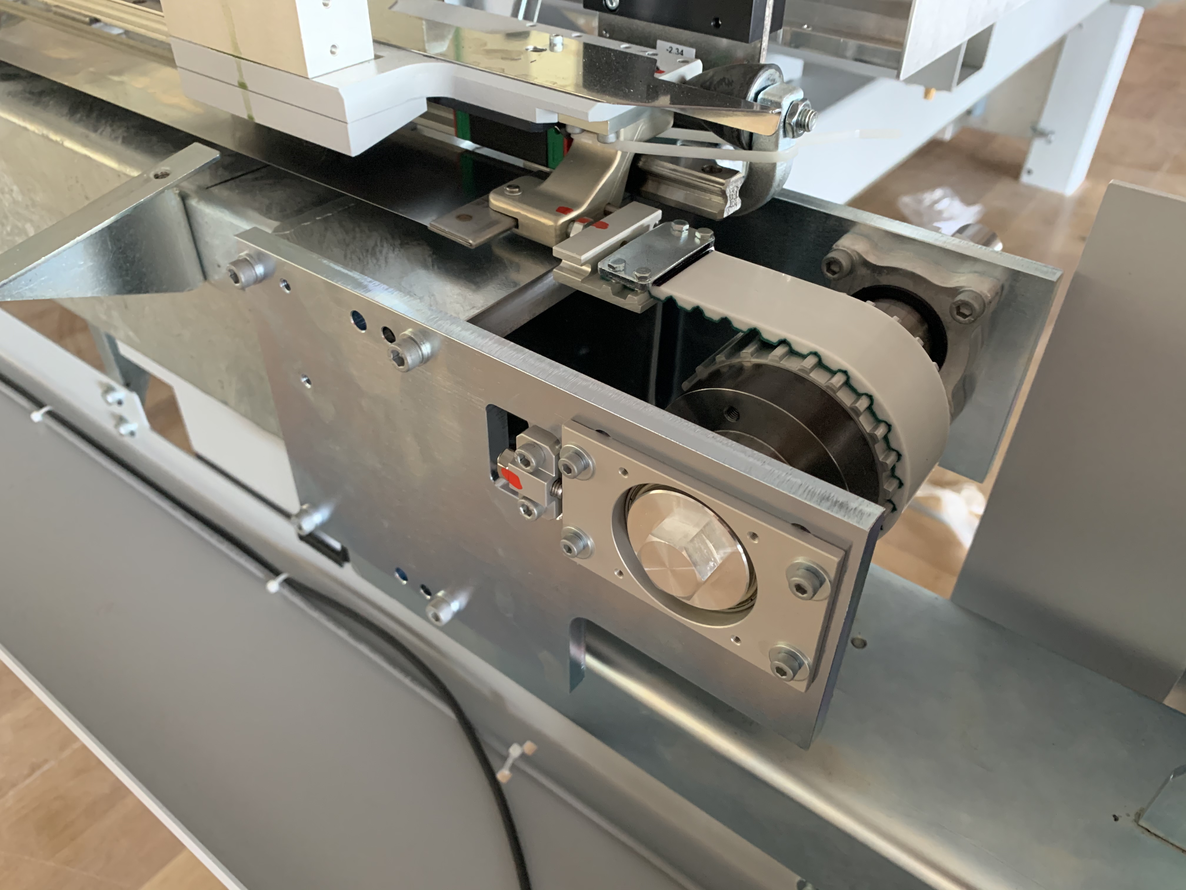
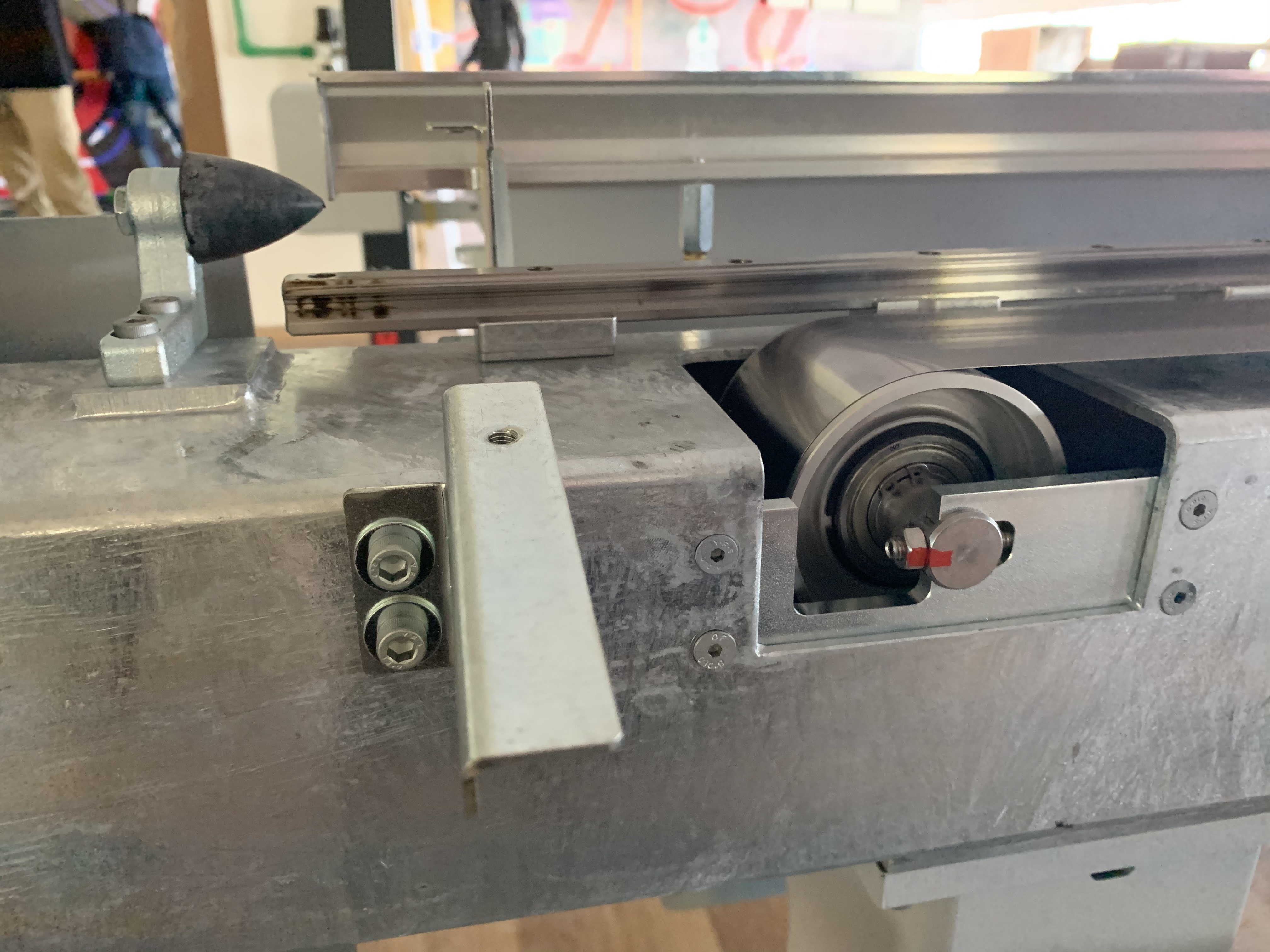
“Pinion” Pulley Layout
These are favoured sometimes as they can increase belt stiffness by about 2x (as the length is halved). They can also be easier to implement, have less tracking issues (see below), and sometimes simply “fit” better into a machine (i.e. this is a way to move the motor around in layout).
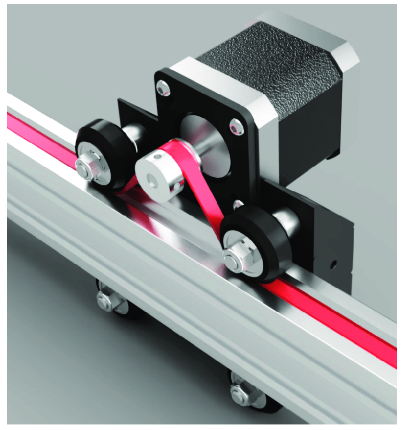
a note: I will say I am a bit irked by Open Builds’ use of linear rollers to double as idlers, however it does reduce cost & complexity.
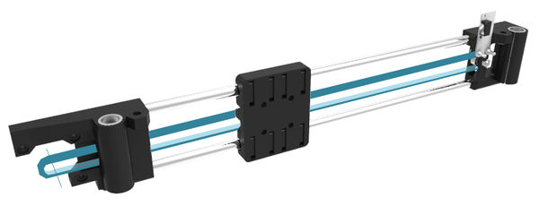
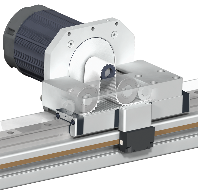
The implementation below (though patented) uses two belts that mesh with one another at the idlers to increase stiffness 2x again:
Consider
tensioning
Keep in mind that belt tension is critical to a quality drive and that your tensioning device is also part of the structural loop and so a good detail design of your tensioning device is critical if you want this to work well.
clamping
Firmly securing your belt to the machine is another critical juncture: if this connection is not stiff, your machine will not be stiff. There are a handful of ways to do this, and if I have time I’ll return here and document a few of them.
tracking
This refers to the motion a belt makes along the axis of it’s pulley / idler and is important to consider in high-quality belt drives.
![]()
Screw Transmission
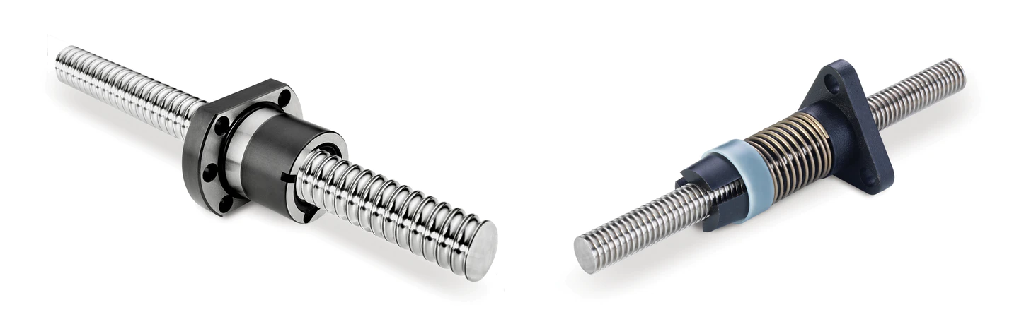
Leadscrew (cheap, higher friction) and ballscrew (expensive, lower friction) drives are the “standard” for high quality motion (that doesn’t need to be blazing fast) and typically go along with COTS linear carriages, like this:
Screws also have “pitch” that defines how many units of forward motion occur with each rotation, and have an integer count of “leads” - how many “starts” the screw has.
Screws can make for great high-force transmissions when the pitch is small, and also great high-speed transmissions when the pitch is large. Ballscrews, being low friction and high stiffness (consider the cross-sectional area of a screw vs. that of a belt), are the most common drive in modern “high performance” machines. However, both ball screws and the linear rails they work alongside are items where we simply pay for precision.
Consider
The classic layout for these drives (two linear rails, one lead or ballscrew) are over-constrained: both linear rails and the ballscrew constrain a complete axis of motion, so when assembling we have to take care to ensure that they are well aligned, as takes place in this video. We typically do this with alignment jigs (like long parallels) or with machined-in alignment features on the structure they are mounting to.
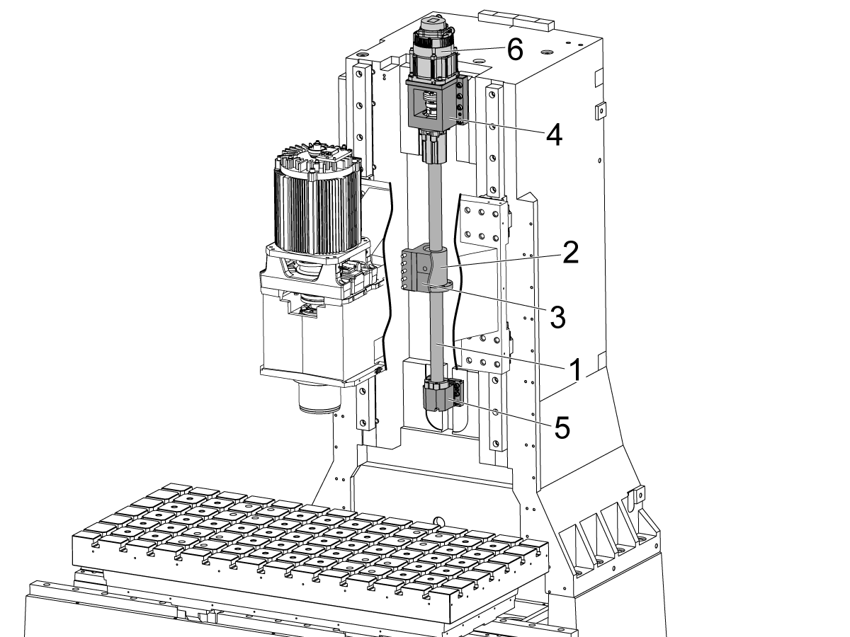
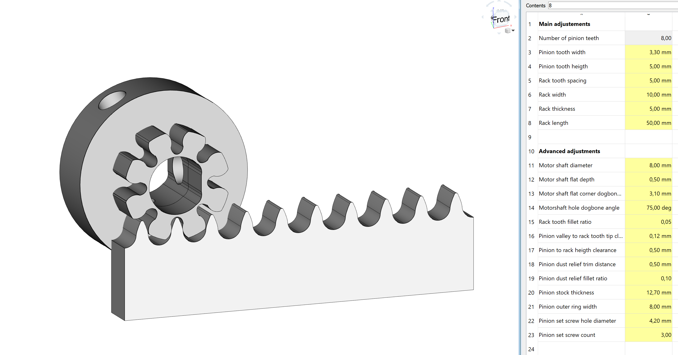
Rack and Pinion
These drives are common on larger, stiffer gantry machines (shopbot included).
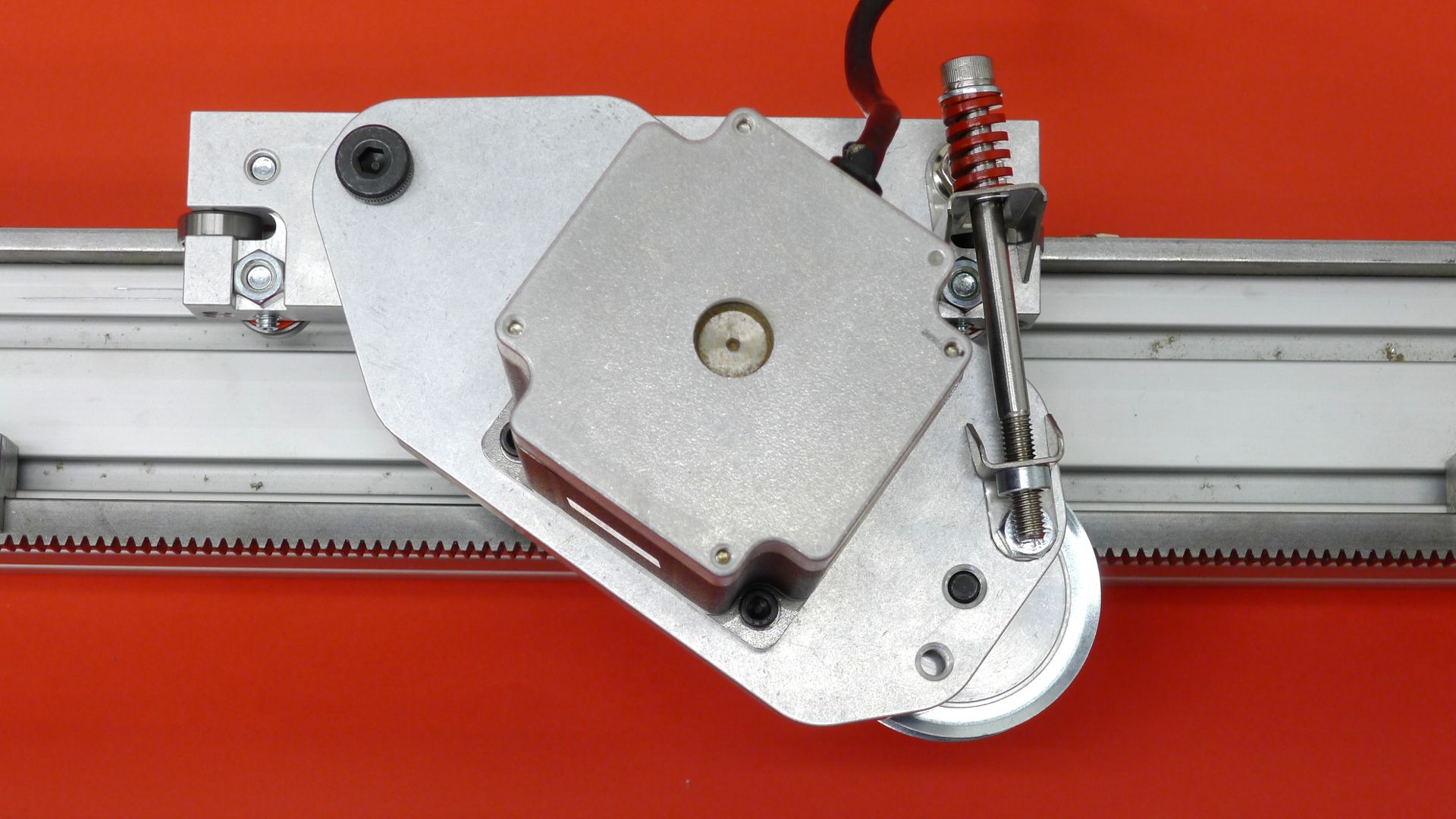
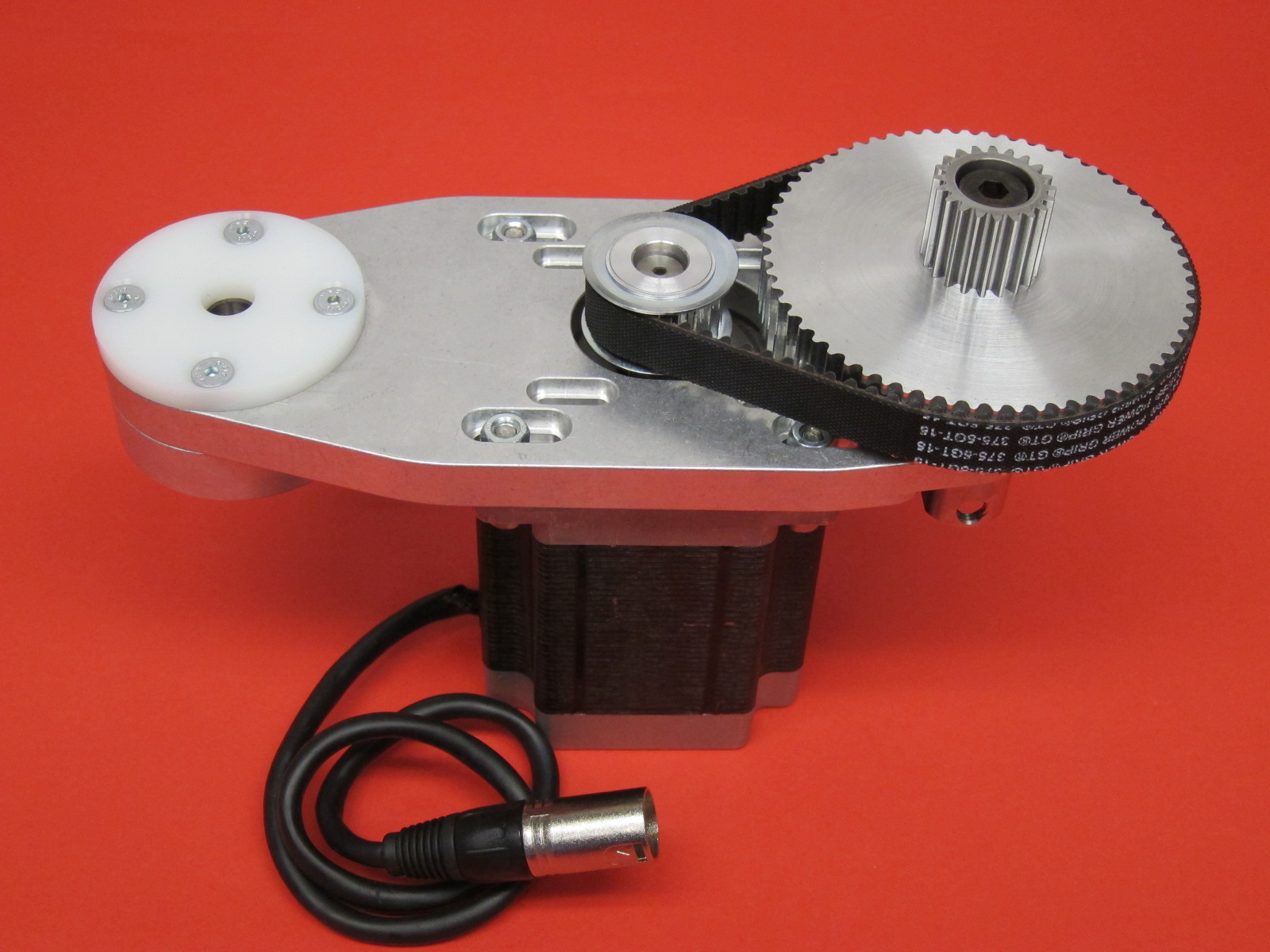
While stiff, these can be tricky to preload and often require an additional reduction between the motor and pinion to achieve the desired force output. Additionally, manufacturing racks can be troublesome (but often worth it) or expensive. In terms of setup, though, and design nuance, these are fairly straightforward.
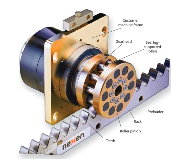
We also have more modern “roller racks” where we dont’ have involute teeth engaging involute teeth, but rollers engaging cycloidal teeth:
These are similar to Jens’ machineable rack-and-pinions:
I spy on Jens’ website another exciting development:
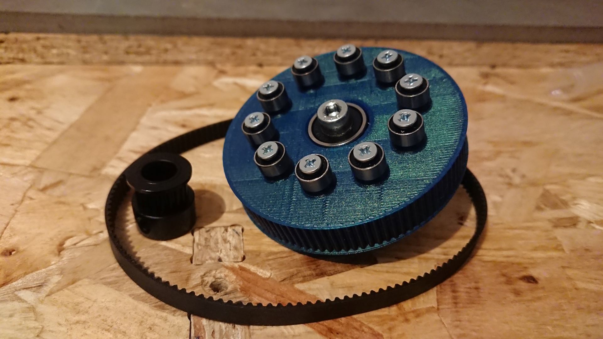
Both from here, where Jens also documents the pros / cons / lessons learned from manufacturing these.
Consider
Like in the lead / ballscrew, our rack also defines a linear axis of motion (along with the linear guide it presumably rolls on), and so if our rack and guide are out of alignement, the rack’s tooth mesh will change slightly during the course of travel.
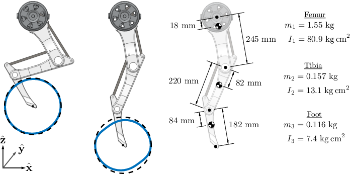
Capstans
Dear to my heart are capstan / wire rope transmissions. These are more common in “well-defined” (as in, not continuous rotation) rotary axis, like robot arms etc:
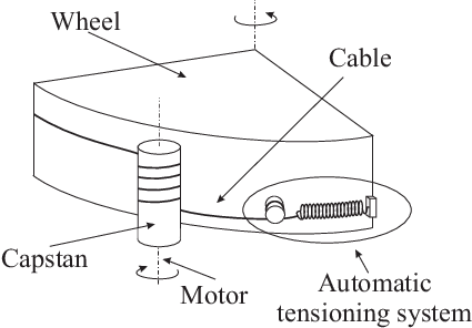
With a capstan, we use the capstan equation or more accurately the friction it generates in order to transmit rotary force into linear “pull” on a wire rope: relatively stiff tensile members.
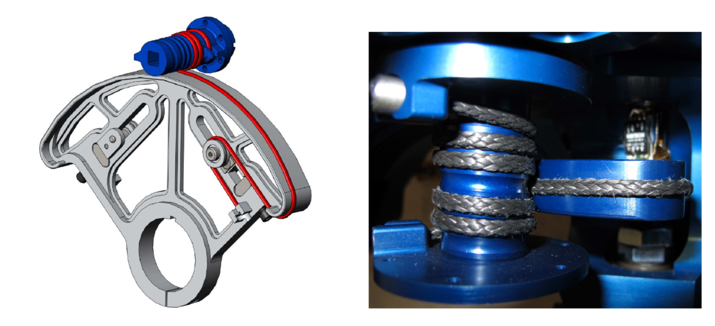
Notice that the wrap along the capstan is set in a fixed helix: we cannot use these exactly like pulleys, as the wire rope “walks” up-and-down the length of the capstan during actuation.
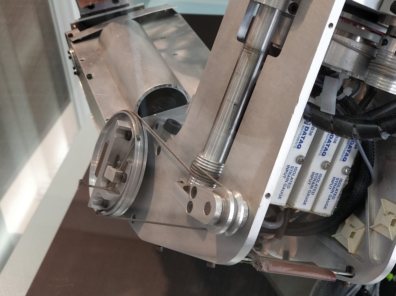
Terminating wire rope ends is also of critical importance, as the capstan equation only works when positive preload is present.
I tried for a while to make machines like this, and I still think the approach is promising for very high-performance drives, but wasn’t going to work with a majority 3D Printed components (consider esp. a lack of concentricity on a captan, and steel wire rope’s limited ability to stretch).
Planetary Gearboxes
Planetary gearboxes are relatively small size for high reduction. You’ll find them in a lot of components: they are also the standard gear topology for i.e. power drills and drivers, and most automatic (car) transmissions.
We typically see the “sun” gear as an input, and the “planets” are attached to an output (via their shafts).
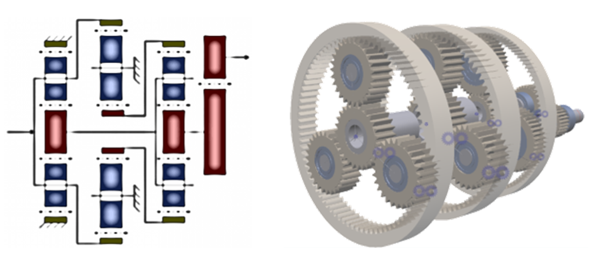
Keep in mind that these normally present noticeable backlash, unless you spend a lot of money (or time) on a precision set, where you will find only very little backlash.
Harmonic Drives
These are the beating heart of most robot arms, originally developed for the lunar rover in the 1950s. They use a ‘strain wave’ gear and ‘strain generator’ … it’s best just to watch one to understand:
These are possible to make at lower cost i.e. with a printer, but are limited by gear meshing properties of plastics (not good) and load carrying through the thin strain wave element (also not good in plastics).
Jens has also been able to mill one of these:
Cycloidal Drives
Similar in principle to a harmonic drive, these use a “wobbling” rotor that engages rollers around the edge sequentially:
Complexity arises from bringing the “wobble” output back to a plain rotary output, but these can also be made with i.e. 3D Printed components at a typically higher success rate than strain wave gears (as we don’t rely on material flexibility). Precision of the gear and roller profiles is paramount.
Keep in mind that with high reduction drives we are often concerned not just with total reduction but also with the quality of motion that they deliver: whether it is highly linear or not.
Guides
I’ve talked a bit about transmissions but not so much about guides. These are ways of constraining (typically) linear motion so that just the DOF we want loose is left unconstrained.
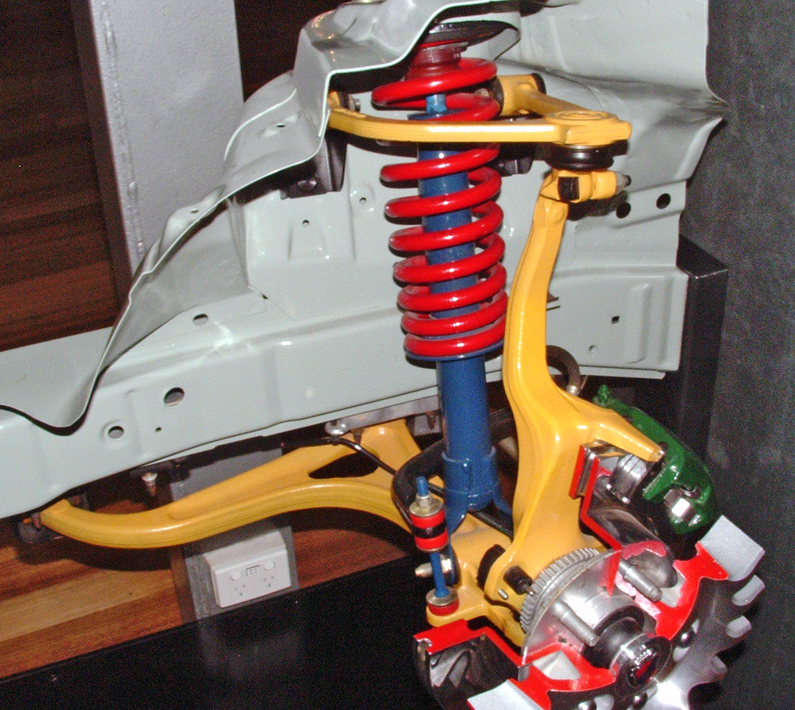
Ways
The OG linear guide, “machine ways” are often simple i.e. dovetails cut (and then scraped) into cast iron or steel machine structures.
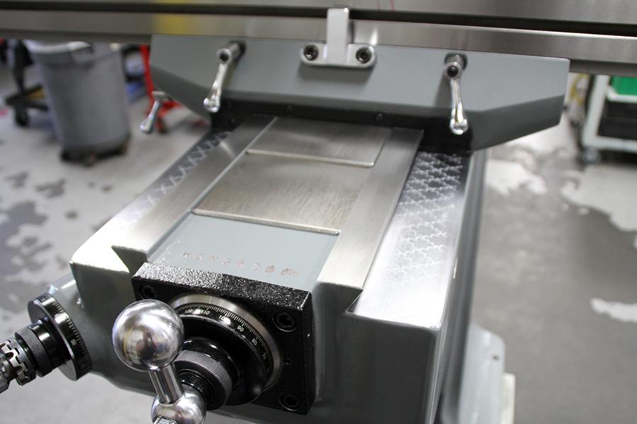
Extremely overconstrained, very precise fabrication required. Technically “hydrostatic” bearings: ways run along a film of oil at contact.
Air Bearings
Typically coupled with linear motors (for motion & preload), air bearings float on a thin film of compressed air.
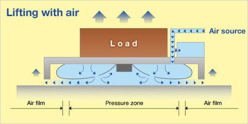
Basically: air hockey tables, but extremely precise. As the air film becomes thinner its stiffness increases dramatically. So, to play the air bearing game we have to bring big precision (typically in the form of flatness) to the table.
However! These can be cheap to build, as our very own David Preiss shows:
Linear Carriage
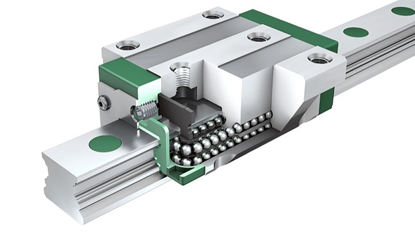
- stiff!
- expensive (but less so lately)
- low friction (it’s a ball bearing)
These are rad, caveat is that you can’t choose length, and unless you order from a “real” manufacturer, specifying i.e. preload is near impossible and / or you will get batches of parts with varying performance. This means that using cheap linear rail is possible for one-off projects (where you can tune, or pick from a batch), but is less possible when you want to make thousands of a product and still pass QC.
Linear Shaft
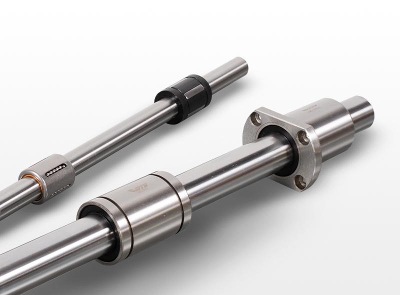
- often ‘simply supported’ beams of questionable depth: not very stiff
- cheap(er) but still difficult to get exactly the right length spec
- i.e. this means we often end up designing machine size to suit available rail lengths, not the other way around. often this is OK
- (can be) low friction, same caveat as with linear carriages applies
- can be used with roller (recirculating ball) bearings, or simple i.e. bronze or ptfe bushings
Roller Rail
Here we align some rollers (probably bearings) along a rail / structure:
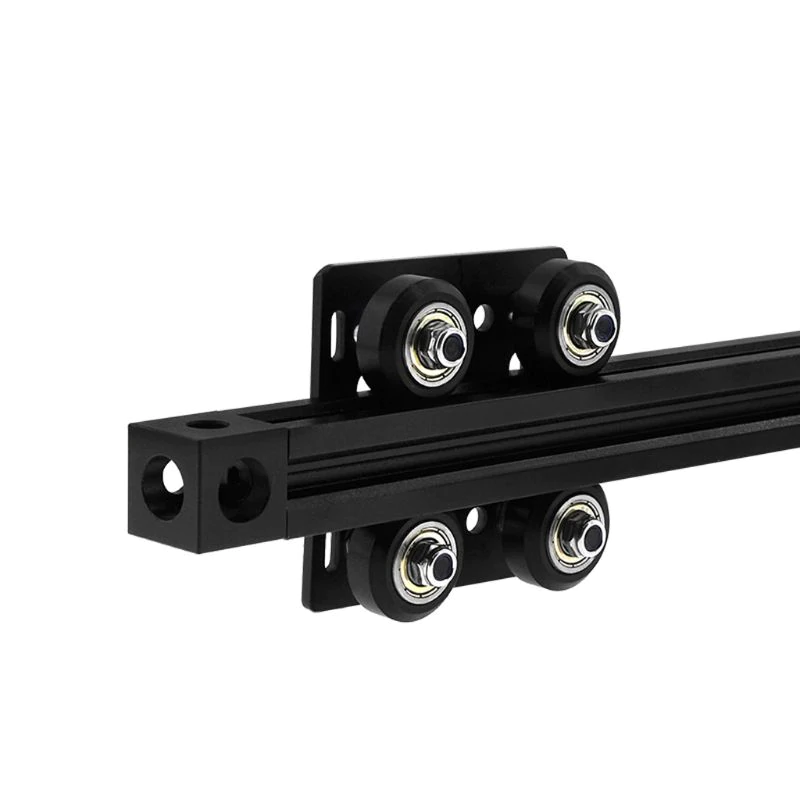
from OpenBuilds with proprietary extrusion
- cheap
- any length you want
- design-your-own preload
- fairly robust
clank is all roller rail.
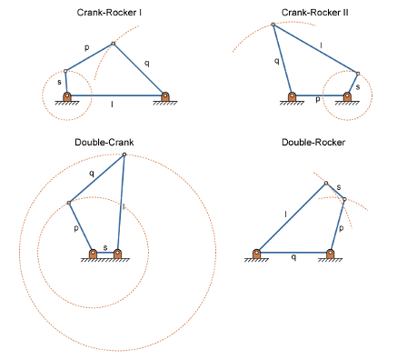
Linkages
- it’s levers all the way down
- structure & mechanism, together at last
- possible to simulate in most CAD packages
- consider backlash at each pin joint
- consider nonlinearity of motion
- simple linkages: often very useful
- complex linkages: often very interesting
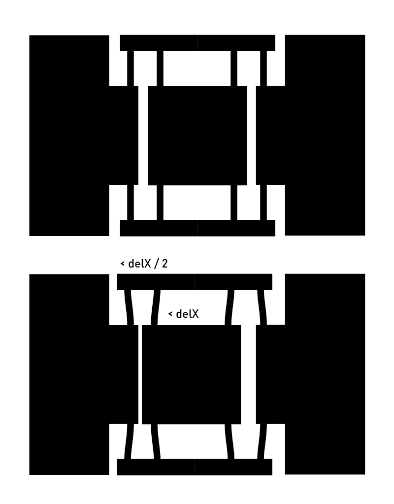
Flexures
- any linkage-type mechanism, but with extremely small, zero-backlash deflections
- flexures are for nano-positioning / small stuff
- Dan Gelbart is one of the GOATs
- actually (except for stiffness) zero backlash
- large machine size relative motion
- strain must be small
The basic design pattern for a one DOF stage is here:
This can of course be expanded into multiple axis and we can use flexural beams as kinds of linkages, as Zach can show.
Flexures are very cool! They can show up all over the place, you can put them into anything very easily (i.e. for the adjustments I mentioned earlier: flexures let you make zero-cost mechanisms). If you want to do a deep dive, see amy makes stuffs’ hackaday lecture.