BLDC Modular Thing 8-60V
Description
You can use this board for easy Field-Oriented Control of a sensored brushless DC motor. The motor knows its position and automatically returns to it when disturbed. More details are in this thread on the SimpleFOC Community site.
The ultimate goal is to integrate this board into the modular-things ecosystem. I haven't got that part of the code working yet, but you can use this board as a standalone BLDC controller.
The board requires a separate power supply for the motor. You could use a bench power supply or hack USB power with a tiny412, for example.
This board works well, although thermal management could be better. But I'm prioritizing that the board can be milled in a Fab Lab. It's based on the SimpleFOC Mini and the DRV8313 datasheet.
The board is designed to control iFlight gimbal motors with integrated AS5048 magnetic angle sensors.
You need a V-bit to mill this board because of the small pads for the DRV8313 motor driver.
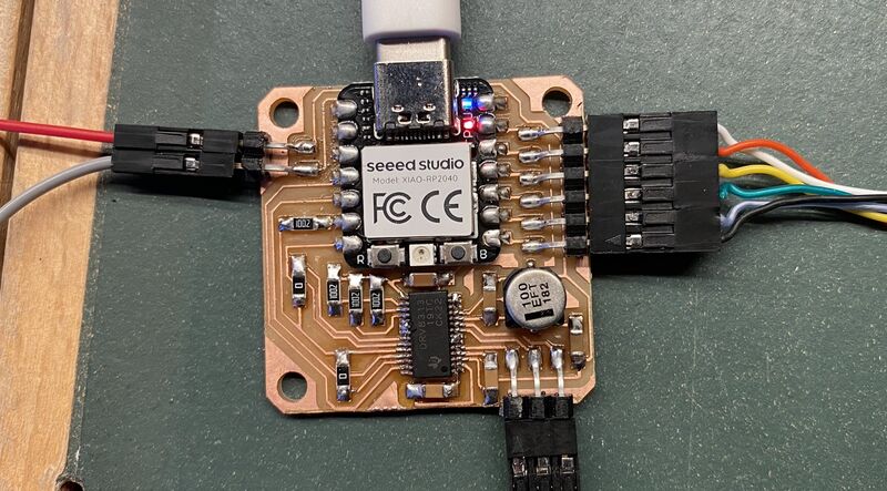
 On the left side of the board are two pins for an 8-60V power input. The motor output pins are on the bottom of the board and six SPI pins for the sensor are on the right side.
BOM
| Part | Count |
|---|---|
| GM2804 Gimbal Motor w/Encoder | 1 |
| Xiao RP2040 module | 1 |
| DRV8313 motor driver | 1 |
| 100 nF capacitor | 4 |
| 1 uF capacitor | 1 |
| 100 uF bulk capacitor with 6.3 mm diameter | 1 |
| 0 Ohm jumper resistor | 2 |
| 10 kOhm resistor | 4 |
| 2 pin horizontal SMD pin header | 1 |
| 3 pin horizontal SMD pin header | 1 |
| 6 pin horizontal SMD pin header | 1 |
You aren't restricted to using the GM2804 gimbal motor with integrated AS5048 encoder. You can also use any of the other iFlight gimbal + encoder combos. And if you're willing to modify the code a little bit, you can also use any of the other sensors that are supported by the SimpleFOC library.
To use a different sensor, you just need to modify the line
using the SimpleFOC Arduino library examples and the SimpleFOC sensor guide.
Design files
 Schematic.
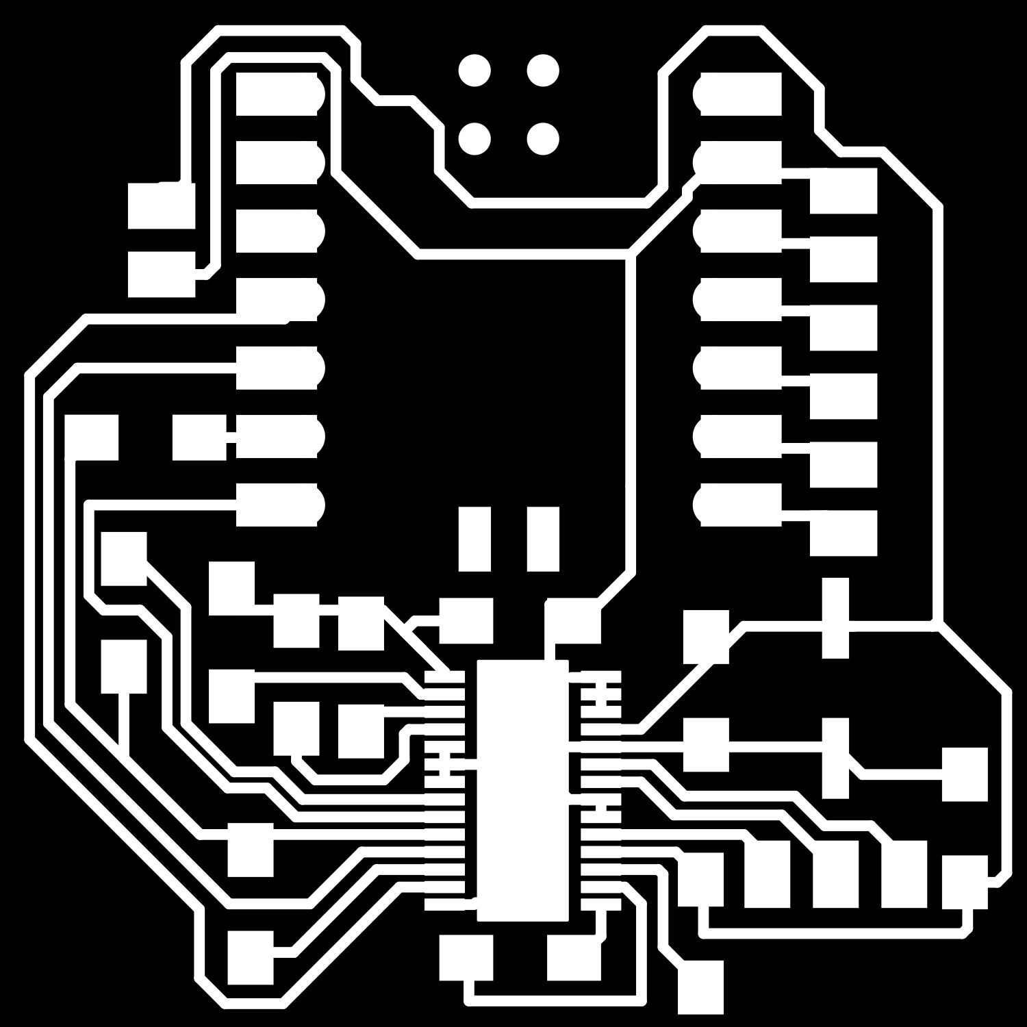
 PCB layout.
 |
 |
|---|---|
| PNG files for Mods CE. |
Assembly
Take care to connect the SPI cable to the angle sensor so that the wire colors are like this (the colors are not in the same order at both ends of the cable):

The SPI and motor wire connectors from the gimbal motor manufacturer are to small for the standard Fab Lab pin headers on our board. You need to crimp new female 2.54 pin headers onto the six SPI wires and the three motor wires (see the image at the top of this page).
The end of the SPI wires that connects to the BLDC board is like this:
white, pin 13, GND
red, pin 11, VDD3.3V
yellow, pin 4, MOSI
green, pin 3, MISO
blue, pin 2, CLK
black, pin 1, CSn
Programming
I tried to connect the board to Modular-Things, but I ran into trouble with the format of the string that I was trying to send to the microcontroller. It's just my inexperience with C++ datatypes.
How to use
- Install the SimpleFOC library.
- Connect the board.
- First test the sensor with this Arduino sketch and open the serial terminal to see the motor's position.
- Then upload the FOC motor control Arduino sketch to the board.
- Open a serial terminal, see a message that the motor has been initialized correctly and send a position command to the board.
The code accepts serial commands in the form
T3.14, where T means Target and 3.14 is the position in radians.
Todo
Connecting this board to the modular-things web interface is still in progress.