
Early depiction of pasta press, c1615, Image: Museo Giovanni Fabbri
A 3D printing process in which a material is forced thru a nozzle to create a bead, which is then laid down often but not always layer-by-layer to build a 3D shape.
The constitutive ideas of extruding raw materials thru an orifice to form a bead, and laying beads of material atop each other to create forms, are not new. For example:
Early depiction of pasta press, c1615, Image: Museo Giovanni Fabbri
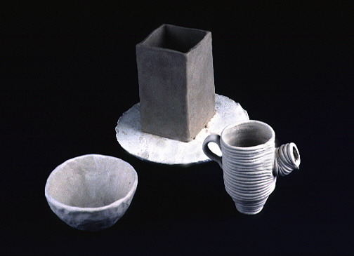
Coiled Ceramic Pots, c2500 BCE, Image: Smith College
Material extrusion 3D printing is an automated form of existing practices, where both the extrusion process as well as the position of the nozzle relative to the built form are under the control of a computer.
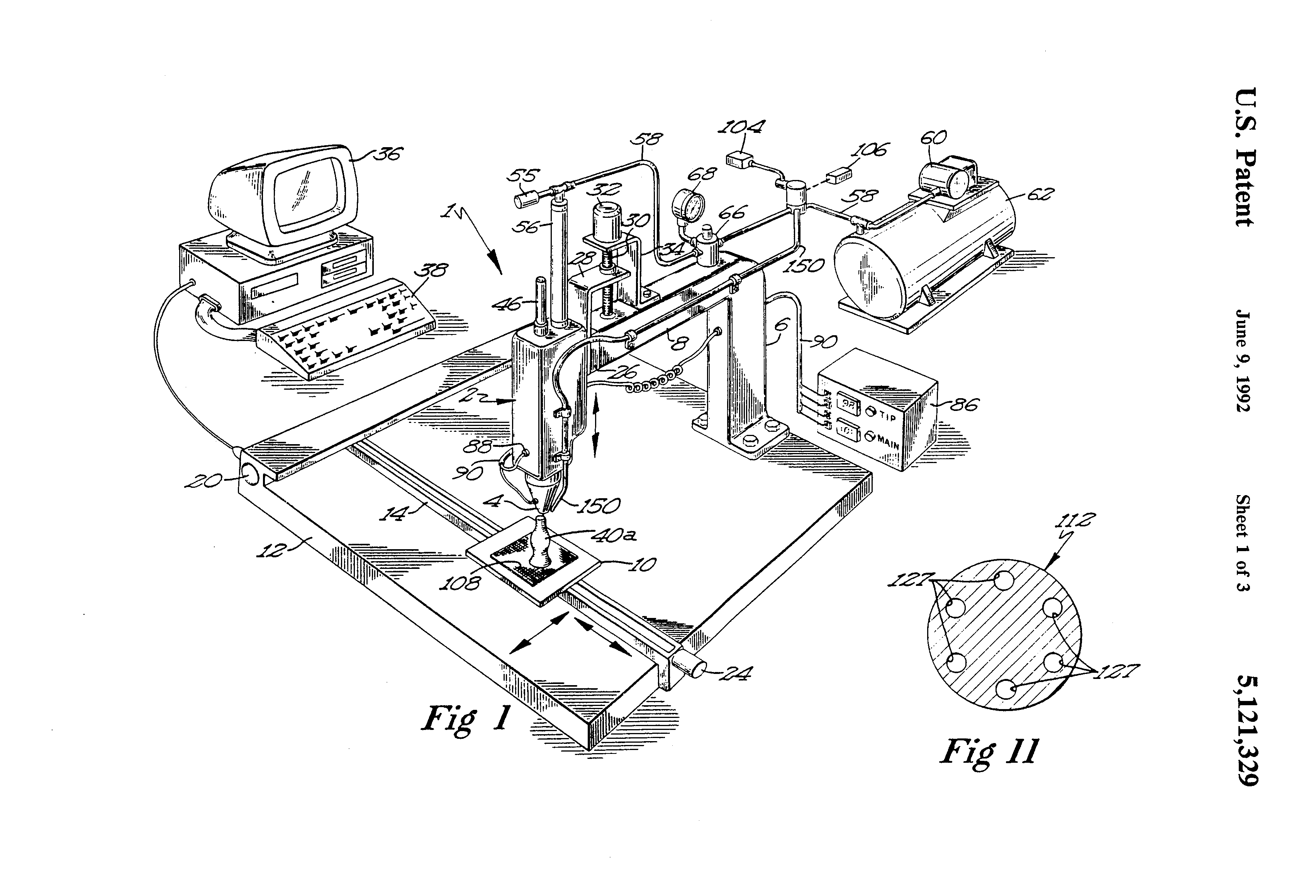
"...neither the wax-molding gun nor the known glue guns have ever been adapted or utilized in conjunction with mechanical means through which the dispensing gun and/or a substrate may be mechanically moved with respect to each other so as to generate a predetermined, three-dimensional shape by applying successive layers of material in a predetermined pattern"
in "Apparatus and Method for Creating Three-Dimensional Objects", US Patent #5,121,329 by Scott Crump (1989 Priority Date)
Under the broad umbrella of material extrusion, there are several meaningfully distinct processes that we will discuss:
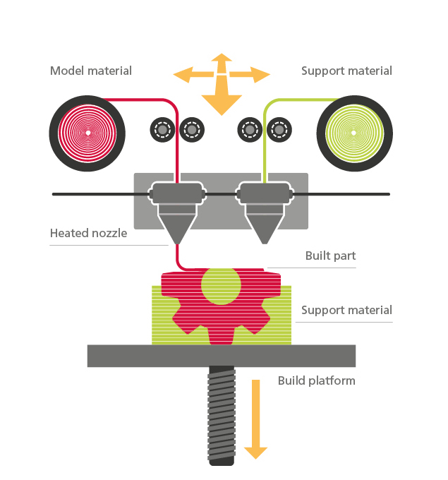
Image: Ricoh
Filament extrusion has arguably been the most important 3D printing technology from a cultural perspective, so we'll take a bit of time to discuss the history.
FDM was invented in 1989 by Scott Crump, founder of Stratasys. As the story goes, Crump came up with the idea while using a glue gun to make a toy frog for his daughter.

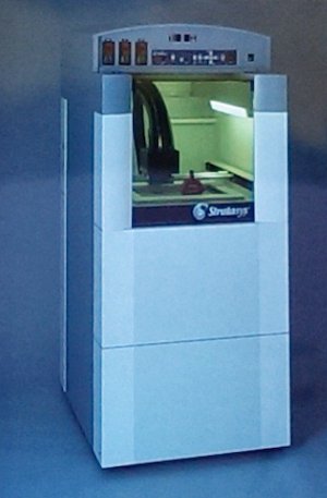
First Stratasys "3D Plotter", 1991 (Image from TCT Magazine)
It's worth noting the language used by Stratasys early on in the marketing of FDM technology; by calling it a "3D Plotter," they were likely trying to establish a mental model for a customer base whom could still relate to the 2D plotters used in engineering drafting. The XY positioning mechanism also looked quite a bit like a plotter.
In 1992 Stratasys began selling $200,000 3D printers, and thru patent protection had cornered the market for filament extrusion. The 1989 priority date is important because its expiration in 2009 triggered a Cambrian explosion of not only "hobby-grade" 3D printers, but also innovation and cultural awareness.
Stratasys "3D Modeler," 1992 (Image: TCT Magazine)
In 2004, Adrian Bower initiated the RepRap Project at the University of Bath, England, with the goal of creating a self-replicating fabrication machine. This was achieved in 2008, when RepRap "Darwin" printed over 50% of its own components.
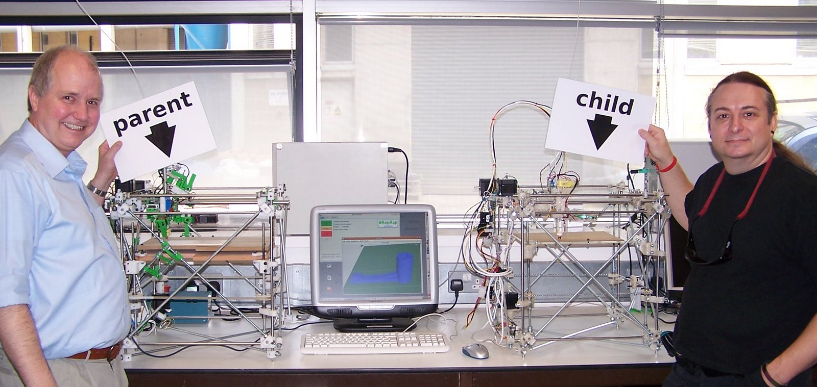
RepRap Darwin printing over 50% of its own parts. 2008. Image
Perhaps the most important initial contributions of the RepRap project were:
Soon after, in 2006, the Fab@Home project launched at Cornell, with a goal of enabling affordable, at-home 3D printing. While Fab@Home utilized a paste-based syringe extruder (discussed later), it also contributed to the ethos of accessible 3D printing for the masses thru open-source innovation. Relatedly to MAS.865, Max Lobovsky of Formlabs was an early team member of the Fab@Home project.
.jpg)
Fab@Home "Model 1" Multi-Material 3D Printer. 2006. Image: Hod Lipson.jpg)
While the Fab@Home project ended in 2012, RepRap continues to be a flourishing community. One new project is the μRepRap, which aims to "be a RepRap capable of micron (1/1000th of a millimetre, or 1µm) and sub-micron fabrication."
![[microreprap.jpg.webp]] μRepRap by Vic Olliver, 2024. Image: Hackaday
A few interesting datapoints indicating a zeitgeist:
This is pure speculation, but perhaps:
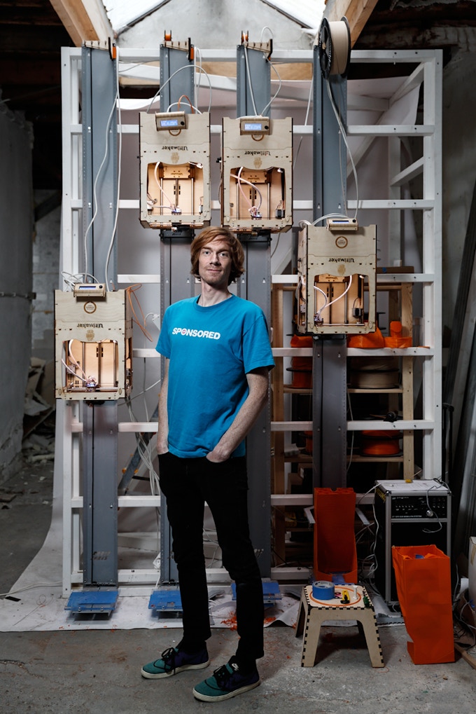
The RepRap project lead directly to the commercialization of hobbyist 3D printers, via RepRap contributors Zach "Hoeken" Smith (Makerbot) and Erik De Bruijn (Ultimaker). Note that the timing – 2009 – coincided with the expiration of the original Stratasys FDM patent.
Both companies sold their first machines as kits, for their end-users to assemble themselves.
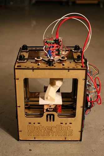
Makerbot Cupcake, 2009, via Thingiverse
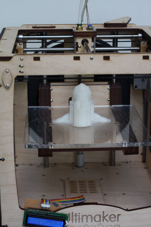
Ultimaker, 2010. (via Wayback Machine)
Relevant to MAS.865, Ultimaker was developed at FabLab Utrecht, and their low-inertia positioning mechanism was inspired by work done in HTMSTM(a)A 2009 (which in turn was inspired by the work of Greg Schroll in MIT course 2.12). According to the Ultimaker Blog from 2010, this mechanism enabled them to print at 150mm/s vs the then-standard 33mm/s when printing in then-popular ABS.
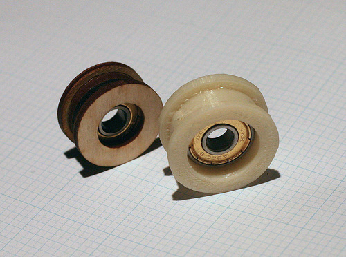
Makerbot Cupcake Idler Pulleys, 2009, via Wayback Machine
At MakerBot, we have a problem of production. You see, our CupCake CNC is made of a variety of components: electronics, lasercut parts, machined parts, and printed parts. To be specific, there are 4 idler pulleys that are printed _by_ the machine, _for_ the machine. Currently, we produce all of the idler pulleys on our own bank of MakerBots in our Brooklyn factory. This worked smoothly when we were shipping 20 bots a month. Lately, demand is increasing so fast that we’re ramping up production to be able to ship 50 to 100 bots a month. Our next production bottleneck is printing enough pulleys for the kits.  We could switch back to lasercut pulleys, but we’d rather not have to....

We will pay $1.00 / pulley for 608 Idler Pulleys. Download the linked file for the 608 Idler Pulley and print it out. When you have at least 30, mail them to us and we’ll either send you a check or pay you by Paypal.

One Euro-Per-Minute, Joris van Tubergen, 2011 (via Wayback Machine)
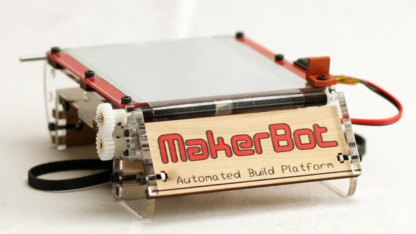
Automated Build Platform (part of the Makerbot Thing-O-Matic), 2010, via IEN

Battery-Powered Portable 3D Printing, Joris van Tubergen, 2011 (via Wayback Machine)
"Analog" heated build platform, also by Joris: https://www.youtube.com/watch?v=LktZsegiSIU
A heated build platforms help prevent warping of the first layers of a part as they cool, which I believe helps with dimensional stability of the part and improves adhesion of the first layers to the build platform. The Stratasys FDM machines solve this problem to an even greater extent with heated build chambers, but patent restrictions pushed the rest of the industry towards heated build platforms. This Stratasys patent expired in 2021.
Print speed in an FDM printer is limited by:

From "Fast Desktop-Scale Extrusion Additive Manufacturing," J. Go and A.J. Hart, Additive Manufacturing, Dec. 2017.
In the same paper, Go and Hart prototyped several improvements which, when combined, resulted in a measured improvements in volumetric flow rate of between 4.7 and 7 times over their benchmark Stratasys Mojo printer:
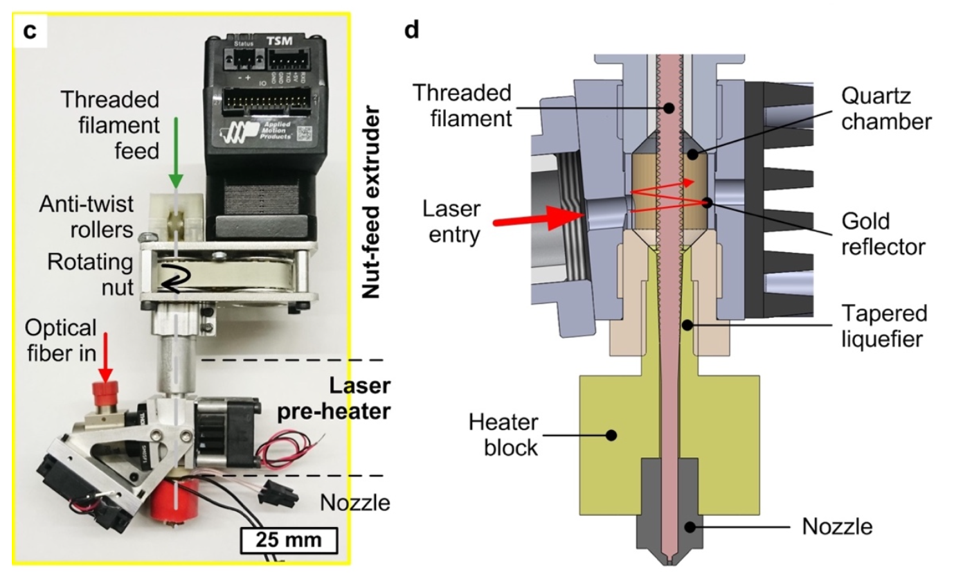
From "Fast Desktop-Scale Extrusion Additive Manufacturing," J. Go and A.J. Hart, Additive Manufacturing, Dec. 2017.
FDM 3D printers have moved away from serial kinematics towards parallel kinematics, where both motors are stationary, to reduce the moving mass of the system. Three of the most common low-inertia positioning systems are:
Another important innovation in reducing moving mass is the "Bowden tube" extruder:

A Bowden tube extruder on an "ultimaker-style" gantry. Image: Airwolf3D
The Bowden Tube is named after the "Bowden Mechanism," invented by Ernest Monnington Bowden in 1897, an exemplar of which is the break cables used on bicycles (and later aircraft control cables).
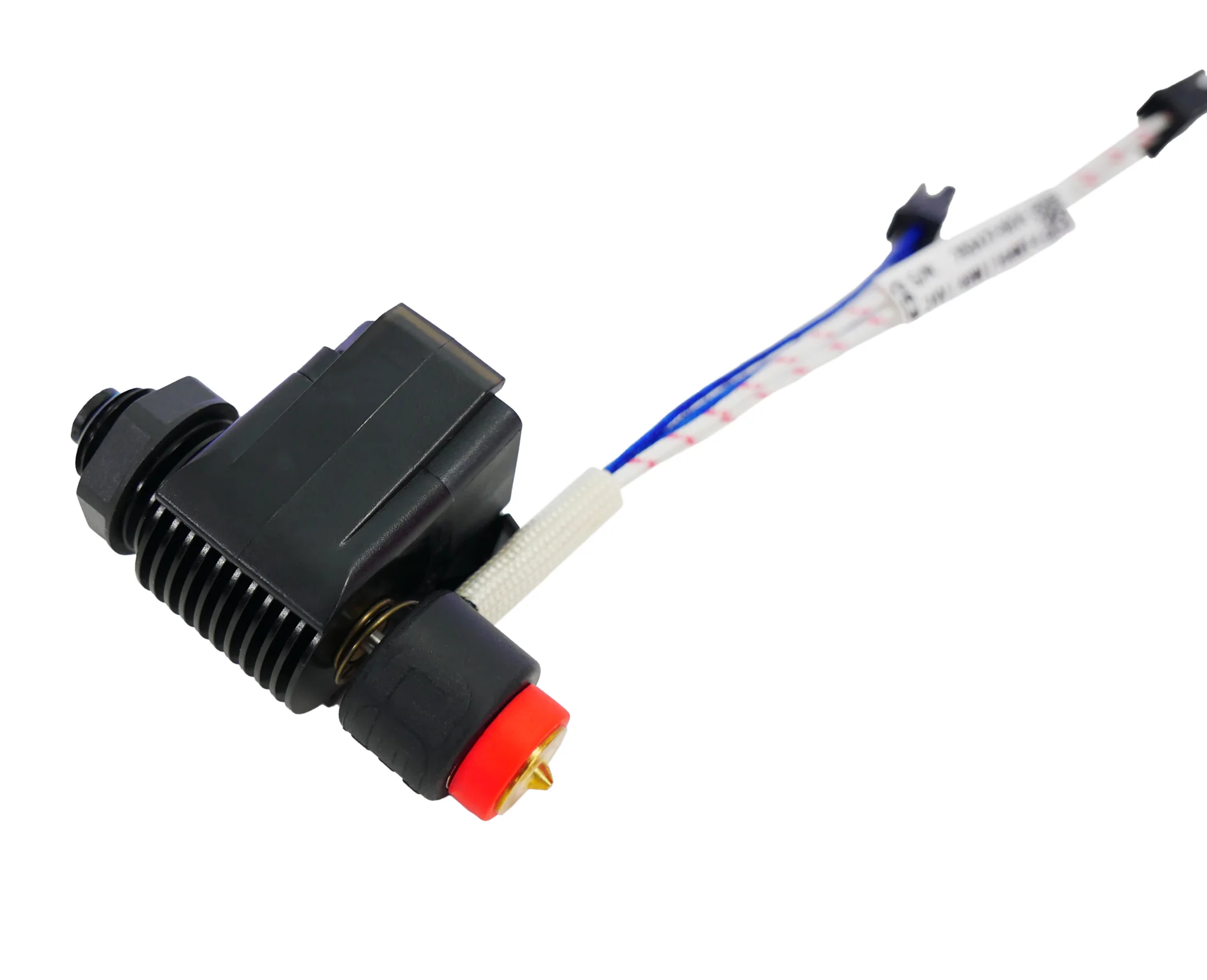
The E3D Revo Micro weighs only 30g. Source: E3D
While the advantage of the Bowden tube extruder is lower mass, its primary disadvantage is added mechanical compliance between the extruder and the nozzle, making precise dynamic control of extrusion rate more difficult.
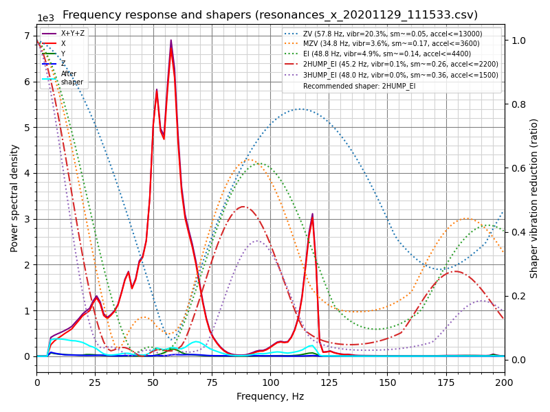
"Input Shaping" pre-processes motion trajectories and eliminates frequencies that might cause mechanical resonances. One example of this is the implementation in Klipper.
Before and After Input Shaping. Image from Joshua Vasquez / Hackaday.
Bambu Labs claims to implement "active vibration compensation":
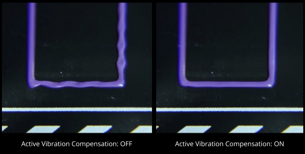
Source: Bambu Labs
Go and Hart describe a taxonomy of "small bead" and "large bead" 3D printers. The former purr and the latter roar; they define small bead as 0.1-1mm nozzle diameter, whereas large-bead is 1-10mm nozzle diameter.
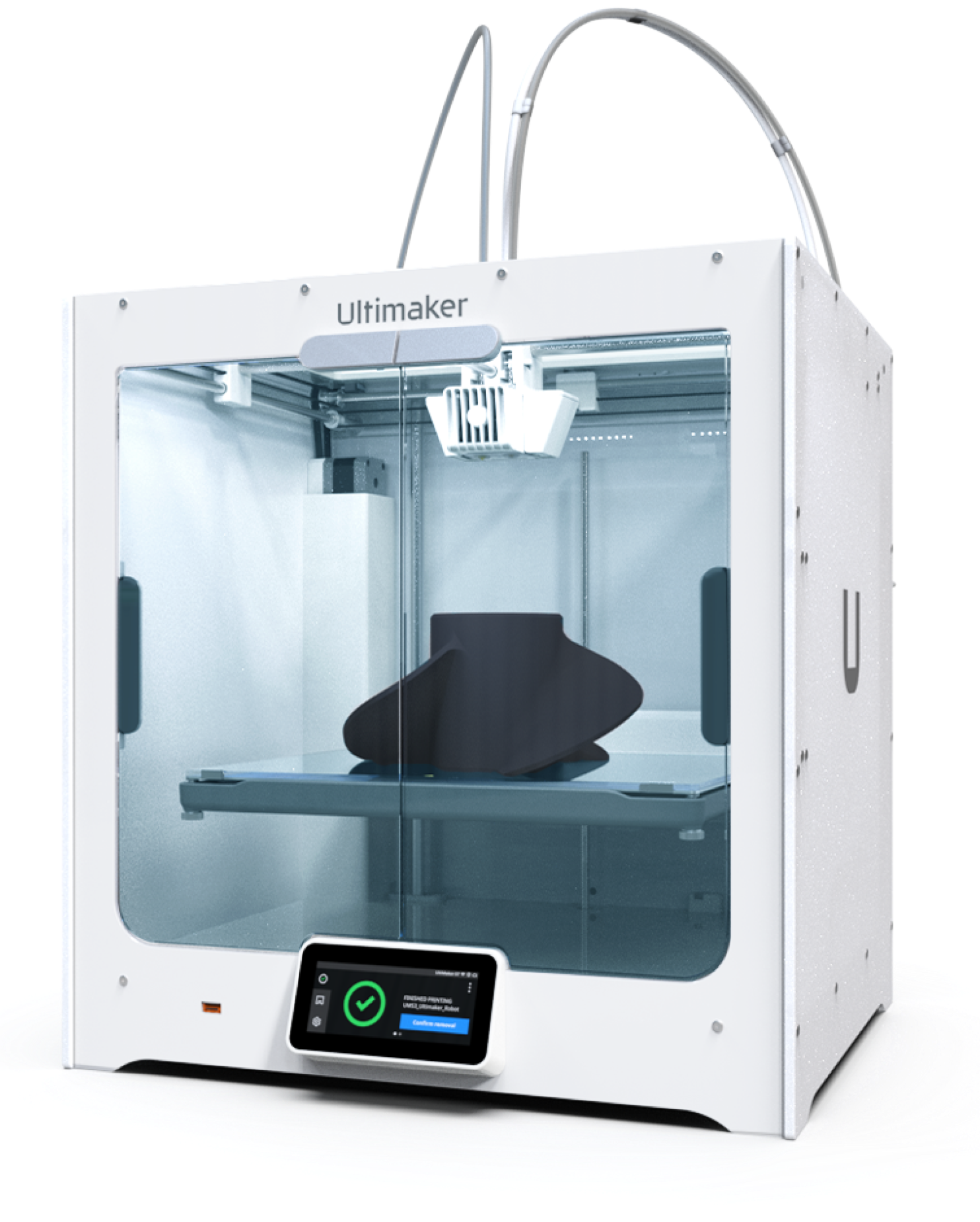
Source: Ultimaker
The below table summarizes the build volumes of several standard small-bead 3D printers currently on the market. For each, a build time to fill that volume has been calculated assuming a build rate of 20cm/hr and a 20% infill.
| Printer Name | Build Volume | cm^3 | Build Time* |
|---|---|---|---|
| Ultimaker S3 | 230 X 190 X 200 | 8.7k | 87 hr |
| Ultimaker S7 | 330 X 240 X 300 | 23.8k | 238 hr |
| Prusa i3 | 250 X 210 X 210 | 11.0k | 110 hr |
| Prusa XL | 360 X 360 X 360 | 46.7k | 467 hr |
| Bambu P1 | 256 X 256 X 256 | 16.8k | 168 hr |
The dynamic range of characteristic dimensions for these printers is only about 1.5:1, and the dynamic range of volume is 5.4:1. One limiting factor of build volume is likely the practicality of build time when utilizing that volume, due to volumetric flow rates.
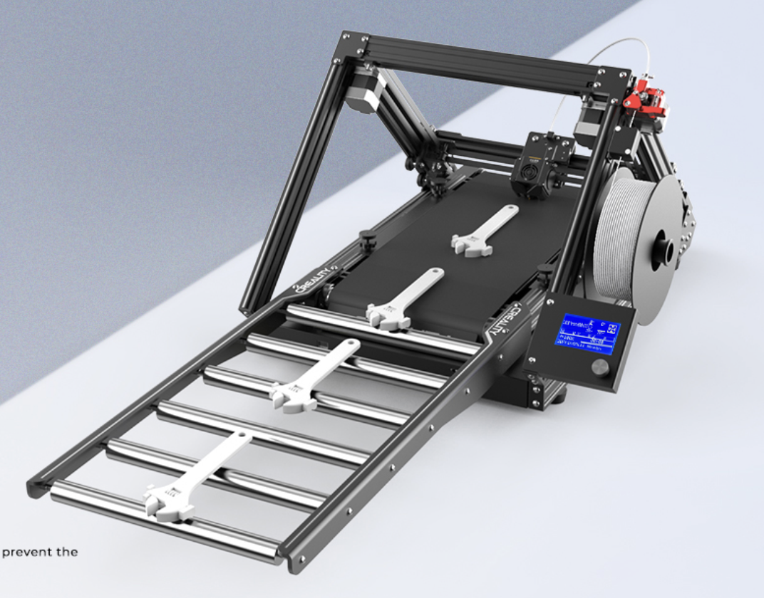
Creality 3DPrintMill "Infinite-Z" 3D Printer. Source: Creality
The "Infinite-Z" configuration places the motion plane of the printhead at an angle to a conveyor belt, which enables infinitely long parts to be printed, or a continuous series of parts as shown above.
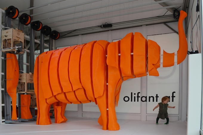
Another good example of large (but not quite infinite Z) is courtesy of Joris van Tubergen, for his exhibit at Schiphol Airport in Amsterdam:
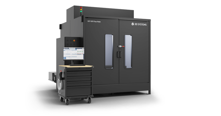
The 3D Systems EXT 1070 Pellet Printer. Source: 3D Systems
In contrast with small-bead printers, the 3D Systems EXT 1070 Pellet Printer has a print volume of approximately 1m x 1m x 1m (1M cm^3):
[Note: I'm confused by these numbers, because 3D systems also report filament extruder throughputs of 0.45-0.9kg/hr, which would be 450-900cm^3/hr. This is MUCH (>20x) higher than reported small-bead printers under presumably similar physics].
Source: 3D Systems
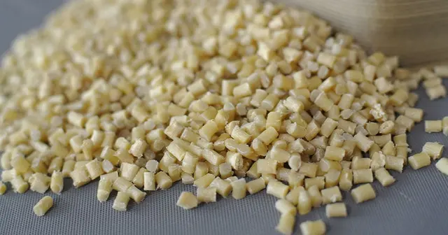
To support these high material flow rates, large-bead printers typically are fed by a pellet extruder. Plastic pellets are the standard industrial format of plastic used in injection molding, so material cost is much lower. As a datapoint, the commodity cost of PLA is currently $2.32/kg vs $25 for a spool of PLA filament from Hatchbox. [I'm not sure whether commodity costs include pelletization or not].
Pellets have the additional advantage that there are many more options in terms of off-the-shelf formulations, as well as compounding your own, adding colorants, etc...
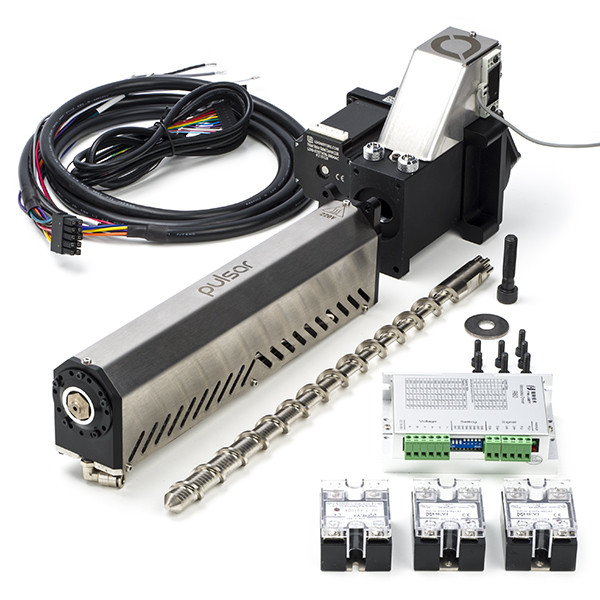
A pellet extruder from Dyze. Note the variable-depth screw, which increases compression as the pellets liquify. Source: 123-3D.
Another interesting large-bead 3D printer is the Big Area Additive Manufacturing (BAAM) machine, built by Cincinatti and Oak Ridge National Lab:
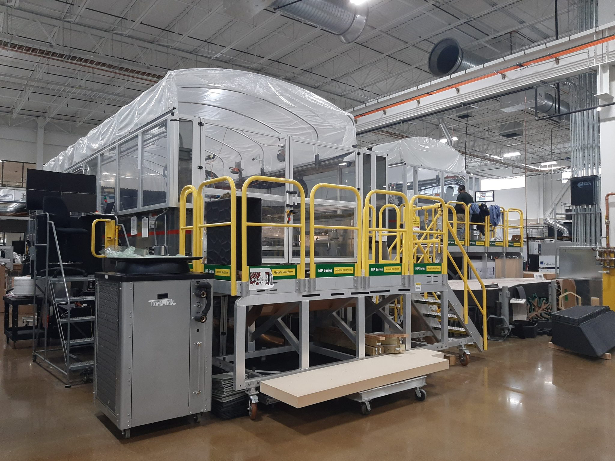
Cincinatti Big Area Additive Manufacturing. Image: Cincinatti, via 3D Printing Industry
The largest variant of the BAAM machine has a print volume of 6m x 2.25m x 1.8m, and weighs 20 tons. It can extrude 36k cm^3/hr (36kg/hr) with a nozzle diameter of 10mm [source]. For example, the following part weighs 200kg, is over 3m long, and took 7 hours to print:
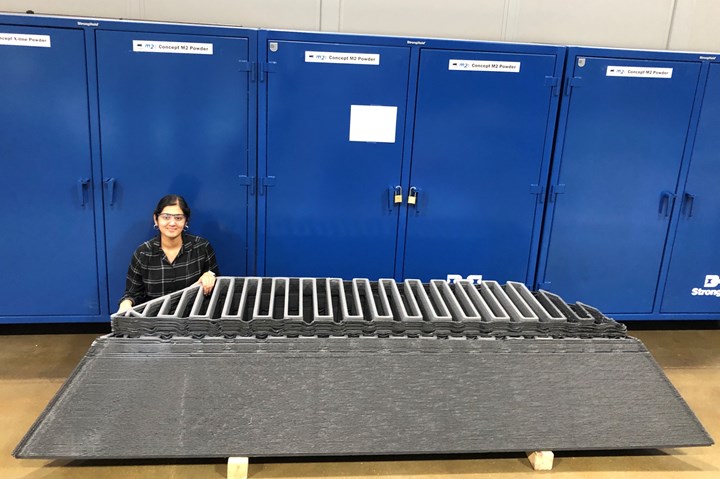
A multi-material precast-concrete tool produced on BAAM. Source: Composites World
One of the challenges of large-bead 3D printing is the tradeoff between speed and print accuracy. A clever solution to this is called "hybrid" 3D printing, where CNC milling is combined with 3D printing to achieve high volumetric throughput, while introducing accuracy just at the critical surfaces of the part. For example, the EXT 1070 supports two toolheads, which can be any of a large-bead pellet extruder, a small-bead filament extruder, and a milling spindle.

Early experiments at CBA with hybrid 3D printing + milling. Max Lobovsky and Ilan Moyer, 2010.
Feature size is driven by nozzle diameter. where 1xD is the smallest possible feature dimension in the XY plane Die swelling. Hydra Research has a good-looking (but I have not corroborated its accuracy) DFM website for FDM, where they recommend a minimum feature size of 4x the extrusion line width, or 1.8mm, whichever is greater.
Regarding positioning resolution, we can look at the Ultimaker S5 as an exemplar, which claims a positioning resolution of 7um in X and Y, and 2.5um in Z.
Layer height is an important resolution characteristic as well, as it dictates the minimum quanta of material deposition along the Z axis. The Ultimaker S5 claims layer heights as small as 20um, and dependent on the nozzle diameter:
| Nozzle Dia. | Min Layer Height | Max Layer Height |
|---|---|---|
| 0.25mm | 0.06mm | 0.15mm |
| 0.4mm | 0.02mm | 0.2mm |
| 0.6mm | 0.02mm | 0.3mm |
| 0.8mm | 0.02mm | 0.6mm |
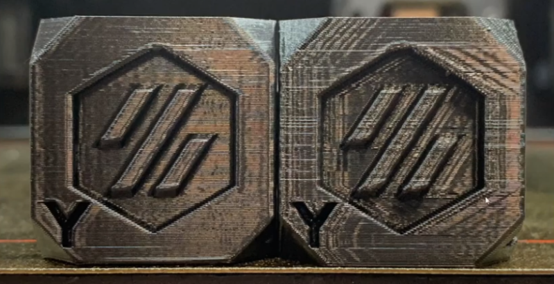
One clever trick is called "adaptive layer height," where the slicer dynamically adjusts the layer height based on the part geometry (e.g. the vertical slope of the part) to keep the surface smooth.
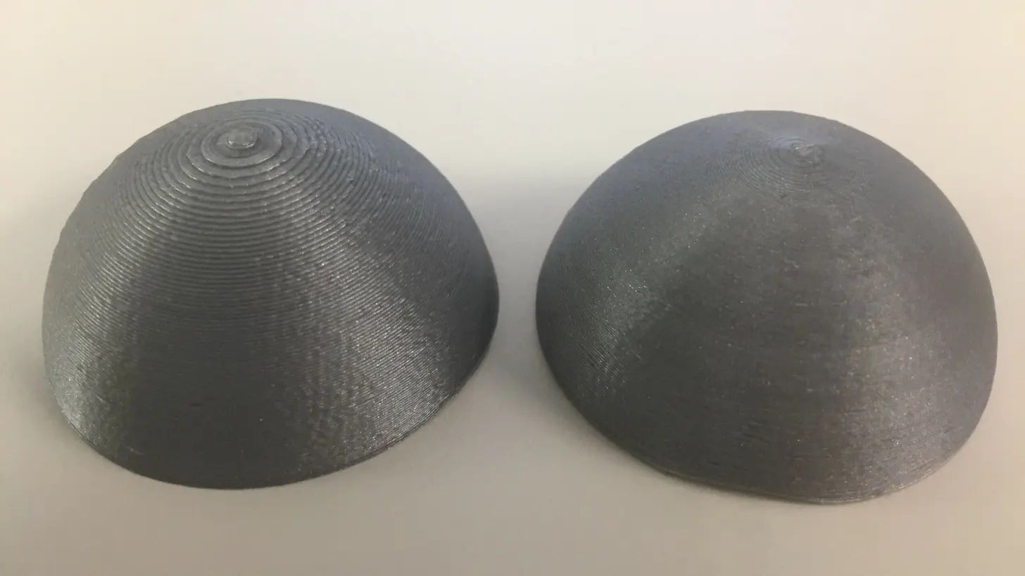
Constant layer height (left) exhibits more "stair-stepping" than adaptive layer height (right) where the slope of the part is shallow. Source: ChrisTerBeke via All3DP
Printing accuracy is likely a combined
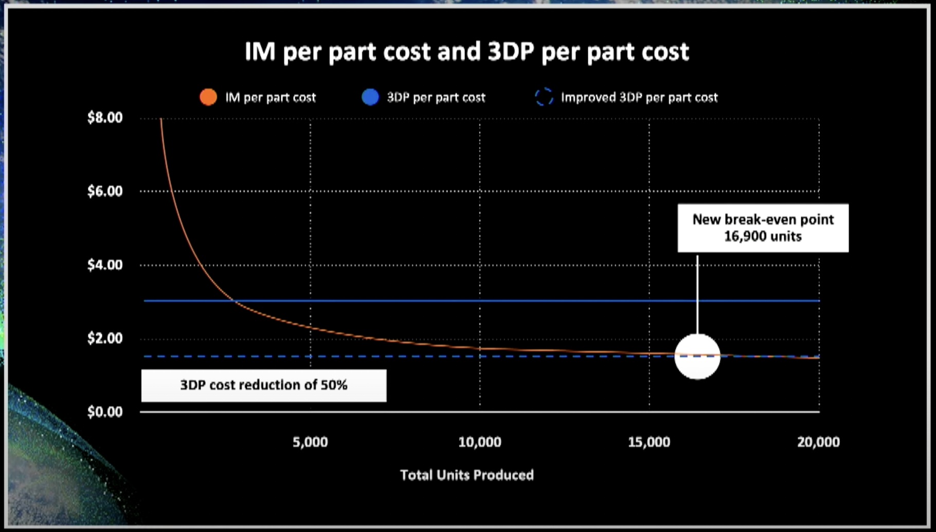
From Max Lobovsky's talk at The Digital Factory Conference, 2022
What's most interesting / exciting about this graph is the non-linearity towards the asymptote, where small differences in the cost of 3D printed parts have huge leverage on the break-even point with regards to other manufacturing methods.
filament production at home crowdsourcing heated build volumes heated build plates