- Usually, stepper motor windings are customized for an application. In other words, it is NOT normal to use off-the-shelf stepper motor designs in a mass-produced product.
- Given a ~fixed volume of copper, the tradeoff space is wire gauge vs number of windings → winding current, resistance, inductance, which affects how quickly the motor coils will charge and discharge, and average torque output at high speeds.
- Typical lead-times for prototype custom motors are 2-4wks.
- As you scale to production, you go from a prototype manufacturing line to [domestic manufacturing, depending on vendor] to overseas mfg at high volumes.
- In general, stepper motors are commodity items governed by fundamentals:
- How much copper you can fit in a given space
- Properties of electrical steel
- Strength of neodymium magnets
- HOWEVER, there is still innovation in stepper motor design, along dimensions such as:
- Lamination thickness
- Air gap
- ???
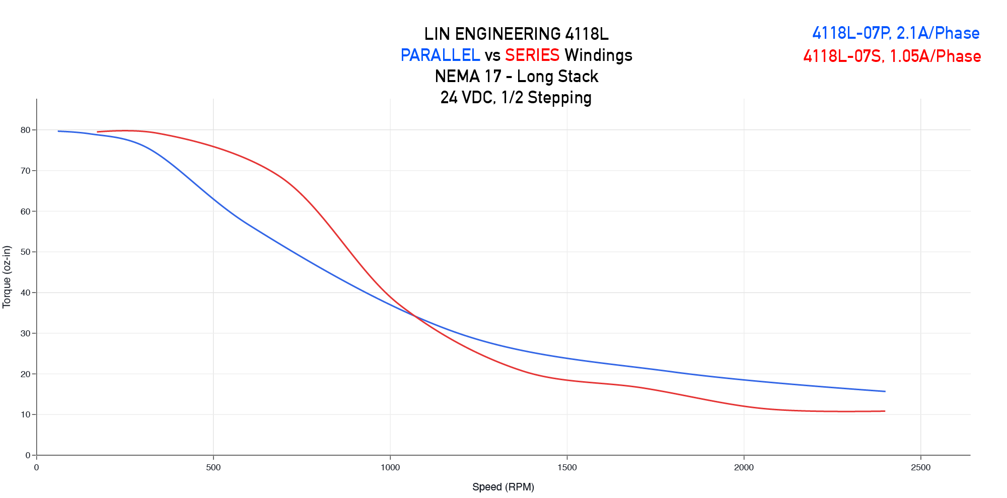
- These enable some motors that yield better performance in the same package size, eg Lin Engineering G4518 Series, 98ozf-in holding torque for G4518L, vs 83ozf-in for 4118L.
- Stepper Motor Manufacturers
- Motors are rated in amps/phase, which is an RMS value, such that the total power dissipated by the motor (sum of both phases) is constant at any point in the microstepping commutation table.
- Driver current is set as PEAK amps, which is ~1.4x amps RMS.
- A common mistake is to equate these two, and set your drive current too low.
- Caveat: if you park your motor at full-current in a position where only one phase is on, it can in theory overheat the winding, but in practice I haven’t seen indications of this being a real problem. Some drivers support lower current levels when stopped.
- Motor Mechanical Compliance
- The motors can represent a significant portion of the overall system compliance, especially in low-ratio (e.g. belt-driven) mechanisms.
- From Acarnley (p. 26):
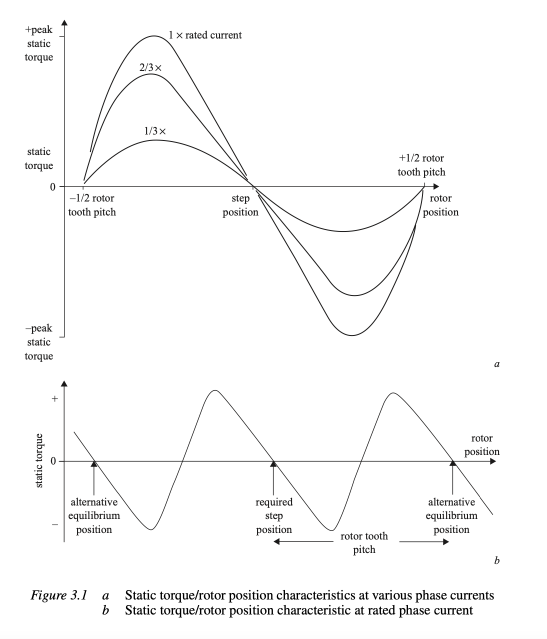
- Peak stiffness is when the electrical and mechanical positions of the motor are in phase.
- Maximum torque output occurs at +/- 1 step. Deflections exceeding 1 step result in “skipping steps” to the next equilibrium point, which is 4 steps away.
- This is the bible of stepper motors