Motors & Actuators
Last Revision: 2024.02.22
Dexter Callender & John Zhang
Notes for MAS.865 2024 HOW TO MAKE SOMETHING THAT MAKES (ALMOST) ANYTHING.
Below is a tentative outline of topics to be covered (more forthcoming).
- Electric machines
- Servomechanisms
- Solenoids
- Electrostatic actuators
- Piezo actuators
- Soft actuators
- Hydraulic actuators
- Pneumatic pistons
- Shape memory alloys
If you have a particular topic you are interested in seeing please email johnz@mit.edu
"the search for the perfect motor is neverending..." -- Charles Guan
Some Reading
Rolodex of blogs for motors
Relevant courses
Courses you can still take!
- 6.621 Electromagnetic Fields, Forces, and Motion
- 6.131/6.222 Power Electronics Lab
Courses no longer in existance:
- 6.238 Dynamics, Estimation, and Control of Electrical Machine Systems
- 6.685 Electric Machines
- 6.642 Continuum Electromechanics
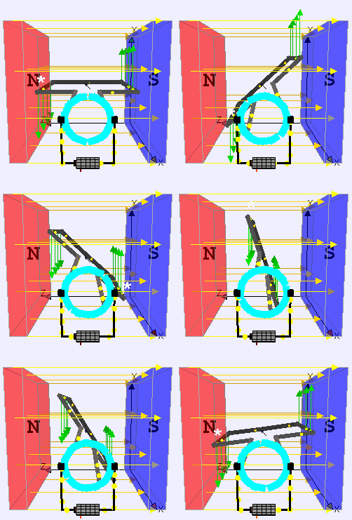
The Humble DC Brushed Motor

Image sourced from Wikipedia
DC Motor Model
The simplest model for a DC motor involves both the electrical and mechanical dynamics.
The electrical dynamics (ignoring inductance for simplicity, valid if the mechanical dynamics are slow compared to electrical dynamics) are $$ v - iR - v_\textrm{bemf} = 0 \tag{1}$$ and the mechanical dynamics are $$ (J_\textrm{motor} + \frac{J_\textrm{load}}{n^2})\ddot{\theta}_m + b\dot{\theta}_m + \frac{\tau}{n} = \tau_\textrm{motor}, \tag{2}$$ where the gear ratio $n$ relates the gearbox output shaft speed to the motor shaft speed $\dot{\theta} = \frac{\dot{\theta}_m}{n}$ and the output torque $\tau = n\tau_m$.
To close the loop, we need an equation relating the electrical and mechanical domains. The constitutive relations here are $$v_\textrm{bemf} = k_m \dot{\theta}_m \tag{3}$$ and $$\tau_\textrm{motor} = k_m i. \tag{4}$$
Now combining equations (1) and (3), we have
$$i = \frac{v}{R} - \frac{k_m\dot{\theta}_m}{R} \tag{5}$$
and equations (4) and (5) $$ \tau_\textrm{motor} = \frac{k_m}{R}v - \frac{k_m^2\dot{\theta}_m}{R}. \tag{6}$$
Finally, plug in (6) into (2) and group terms to find the equation governing the electromechanical dynamics
$$ (J_\textrm{motor} + \frac{J_\textrm{load}}{n^2})\ddot{\theta}_m + (b+\frac{k_m^2}{R})\dot{\theta}_m + \frac{\tau}{n} = \frac{k_m}{R}v \tag{7}.$$
Remarks:
- The bemf term acts like viscous damping.
- Note that the load inertia is divided by the gear ratio squared!
- Note that all other external loads accounted for by the external torque $\tau$, for instance gravity, is divided by the gear ratio.
- This model does not consider backlash, stiction, Coulomb friction, compliance, etc.
If we assume very little damping $b\rightarrow 0$ and take things in steady state for equation (7), we arrive at the famous motor torque-speed curve, $$\tau = \frac{nk_m}{R} v - \frac{(nk_m)^2}{R}\dot{\theta} \tag{8}$$
Aside: If you are using sensible SI units, then the torque/speed constant will have the same numerical value, which I will refer to as the motor constant $k_m$. Many hobby motor vendors will list the "Kv" of the motor, which has units of RPM per volt. It tells you the no load speed for a given voltage. More Kv means more speed for a given supply voltage. Values can range from 10s to 1000s of Kv. Lower Kv generally also means more torque for the same power. For a fixed stator and rotor design, the winding style (delta or star) and the number of windings will dictate the Kv or motor constant. More windings gives more torque (higher flux linkage), but at a lower speed (more bemf at a given speed).
So far we have considered only the lumped element abstraction of the motor. To see where $k_m$ comes from, let us analyze a single winding motor. The motor constant can be derived from the Lorentz force equation. Left as an exercise to the reader. It can be shown that $$k_m = 2 N B L R, \tag{9}$$ where $R$ is the radius of the motor armature, $L$ is roughly the length of your magnet/wire, $N$ is the number of wires, and $B$ is the magnetic field strength in Tesla.

Image sourced from https://uav.jreyn.net/quadcopter-design/step-5-motor-selection
Linear Actuation
Linear actuators can be motors in disguise! There are many ways to get linear motion using a motor. You can browse some of the mechanisms here. Here is a list of a few common examples to get started:
- Lead/ball screw actuators
- Cam mechanisms
- Gantries
More "true" linear actuators below.
Motor Sizing Examples
Motor Selection for a Pensa Labs Wire Bender
https://www.youtube.com/watch?v=pZ4cikp05o4
https://www.youtube.com/watch?v=kFG7AXqk6x4
Image sourced from: https://www.youtube.com/watch?v=_6B41IQNeJI
$$ T_\textrm{RMS} = \sqrt{ \frac{ (T_\textrm{1}^2 \cdot t_\textrm{1}) + (T_\textrm{2}^2 \cdot t_\textrm{2}^2) * (T_\textrm{n}^2 \cdot t_\textrm{n}) } { t_\textrm{total} } } $$
Motor Transplant for a Clausing Lathe
The MITERS Clausing has a new Prius motor inside after experiencing severe rotordynamic issues with the old drive.
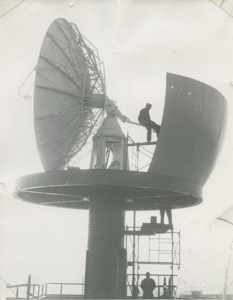
New Azimuth and Elevation Motors for the Radome
The Green Building Radome has a new set of BLDC motors to control the dish azimuth and elevation. These are replacing the original brushed 1/2-HP motors from the 1940's.

Analysis Example: Simple Solenoid using Energy Method
An electromagnetic solenoid a simple actuator that lends itself to analysis through the energy method. See for instance Kirtley's notes.
Useful also is Woodson & Melcher, Haus & Melcher, and CKKP.
Digression: Electrostatic Motors & Actuators
Electrostatic motors have been around since the time of Ben Franklin, but were relegated to the realm of parlor tricks or niche applications. It wasn't until the advent of MEMS that they found widespread use and commercial success.
C-Motive is attempting to commercialize macroscale electrostatic motor.
Stepper Motors
The modern stepper motor is god's gift to machine builders. Cheap, reliable, and open loop (see cheap & reliable). For many applications, it is the motor of choice. See for example every cheap (and some not so cheap) FDM 3D printer on the market.
Most steppers are two phase and are a hybrid synchronous (a combination of variable reluctance and permanent magnet).
Importantly, steppers move in discrete steps and can sustain a holding torque.

Image sourced from Wikipedia
Inside of a bipolar hybrid stepper motor:

Image sourced from Wikipedia
Microstepping and half stepping:

Image sourced from Wikipedia
CBA's favorite stepper motor + driver combo:
Stepper Motor Manufacturers (a partial list): Lin Engineering Koco Motion Nanotec
Servomechanisms
Servos are immensely useful actuators that bundle together a motor and a closed loop position control system. Perhaps most ubiquitous is the RC servo, which has tricked a generation of engineers into thinking they can plug a motor directly into an Arduino.
RC Servos
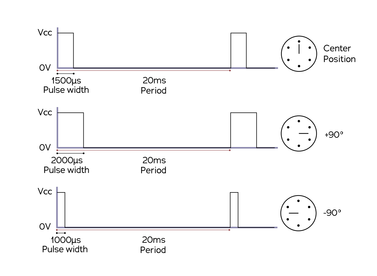
RC servos come in a nice package. You use WPM at 50 Hz (20 ms) to control them. They expect a pulse width between 1 ms to 2 ms. RC servos come in both continuous and position variety. If you have a high torque application consider splurging for a nice metal gear servo.


Dynamixels or Fancy Servos
Dynamixels are like RC servos, but fancy and expensive. They are continuous rotation, but have nice built-in controllers to do position or trajectory following.
T-Motor Type Actuators
A number of companies have popped up since Ben and Alex wrote their theses and made their motor actuator packages.
Piezo Actuators
Background
Piezoelectricity discovered by the brothers Curie in 1880. Now they're everywhere from the quartz in your watch, the pickup in your acoustic guitar, to the piezo inkjet actuators in your printer, to the igniter in your BBQ lighter, to even your bones (yes bone is slightly piezoelectric!).
The piezoelectric literature is confusing. Notation is all over the place and mechanical engineers and electrical engineers prefer different approaches to modeling piezos.

Piezoceramics
Piezoceramics like PZT can be used as high performance actuators.
Available to purchase as a piezostack from Thorlabs. There is also MIDE technologies located locally in Woburn Mass. A litany of cheap piezoelectric buzzers, motors, and pickups can be purchased on Amazon.
They produce extremely high forces for small displacements. Typical resonances are up in the 100's of kHz. You can treat it as a voltage sensitive force actuator. Combined with some drive circuitry and clever mechanisms you can do very fine positioning or produce other interesting behavior like stick-slip drives.
Piezofilm
Piezoelectric films are a more recent invention that have found use in more niche applications. Kawai in 1969 demonstrates that Polyvinylidene Flouride (PVDF) is piezoelectric. Measurement specialities has comprehensive guide on piezofilms.
Further reading
- MSI Document
- Tierstan's Piezoelectric Plates
- Preumont's Active Vibration Control
Hydraulic Actuation
Hydraulic actuation is both super old and super cool. The two most common examples are airplane control surfaces and large construction equipment. On the more "high tech" application side, Boston Dynamics is famous for their hydraulically actuated robot Atlas!
The engineers at BD have done amazing things with hydraulics. Custom printed plumbing and direct drive valves.
The control surfaces on an airplane are typically hydraulic with half of the systems running off one turbine and half of the other for redundancy.
Our friend the Clausing Lathe (from earlier) has hydraulic control for its variable speed control!

Although hydraulic actuators are high torque and power, they are challenging to control due to all of the parasitics. Ultimately, the control signal is still a motor driving a valve and the pump is powered by an BLDC so its motors all the way down. I've also been told that spiders are hydraulically actuated.
Thermal Actuation
A classic thermal actuator is the bimetallic strip in your oven. It works based on the different coefficients of thermal expansion of two bonded strips of metal. Conveniently, it also functions as the switch that controls the Joule heating or valve of your gas burner.
More sophisticated thermal actuators are shape memory alloys.
There are also highly specialized thermal actuators that are used for very precise applications.
Electro Active Polymers
Soft Actuators
Soft actuation has limited use especially if substantial power transfer or bandwidth is needed. There have been a number of fun examples in recent years.
Dynamometers
In the Netherlands, they'll road side dyno you! Dynomometers let you measure motor performance curves, e.g., efficiency at different operating points. Modern dynos typically will use an electric motor as the active load and measure speed with a tachometer and torque with a dynamic torque sensor (strain gauge + slip ring) to calculate shaft power.
Potpourri
- Planar Motors
- Engines?
- IPMs
- Induction Motors
- Voice Coils
- Piezoelectric fan
- World's fastest motor! ETHZ
- Heavy press program
- Handed shear auxetic actuators
- Edgerton's boomer
Some cool biological actuators:
- Spiders
- Frog legs
- Flagella bacteria
- Venus fly trap
- Muscle


