# Additive Path Planning
Additive Manufacturing or 3D printing is one kind of rapid prototyping technology. It is the process of joining materials layer upon layer to make objects based on 3D models. Additive toolpathing is simpler than subtractive because the problem is reduced from 3D to 2D.
The workflow typically follows these steps:
1. Loading model and preprocessing the model: *verifying that the input geometry meets fabrication requirements, determining the optimal orientation for building, assessing need for build structures.*
2. Slicing to obtain boundaries.
3. Dividing slices into various components: *planar vs nonplanar, constant vs adaptive*
4. Planning path.
5. Generating control code: *vector vs raster*
<p align="center">
<img src=img/add_workflow.png />
</p>
[Zhao and Guo](https://asmedigitalcollection.asme.org/manufacturingscience/article/142/1/010801/1046939/Shape-and-Performance-Controlled-Advanced-Design) Procedures of 3D slicing and path planning
Heuristics
* Build time
* Surface finish
* Material consumption
## Geometry requirements
Determining whether or not a 3D printer can print a geometry is a complex decision which depends heavily on the local thickness of an input geometry. If certain areas of the input mesh are too thin, they must with offset or thickened.
The limitations of which 3D-printed parts AM can produce includes: size, element thickness, how watertight it is (manifold) and curved surfaces.
### Printer Size
The size of the part a 3D printer can create will differ depending on the printer you're using to manufacture parts. Recommendations include using an industrial printer for more sizable parts and splitting parts into 2 or more components to be printed separately and assembled after.
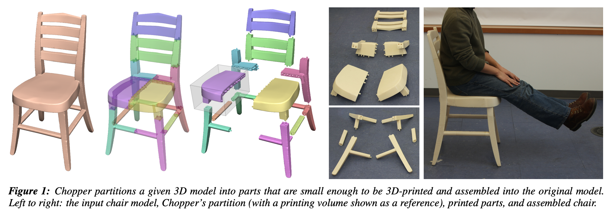
[Luo, et. al](https://gfx.cs.princeton.edu/pubs/Luo_2012_CPM/chopper.pdf) proposes a framework called the "Chopper" which can decompose large 3D objects into smaller parts to fit into a given printing volume. The Chopper can automatically (or with user guidance) optimize parts for ease of assembly, minimal part count, structural soundness, and unobtrusive seams.
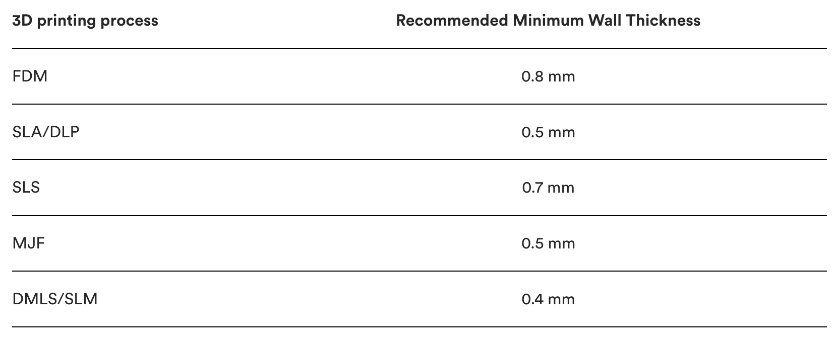
### Minimum Wall Thickness
Another major factor to keep in mind when designing a part for 3D printing is the thickness of all the walls. Every 3D printing process has a standard minimum wall thickness (or at least a highly recommended one).
In general, it’s impossible to print very thin features unless they are wider than the minimum printable feature size for a given additive process.
Here are the recommended minimum wall thickness from [Protolabs](https://www.hubs.com/knowledge-base/3d-printing-geometry-restrictions/) for the most common 3D printing technologies. Note that in some cases, like SLA, it’s possible to print smaller features, but this should be assessed on a case-by-case basis.
### Why should a 3D model be manifold or watertight?
Every 3D model intended for 3D printing should be completely manifold (aka watertight), meaning that every edge should be connected to exactly 2 polygons and the model must include no holes (unless they’re integral to the design).
Models that are not manifold might get misinterpreted by the software that generates the instructions for the 3D printer (slicer). A non-manifold 3D model might cause the print itself to have inconsistent layers, holes or other errors. This will render your desired object very likely unprintable.
Every model is built out of polygons, which are also called faces. Every sigle polygon is the surface between 3 or 4 edges, and every one of these edges needs to have 2 polygons connected to either side of it.
Non-manifold issues are often not visible at the modeling stage. The simplest way to check whether a model is printable is to use an analyzer software. These programs detect model features that will cause issues at the 3D printing stage and offer repair options (without impacting the overall geometry of the model).
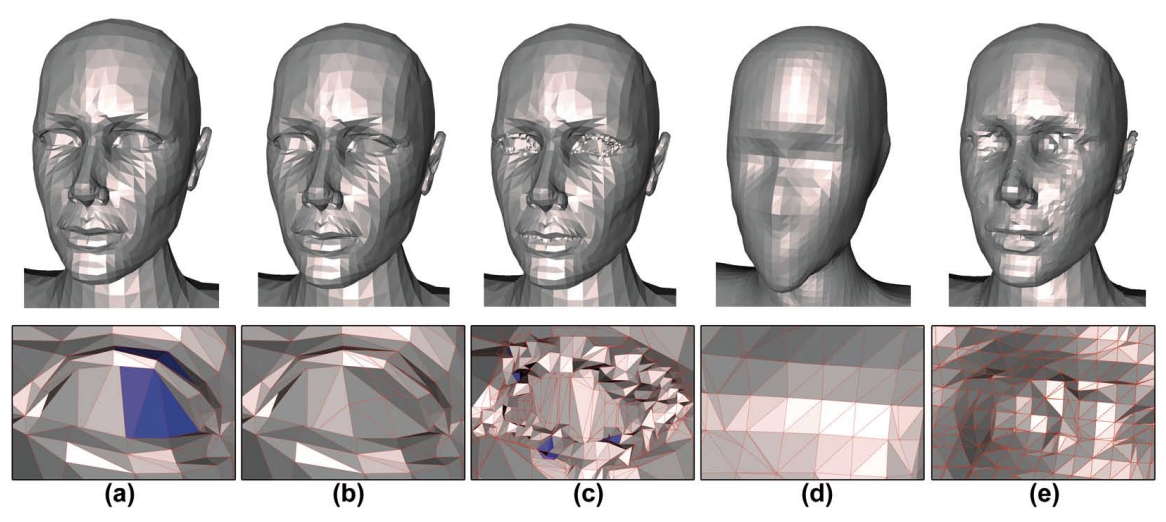
A list of [open source mesh repair resources](https://meshrepair.org/). It can also be useful to reduce the complexity of meshes by decimating triangulated surfaces while preserving geometric detail or resampling meshes to increase the number of triangles. For example, 3D scanned models can output messy meshes that can have overlapping parts, surface holes, and/or self-intersections.
[A lightweight approach to repairing digitized polygon meshes](http://saturno.ge.imati.cnr.it/ima/personal/attene/PersonalPage/pdf/TVC2010_preprint.pdf) is the founding paper around simple, localized mesh repair.
## Slicing
Once an adequate mesh is created, the structure is sliced from a volume to a plane. The slicer must determine:
- vertical position of each slice
- efficiently compute the contour within each slice
- fill the contour with a toolpath
Types of slicing
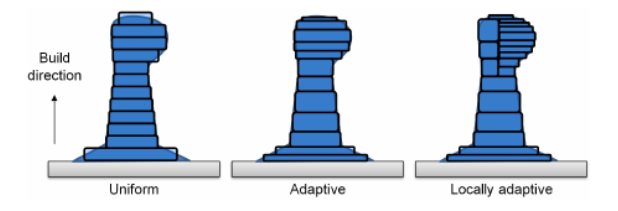
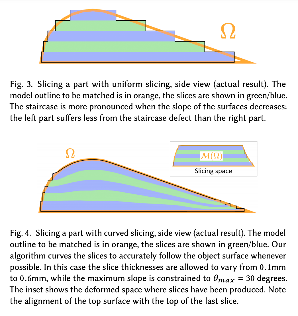
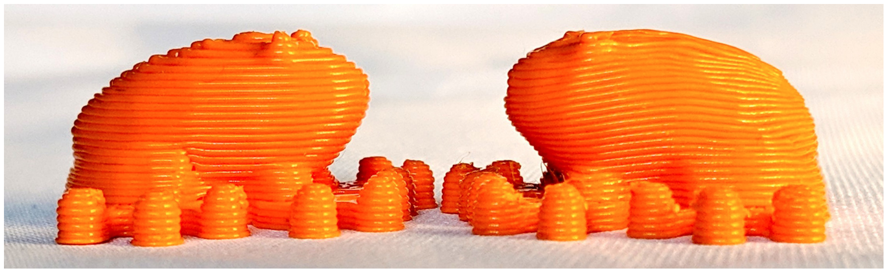
1. **Uniform slicing**: uniform slice distance across the whole object. effective for objects with vertical walls but results in surface errors called the *staircase effect*.
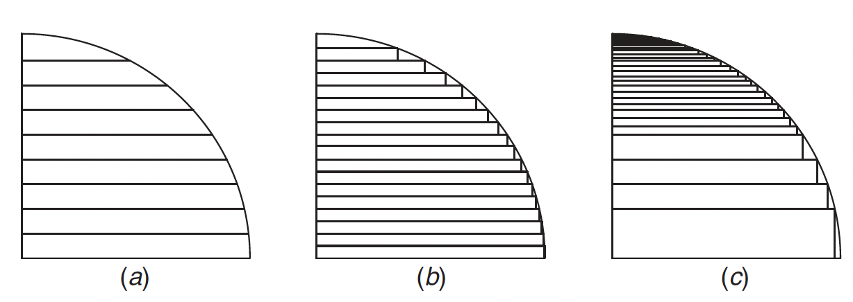
[Effect of layer thickness on surface smoothness](https://asmedigitalcollection.asme.org/manufacturingscience/article/142/1/010801/1046939/Shape-and-Performance-Controlled-Advanced-Design): (a) thick layer, (b) thin layer, and (c) variable layer
2. **Adaptive slicing**: modifies layer thickness based on the curvature of the volume at that height. Local adaptive slicing changes the layer height only on sections of the object that require it, though this can create seams along the solid.
unidirectional and multidirectional
curved layer (uniform and adaptive)
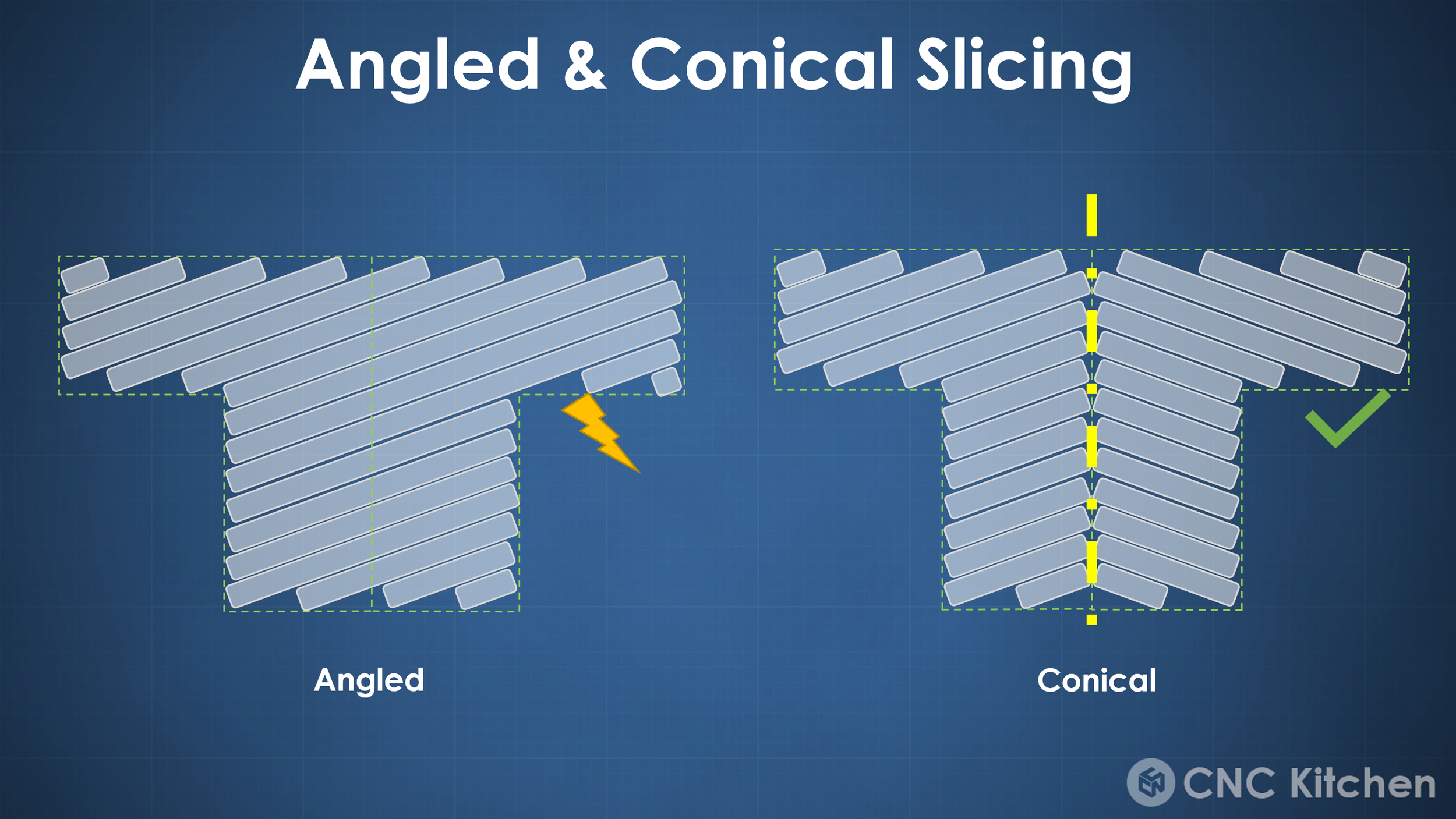
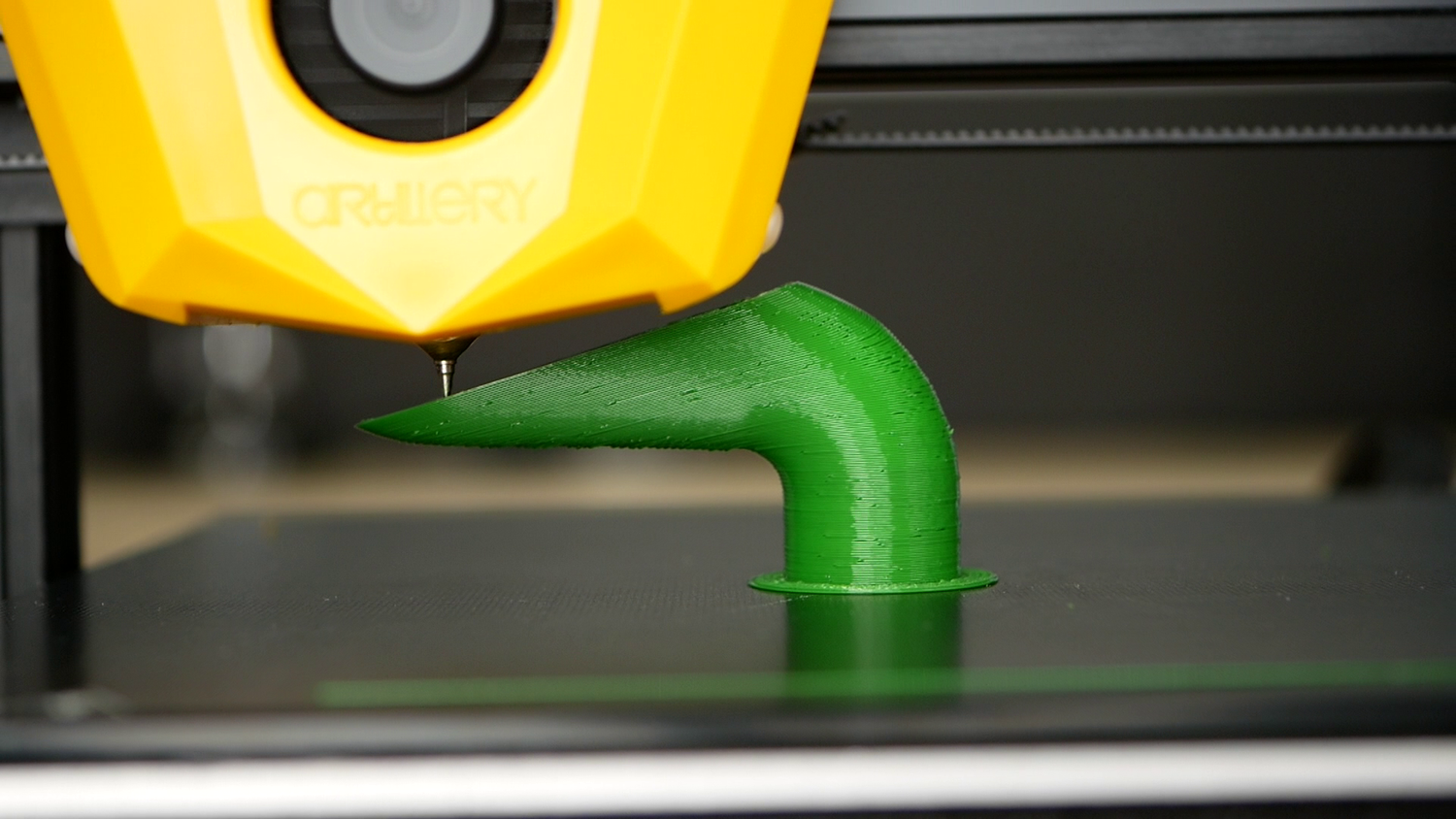
3. [Conical Slicing](https://www.cnckitchen.com/blog/conical-slicing-a-different-angle-of-3d-printing): non-planar, conical slicing for supportless prints. Common FDM 3D printers are able to print angles < 10-15°. Here, layers are tilted a tiny bit so that even when printing horizontal overhangs, only maybe the outermost perimeter is printed in mid-air, yet still sticks and is supported by the perimeter next to it. Here, printing layers are tilted around a central axis and therefore forms a cone.
4. **Curved Slicer**: At the expense of more complex computation, non-planar extrusion leads to better surface quality, optimized printing time, better self-support, and improved tensile strength. [CurviSlicer](https://hal.archives-ouvertes.fr/hal-02120033) bypasses computing curved layers directly by first transforming the model to be more flat, slice the object with the standard planar approach, then recovering the object's initial curvature
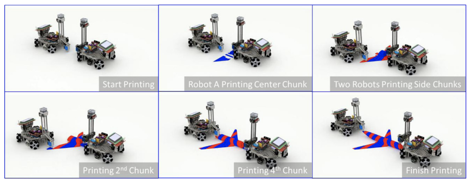
5. **Collaborative**: [Chunk-based slicing](https://www.emerald.com/insight/content/doi/10.1108/RPJ-07-2017-0150/full/html) to divide print jobs into chunks so that different mobile printers can print different chunks simultaneously without interfering with each other.
## Support structures
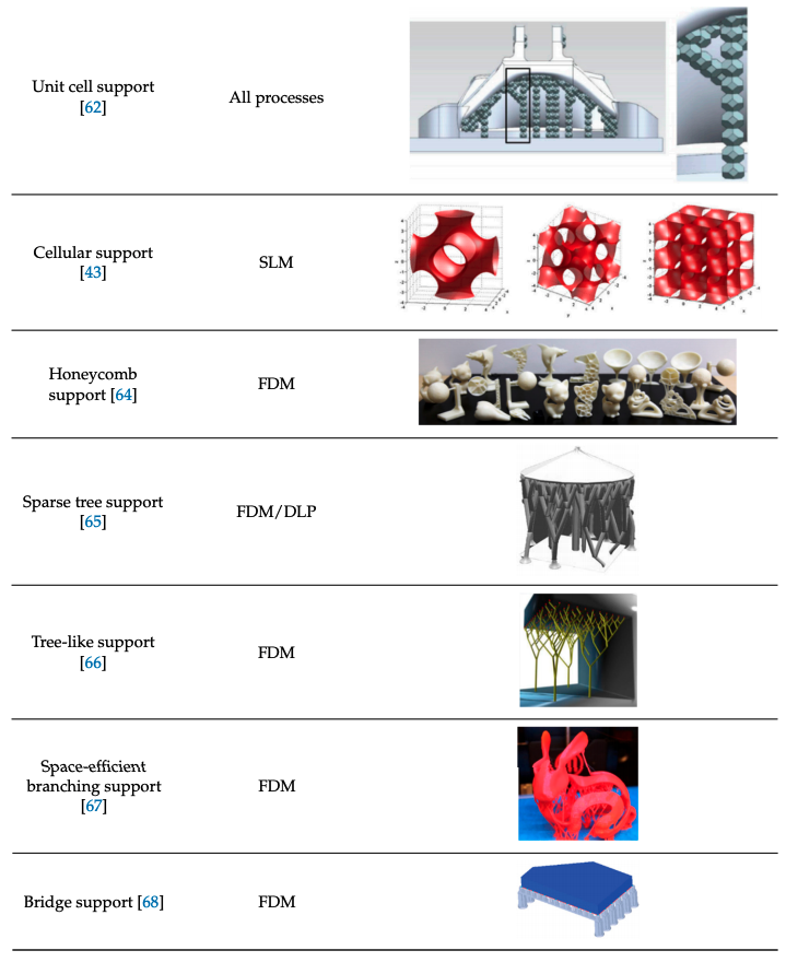
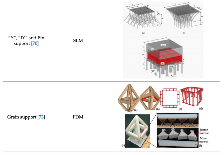
Support structures compensate for limitations due to gravity, structural strain, or thermal dissipation. Determining support placement is important to optimize due to the excess build time, material waste, and post processing that they introduce.
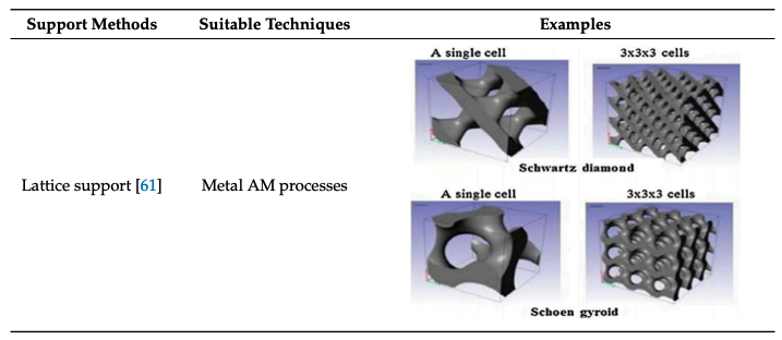
[Jiang et. al.'s 2018 review paper](https://www.mdpi.com/2504-4494/2/4/64/pdf) on support structures for additive manufacturing provides a clear comparison between different methods matched to process techniques.
### Support Free Printing
- SLS, MJF and binder jetting 3D printing never require support structures, so these are the preferred methods for more complex geometries.
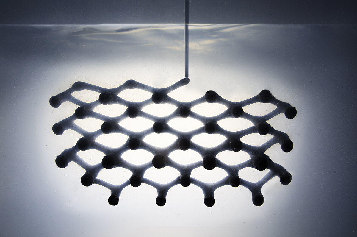
- [Rapid Liquid Printing](https://www.rapidliquidprint.co/), demonstrated by MIT Self Assembly Lab, which UV cures resin suspended in gel.
- [Near-infrared assisted direct ink writing](https://www.nature.com/articles/s41467-023-38082-8) for ceramic printing which combines DIW and photopolymerization. [video](https://youtu.be/3_5KAutsNaw?si=sa2Hq9sp2b5chMK3)
## Fast Additive Manufacturing
[Online Measurement for Parameter Discovery in
Fused Filament Fabrication](https://link.springer.com/article/10.1007/s40192-024-00350-w) Further complexity in FFF can be found outside of the extrusion process itself. As
we will see in this work, **flow can always be increased by increasing nozzle temperature,
but over-heating filament in the nozzle can lead to slumping of the printed part**. This
is simple to understand: once printed, the filament is unconstrained and if it is too
molten it will not hold its deposited shape. To compound this, the filament is typically
resting on a previous layer of filament, and so prints need to be strong enough, as
they are being printed, to remain self-supporting. This phenomenology has led to the
inclusion of ‘part cooling fans’ in most extruder designs that allow nozzle temperatures
to remain large while quickly cooling filament on exit to avoid slumping.
## Infill
The internal supports of a printed object has significant impact on build time, material use, and structural stability.
### Dense infill
Common infill patterns:
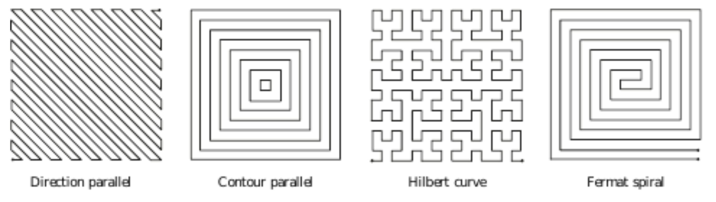
**Direction parallel**: (aka zig-zag) equally spaced parallel line segments. There are a lot of sharp corners in this fill, which makes complex shapes or hollow structures difficult and adds unnecessary de-acceleration and acceleration times for an extruder toolhead.
**Contour parallel**: paths are defined by iso-contours of the euclidean distance transform. However, contours are disconnected from each other, which can lead to difficult gaps. Sometimes a mix of a few contour curves and then zig-zag fills will be used.
**Hilbert curve**: is a space filling curve which is designed to wind and bend itself to preserve locality as it travels through a space. This is a classic space filling curve used in some manufacturing, although it's not the best choice for infill because of the constant sharp turns that it's defined to take.
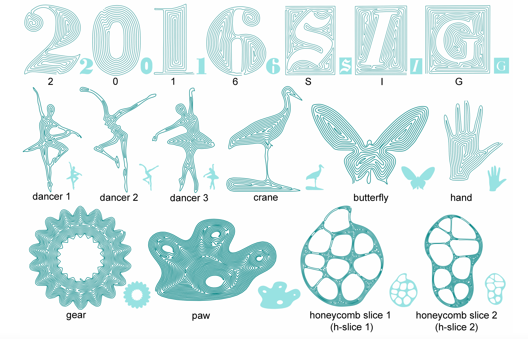
**Fermat Spirals**: are a type of space-filling curve that is designed to avoid bending - although it's not guaranteed to cover an entire 2D space, even at infinite resolution. They are also beneficial because they can have arbitrary start and end points and continuous connections, allowing a curve to spiral both in and out as opposed to one or the other. However, spirals can be suboptimal filling patterns due to their lack of direction bias, which prevents cross woven slices for mechanical uniformity. See [Zhao, et. al.](https://www.cs.sfu.ca/~haoz/pubs/zhao_sig16_fermat.pdf) for more on Fermat spirals shown below.
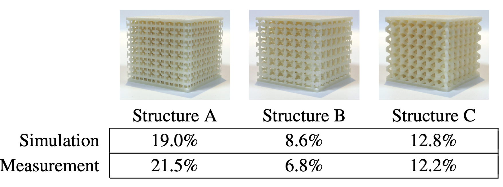
### Metamaterials
These can be optimized to use as little material as possible while maintaining structural strength. Furthermore, internal microstructures used to create metamaterials that have pre-defined control over elasticity, as demonstrated by [Schumacher et. al.](https://dl.acm.org/doi/pdf/10.1145/2766926)