1. Plasma Shaping
a. (Nozzle) Cathode/Anode shape
b. Corona Plasma discharging
i. 20 – 400
oC gas temperature
ii. Cooling Systems not so strict
iii. Access to Low Melting Point Materials
iv. Require high voltages
c. Plasma torch & Arc discharging
i. 3000
oC and greater gas temperatures
ii. Cooling System considerations
iii. Access to all Material systems
iv. Require high wattages
d. Solenoid Coils
e. Plasma Gas Choice
| Nitrogen | Hydrogen | Argon Helium |
|
|
|
 |
 |
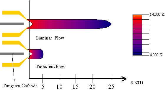
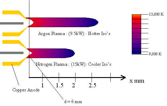
i. Plasma Gas Temperature
ii. Plasma distribution
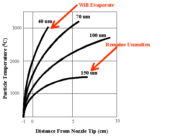
iii. Particle Velocities
2. Gas Shaping
a. Direct injected downstream flow
b. Secondary enshrouding flow
3. Material Particle Shaping
a. Plasma entry location
b. Solenoid Coils
c. Masking Hole
i. Hole diameter
ii. Low stiction coefficient material or coating
4. Cooling
a. Gas Cooling vs. water Cooling
b. Regime of operation of Plasma
c. Nozzle shape
d. Cathode & Anode Metal materials
5. Material Choice
 |
a. Organics
i. Low melting points
ii. Delivery Deformation distortion of properties
iii. Nitrogen flow to prevent oxidation
b. Inorganic Metal Powders
i. High melting points
ii. Nitrogen flow to prevent oxidation
6. Addressable
a. Horizontal Setup
b. Substrate Mounted Gantry
c. Powder Delivery
i. Gravity powered entry
ii. Pressurized Delivery
iii. Multi-Material automation injection


Design Parameters
- nozzle to substrate
- powder injector to plasma
- Mask to substrate
- Mask to Focused Material