With Scott Greenwald and Marcelo Coelho, I conceived the initial funnel + puncher design.

As we moved away from the Legos and continue with custom designed parts, I also focused on visually documenting the disucssions so that 1) we are all on the same page, and 2) we can communicate the concepts to other people.

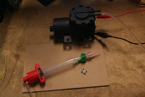
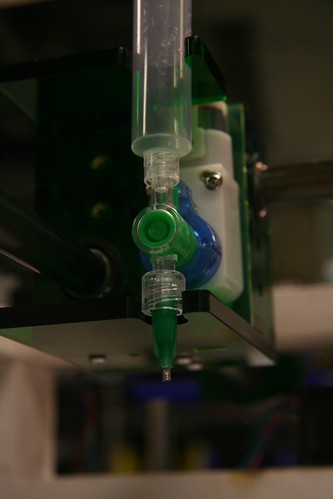
With the custom parts, I worked on the vacuum pickup scheme, first using the vacuum pen, and then next using a syringe with a vacuum engine.


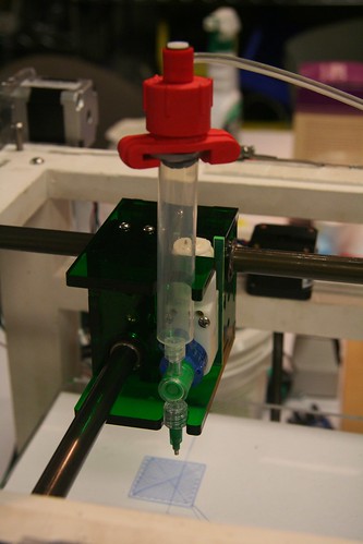
Personally, I was interested in making a GIK assembler using this vacuum pickup and the cam shaft Scott had already made. I also looked at Solder Gun as a way to integrating pressfit with vacuum pickup. I didn't get to make one though.


Since I hadn't taken HTMAA, I had to first learn the "fab way" of PCBing and programming... First I tried capacitive sensing with hello.step.45. Jonathan Ward guided me throughout, thank you!


Fun Sensing/Feedback exercise: On average Americans are exposed to 300,000 logos and brand impressions a day. Imagine a bottle whose branding and marketing label follows you, as you twist open the bottle...


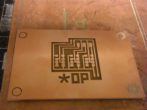
I started with the hello.light.45 board, but used two optical interruptors/Photomicrosensors (Transmissive) EE-SX1103 instead of the usual phototransistor.

Became messy pretty soon -- needed a bigger board with more traces.
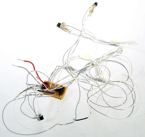
Next, I extended the board to accommodate 2 optical interruptors.

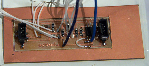

For the active elements (aka Starbot) team, I fabbed the optical encoder PCB which was integrated to the bot's main PCB. Worked with Skylar Tibbits, Ara Kranian, Forrest Green, Kenny Cheung, Taro Narahara and David Dalrymple.
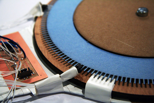
Kenny suggested reflective sensors, so I picked a photosensor QRE1113 and designed the Grey Code thanks to Adam Kumpf's help.


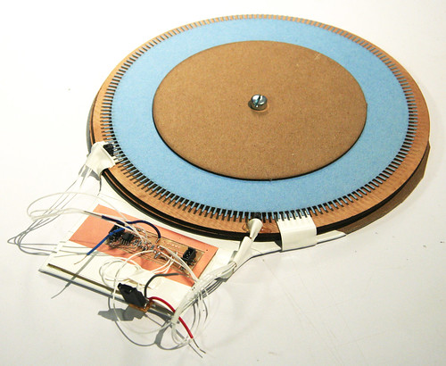
Taro and I milled out the PCB, and I tested the collector voltage with lasercut black and white stripes.
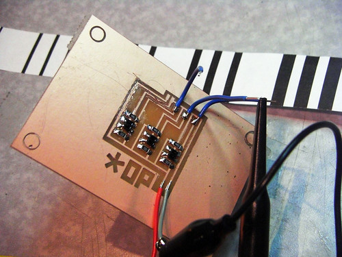
Ara and I mounted it on a Starbot and tested the signal out...

After the test, we up'ed the resistor from 49.9K to 100K and then I soldered total 8 of them.
