Phygital Assembly (Tangible CAD)
Digital Twin for Real-time Assembly Tracking and Physical Making. An integrated system synchronizing physical fabrication with a digital modeling environment to provide real-time feedback and facilitate assisted assembly.
Project Description
The integration of a Digital Twin for Real-time Assembly Tracking and Physical Making could be highly benifical in the making / creative process. By synchronizing physical fabrication with a digital modeling environment, this innovative system offers a real-time feedback loop, allowing designers and creators to seamlessly bridge the gap between the digital and physical realms. The ability to track and monitor the physical making process in real-time provides invaluable insights into the manufacturing intricacies and potential challenges that may arise during assembly. Real-time simulations provide immediate feedback to designers, enabling them to visualize how their designs manifest in the physical realm. This dynamic feedback loop empowers designers to iterate and adjust designs on the fly for enhanced functionality, structural integrity, and manufacturability. “A computer ought to give the architect more choice, rather than simply produce an optimum solution” – CoDesigner by Yanni Alexander Loukissas.
“A computer ought to give the architect more choice, rather than simply produce an optimum solution” – CoDesigner by Yanni Alexander Loukissas.
“Design is an iterative process involving ideation, prototyping, and refinement, achieved through reflection-in-action and a trial-and-error approach to understand unique and uncertain situations” - The Reflective Practitioner by Schon.
While digital tools have granted architects the ability to manage complex task, they are not able to support material engagement and direct sensory information that they physical world provides. 3D modeling software are still bound to 2D graphic user interface and a cartesian design space.
The potential of a design and fabrication process that facilitates a back-and-forth exchange between the physical and digital models. The project aims to use digital twins to provide an experience that is more akin to traditional design method such as physical model making, where a continuous dialogue exists between the designer and the material.
Example
 Pre-Assembly
 Assembly Process
 Assembly Process
 Assembly Falls Down
The ability to track and monitor the physical making process in real-time provides invaluable insights into the manufacturing intricacies and potential challenges that may arise during assembly.
Previous Work
Previous work I have done on using gestural recognition for "tactile" manipulation of digital geometry in Augmented Reality and connecting that with a physics simulation
Through gestural tracking, touching a physical object could generate, modify and update new digital information enabling a seamless stimuli between the physical and digital world.
Proposal
How can we use digital twins to help us design/make with nonstandard / modular / transformable / dynamic materials systems ?
Put sensors on the network system to track the deformation
How can we use digital twins to help us design/make with nonstandard / modular / transformable / dynamic materials systems ?
Potential Application
How can we use digital twins to help us design/make with nonstandard / modular / transformable / dynamic materials systems ?
How can we use digital twins to help us design/make with nonstandard / modular / transformable / dynamic materials systems ?
Previous work I have done on using gestural recognition for creating a digital twin of physical materials for feedback-based Robotic and Mixed Reality Fabrication.
Through gestural tracking, touching a physical object could generate, modify and update new digital information enabling a seamless stimuli between the physical and digital world.
The first method we developed using gestural recognition is Object Localization, which is used for human-robot collaboration in Mixed Reality.
As the physical jig moved closer to the goal position, the notation would transform from red, yellow to green as the physical jig moves closer to the goal. This workflow represents a cybernetic system in which the adjustment of the physical locator position will generate new virtual feedback for the user, thus creating a feedback loop until the desired condition is attained.
WEEK 3 - 3D PRINTING
Project Description
Bamboo's high elasticityallows the material to undergo calibrated deformations without breaking or damage.
When bent, internal tensileequilibrium makes the material more rigid, thusmaking bamboo ideal for creating transformablesystems that can be bent into complex forms.
Despite these advantages, designing with bamboo can be challenging due to its nonstandard and structurally dynamic properties.
Conventional design methods often rely on making physical models to design with bamboo. Designers would measure these physical model to "digitize" the design or construct directly from models.
While digital design technology such as physics engines can be used simulate the behavior of bamboo structures to provide an aproximation, the estimation of the often fail to account for nonstandard parameters associated with bamboo.
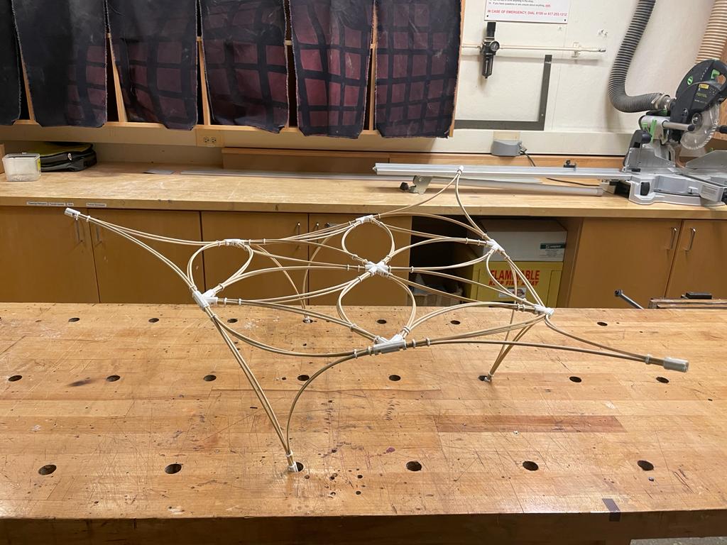
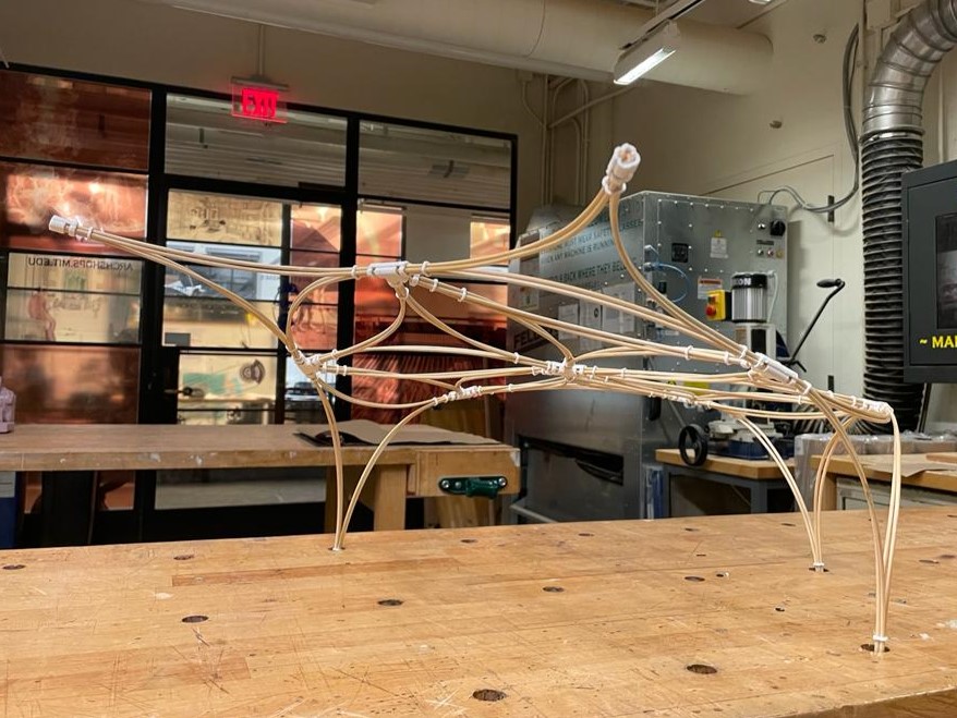
The active bending property of bamboo is utilizedin the design of a reconfigurable modular system. The modules are constructed by bundling bamboo at their ends.
Modules can be assembled in differentarrangements on the ground and lifted into placein various configurations. The ends ofthe modules can be joined to each other, anchoredto the ground, or free without any connection.Depending on the arrangement of the modules,the structure can be reconfigured. Since themodules are interconnected, the bending occurs atboth the module scale, and the global structurescale.
Due to the activebending property of bamboo, the bendingtransformations can be undone since there is nopermanent damage incurred from the elasticdeformation.
The prototype was utilized to test the transformable aspect of the modular system by assembling themodules in 2D and lofting the module in place tocreate a 3D structure.
3D Printed Connections (Nodes) are uses as connection between these modules.
Documentation
 Configuration 1 View 1
 Configuration 1 View 2
 Configuration 2 View 1
 Configuration 2 View 2
 Configuration 3 View 2
 Configuration 3 View 2
Assembly Process
 Part to whole relationships
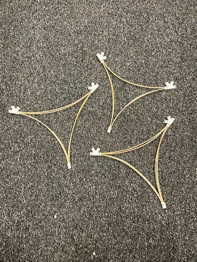 Modules
3D Printing Tests
 Single Module - Testing with the connections before printing a bunch of them
 Removing support from 3D print.
3D Printing Tests
 Completed 3D print. I am using the Sindo Printer here. Followed in default instructions from the Archsite. Nothing Fancy
 Checking up on 3D print midway to ensure that there's no errors. Included support just in case.
WEEK 4 ELECTRONIC DESIGN
I worked on this in KiCAD. I picked KiCAD instead of the other two since I don't want to pay for fusion after my educational licsence.
I was also confused by svg-pcb. There isn't widespread tutorial on this online since it is a new platform. Therefore, as a beginner, I think KiCAD is the best option for me.
PCD board
KiCAD
This is the final iteration of the circut which is closely put together
Planning out the paths to see if I could connect all my pins. But the layout was not set. THerefore , the board looks very big since I am just playing around.
Switching to PCB side after schematic design. It looks like my schematic design shows that the pins are crossing over too much, so I rotated it.
Schematic Design
Final Schematic Design, where I added, a button, resistors, and a LED which would help with the general functions of the board.
I wanted to have two pin connectors, one with pins SCL SDA for I2C communication with a network of IMU / accelorometers. I am not sure how it would work, but this is what I decided that is correct
Simiply putting components in the schematic design page. Putting XIAO board, and putting a bunch of pin connecter modules to see which ones I want to use.
WEEK 5 ELECTRONICS PRODUCTION
My PCB - Printed Circut Board
Project Description
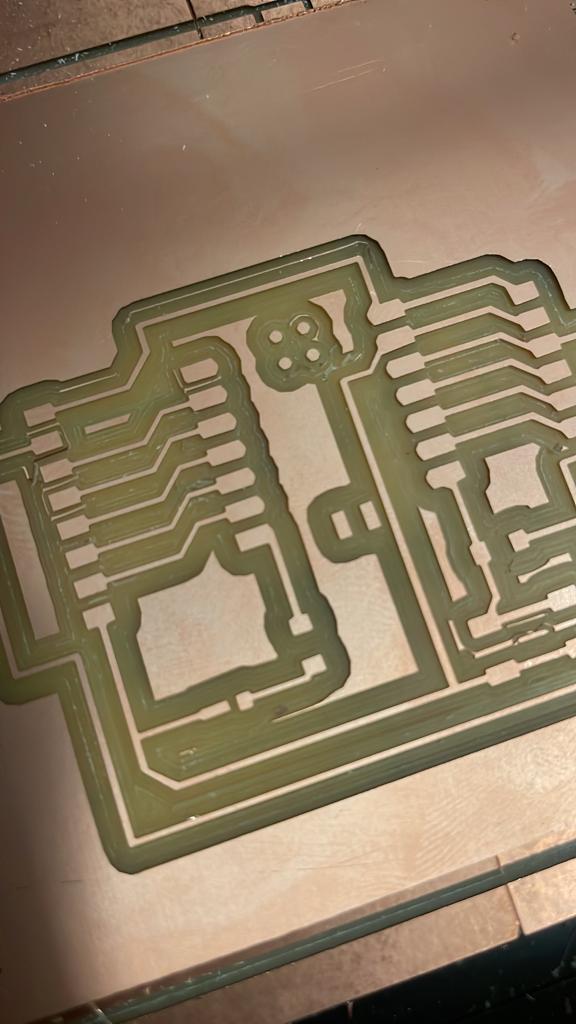
I slightly modified the layout of my last week's design. This week, we printed our digital circuit board design into physical circuit boards.
The printed picture above is the final succesfull outcome of the printed circuit board.
Final Documentation
Machine milling the PCB board.
Final Documentation
Running code to test if the led on the circuit board blink. Here I coneected it to pin number 6 and it works.
Final Documentation
Running code to test if the button work by blinking the led when you click on the button.
Process
 Setting up the board in the modela
 Using modules to controll the origin point
 Start Milling
 Finish Milling
 The outcome was abit fuzzy, so I am zooming in to see how bad it is
 Turns out it is pretty bad, so I reprinted another board and made sure the bit is new this time
 Turned out pretty well !
 Cleaned it up, and I started soldering
 The led was a tricky part ! Since it have orientation. Have to look up online to see which side goes to ground
 Finished soldering :D
PCD board
Running a program in it :D
Project Description
I need a base for the final project! Intiially thinking about milling a pattern.
But decided to change my mind and mill something so that I can put a cork sheet later. The cork cutting I am planning to do it on the zund for my wildcard week.
I discuss my idea of milling a patten with the Shop TA, we decided it is ia better idea to do a base that would hold the cork sheet.
Process Documentation
MasterCam
Learning mastercam with chris at the shop first. This means just going through the software, and understanding what the layers mean Chris actually have this file ready so he just went ahead and explan to me what each layers meant.
Seeing the simulation of what the mastcam toolpath would look like.
This is what the gcode generated looks like. This G code can also be used for like other machines.
Taking a closer look at the details just to be sure that my toolpath is going all the way down.
Looks like it's all set !
This is chris showing me how to plug the usb in the side of the machine first. Select the file and run it on the CNC mill.
This is where I selected the toolpath type. We are just doing the contour since I ended up milling two parts and assembling it into one.
The CNC doing it's job ! The first time the drill bit broke. This photo is actually from the second time this is running.
Clamping and gluing evertyhing down. I actually have a circular base and and a ring. Therefore those two have to be glued together.
WEEK 8 Input Devices
I am planning to use Accelormeter for final project. I mainly want the oreintation of a moving part.
I mainly need to get the orientation for accelormeter.
I used the MPU 6050 after a series of research and a lot of recommendation online for it.
I am planning to use twelve of these so I have to get something that is of reasonable price too.
Test Results
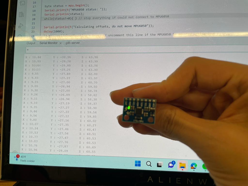
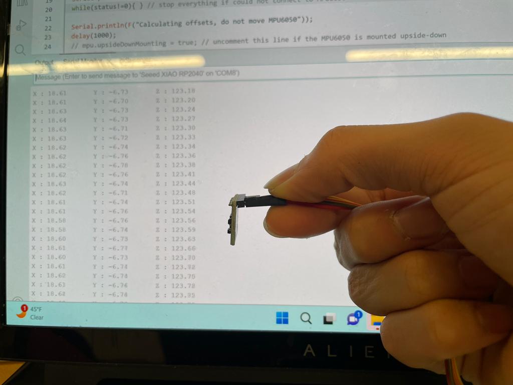 Testing Accelormeter at different angles to see if the values changes
 Testing Accelormeter at different angles to see if the values changes
 Testing Accelormeter at different angles to see if the values changes
 Testing Accelormeter at different angles to see if the values changes
Testing Accelormeter at different angles to see if the values changes
What didn't work
Somehow failed with my XIAO PCB, so the above I plugged the accelormeter directly to my XIAO RP2040. a spare one that I have
Somehow it works on my spare XIAO board, but not on my PCB one. I actually don't know the reason why, however, I need to look more into it.
Wiring
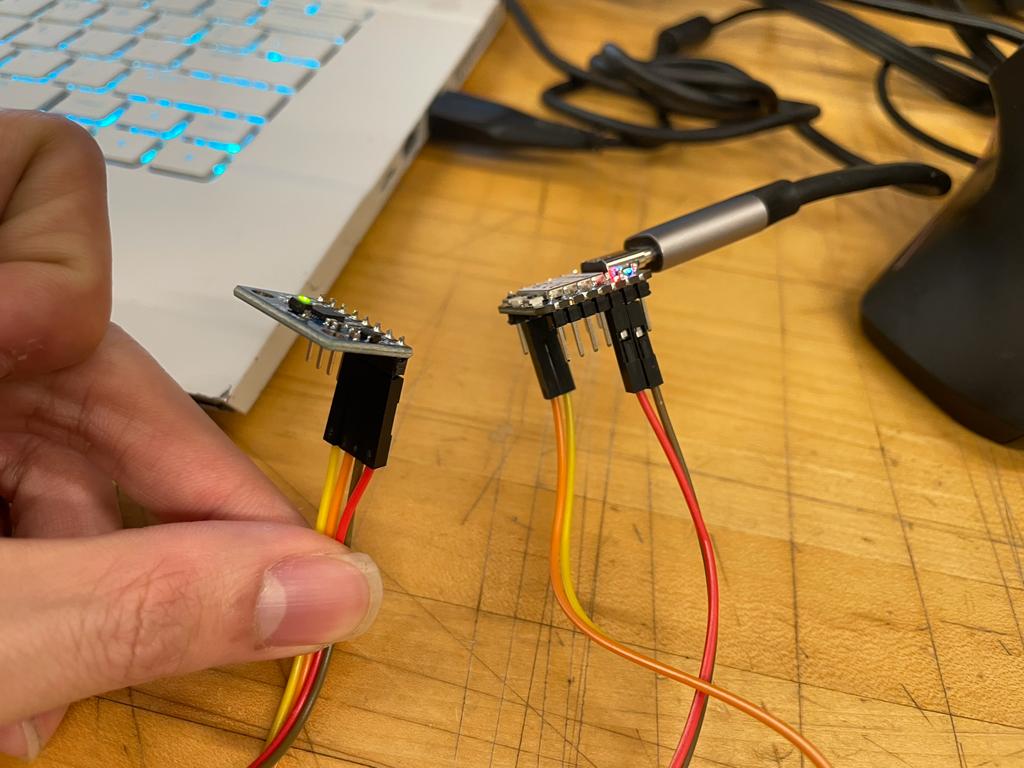 Connecting the 3v3, Ground, SDA, SLC. I learn the SDA is for the data, and SLC is for the clock
 Another angle of this. To do this I pulled up the data sheet of the MPU 6040 and also the xiao board.
Coding in Arduino
Arduino Code -> this was one of the example files to get the angle of the x y and z . I uploaded the example code and it work.
              #include "Wire.h"
              #include

              MPU6050 mpu(Wire);
              unsigned long timer = 0;

              void setup() {
                Serial.begin(9600);
                Wire.begin();

                byte status = mpu.begin();
                Serial.print(F("MPU6050 status: "));
                Serial.println(status);
                while(status!=0){ } // stop everything if could not connect to MPU6050

                Serial.println(F("Calculating offsets, do not move MPU6050"));
                delay(1000);
                // mpu.upsideDownMounting = true; // uncomment this line if the MPU6050 is mounted upside-down
                mpu.calcOffsets(); // gyro and accelero
                Serial.println("Done!\n");
              }

              void loop() {
                mpu.update();

                if((millis()-timer)>10){ // print data every 10ms
                Serial.print("X : ");
                Serial.print(mpu.getAngleX());
                Serial.print("\tY : ");
                Serial.print(mpu.getAngleY());
                Serial.print("\tZ : ");
                Serial.println(mpu.getAngleZ());
                timer = millis();
                }