Process
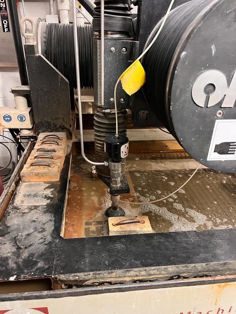
I began by setting up the foundation for my machine, starting with the dimensions I wanted. I took some time to calculate the size based on my preferences.The choice of size wasn't arbitrary; it was a deliberate decision shaped by the practicalities I had in mind. I considered the available space, the required range of motion for the plotting mechanism, and the overall balance between size and stability.These calculations became the starting point for the entire project, so I adjusted the model to fit the dimensions that I cut the extrusion and the base plastic.
I have been following Jake and Quinten's machien building progress pretty regularly throughout the semester and talking with them about motion control for my plotter. I went to the CBA shop and got introduced to some of their machines. This made the dimensioning of certain parts much simpler.
Throughout the semester, I have closely followed the progress made by Jake and Quinten in their machine-building endeavors. I visited the CBA shop many times and got some insights into machine dynamics which helped as a starting point for certain parts and dimensions of my designs.
I started by designing components around the extrusion so they could fit many sizes and designs of similar plotters. These components serve the purpose of both ensuring precision in fitting onto the extrusion and acting as parts to binding the entire assembly together.
In the wild card week, I worked with Shah from the arch shops to create waterjet files. These files were then used for the initial prototyping of my project. I chose the laser cutter to craft the base and the Z-axis actuator. These components formed the basic structure of the project and held it together. I also used the waterjet to make the Z-axis actuator which used a servo for movement.
Z Motion
I spent a good chunk of time getting the design just right for the part that lifts the pen, called the Z actuator. At first, I thought about using a small stepper motor, but I ended up going with a servo because it seemed more precise. The servo makes the pen go up and down by pivoting. To make it happen smoothly, I used waterjet cutting to shape it and added a rail I ordered separately. This way, the pen moves up and down without any hiccups. The focus on nailing down the Z actuator design was all about making sure the pen lifting is accurate and works seamlessly.
Core XY
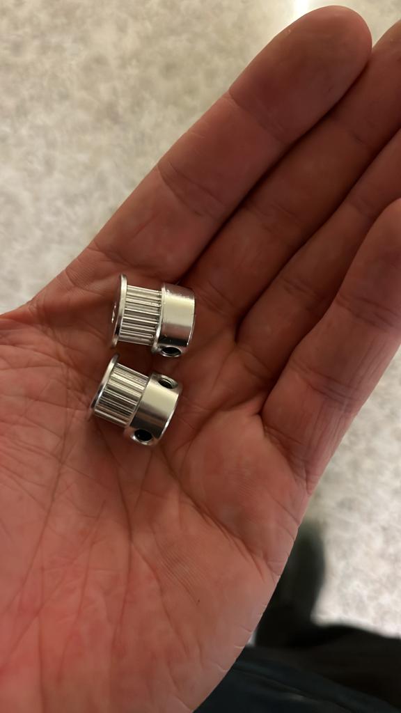
In selecting a motion control system for my project, I opted for Core X because I only intended to use only two motors. The Core XY system caught my attention because of its history at MIT and I was interested in how to code its movement. I think the only downside to this was the amount of pulleys I had to order. This became especially annoying because my order for these got extremely delayed and I had to salvage them from a bunch of different shops around campus to complete the machine.
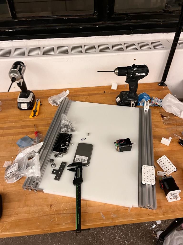
Production
The hardest part about production was waiting for the print. Based on Neil's advice I tried to do things that took time way ahead so I could spend a bunch of time debugging. The prints in total took about 30 hours but I ran many simultaniously so it took about 10 hours of waiting to get all my files. Some of the supports wouldnt deattached so I had to run a couple extra.
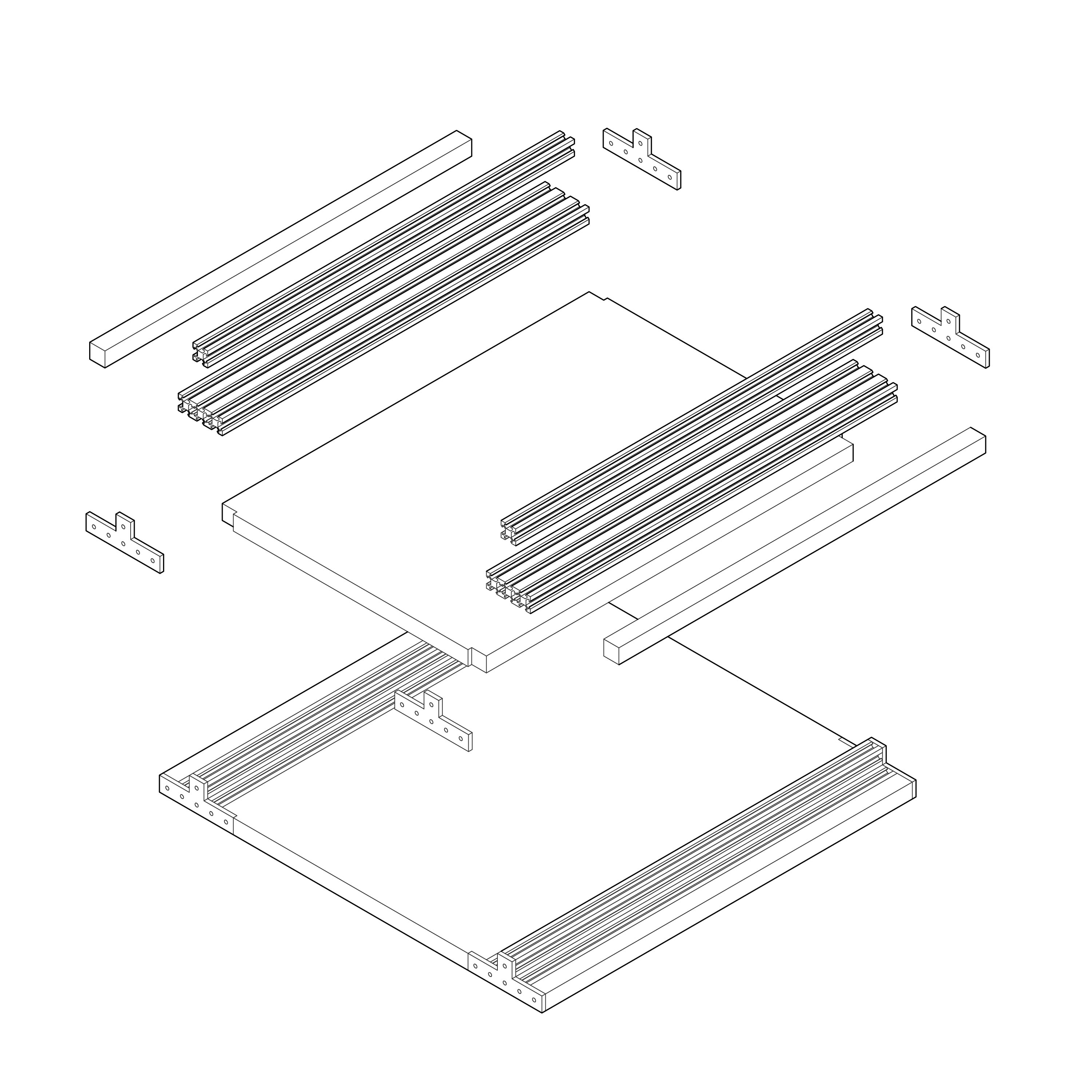
Base
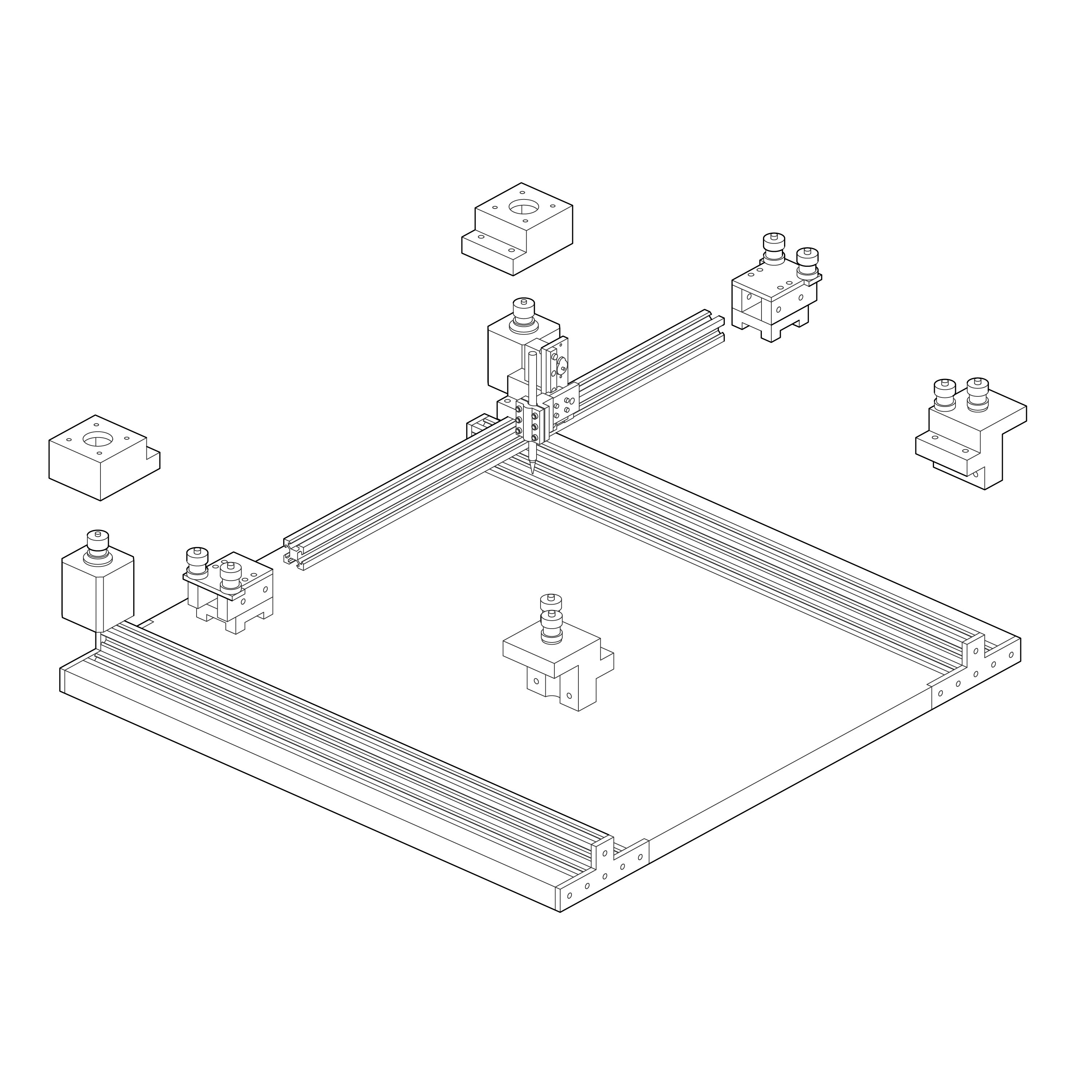
The base for the plotter was designed around a couple base components: 1 unit 20 x 20 mm aluminum extrusion for bearing to roll on, 3 unit 20 x 60 mm aluminum extrusion to allow for future mounting of different accesories, a polyetylene base so the machine could be sturdy yet transulcent to be put on a light box.
I waterjet cut the end caps so the rigid metal could brace the extrusion. I tapped both the end caps and the holes in the center of the extrusion with an m5 size hole so I could secure them.
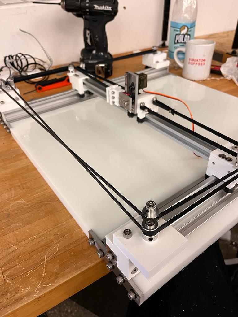
Core XY System Components
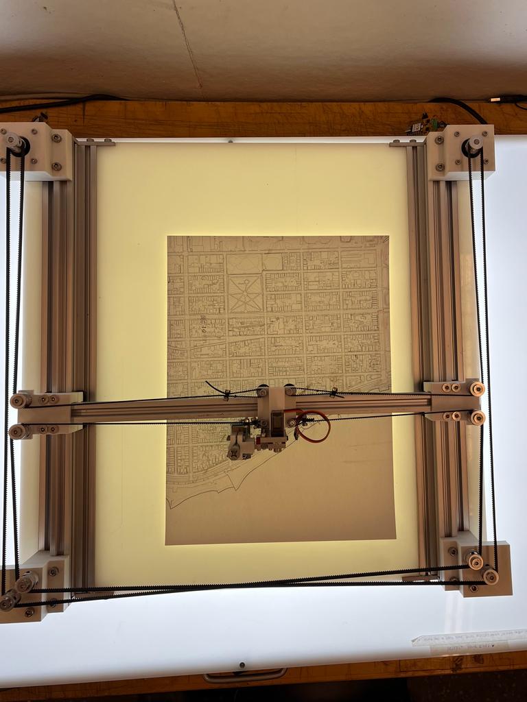
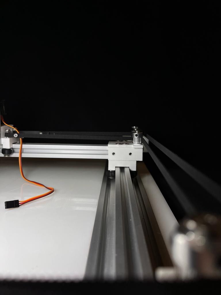
I based the core xy mechanism on the orignal prototype that I saw at the MIT Museum. Here is a link to it: https://corexy.com/corexyr1/index.html . I designed 3D printable parts to attach to the rails in the most sturdy way possible.
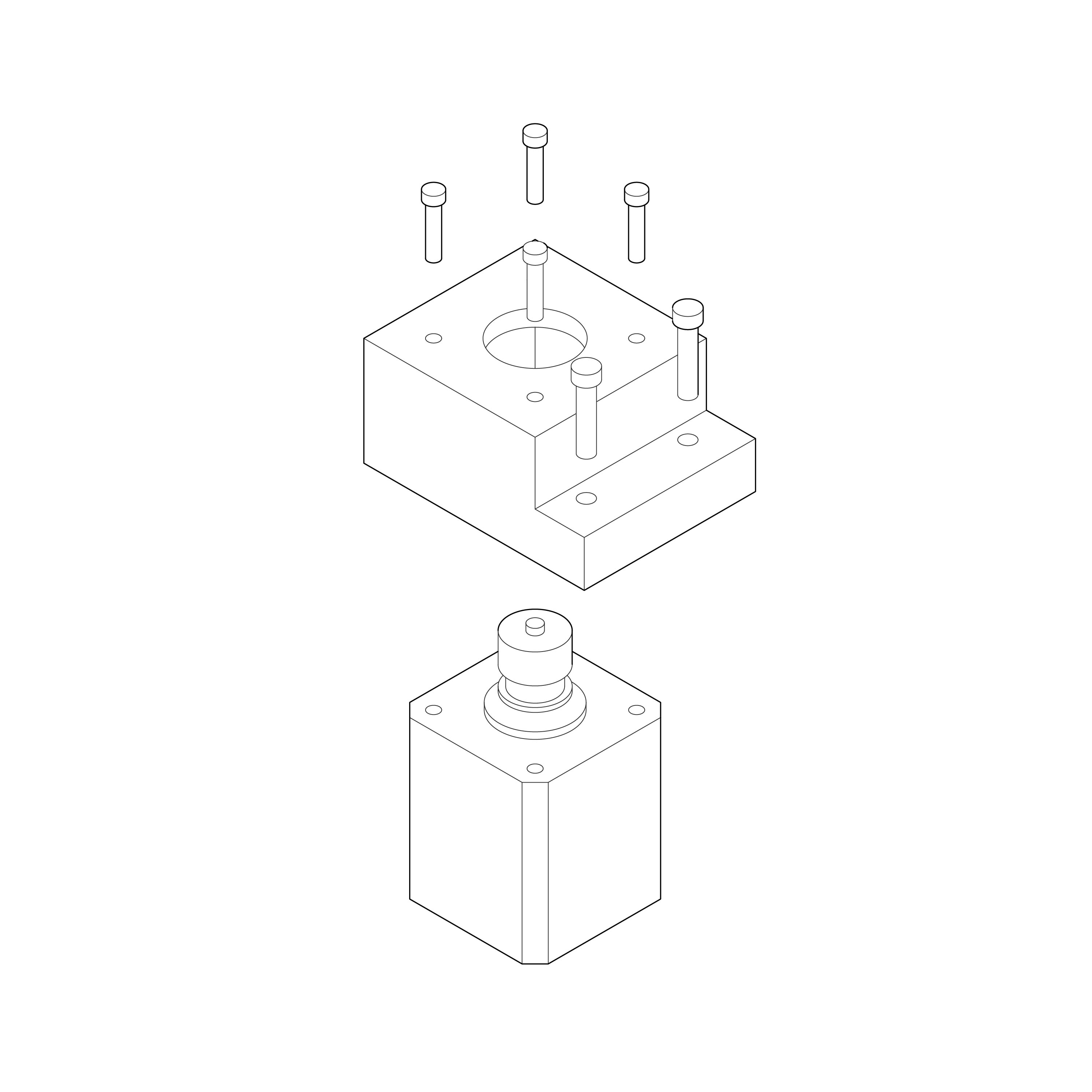
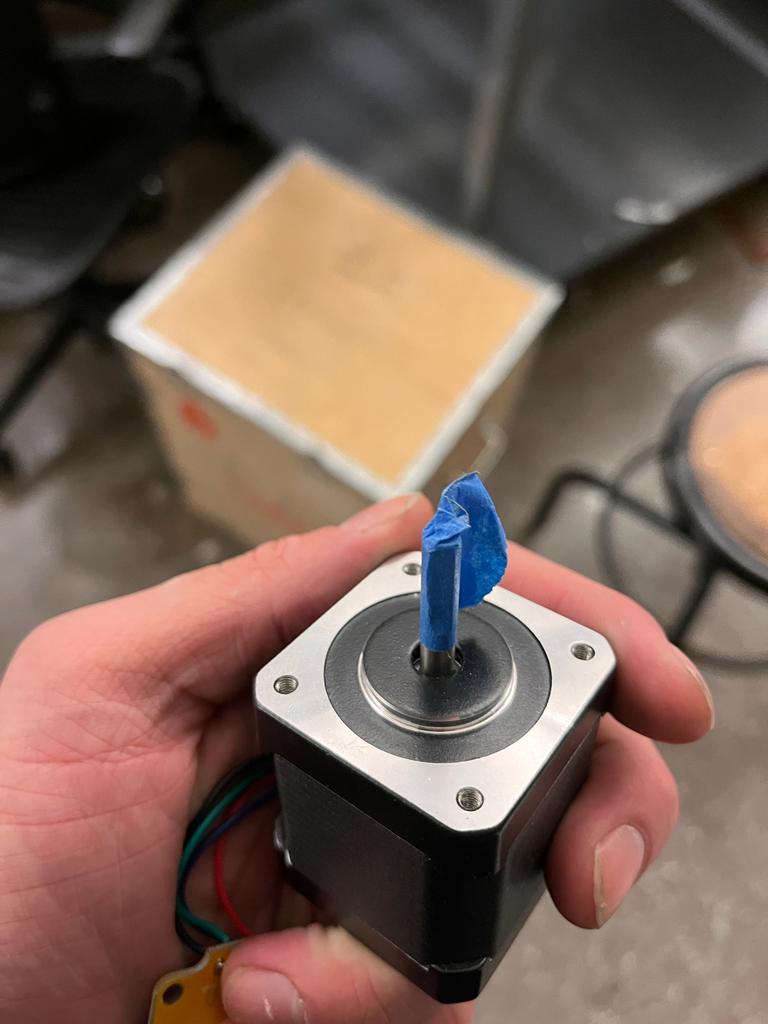
The Nema 17 motors that I used are mounted to a box which is mounted to the frame at the size. This way the motors can be oriented vertically.
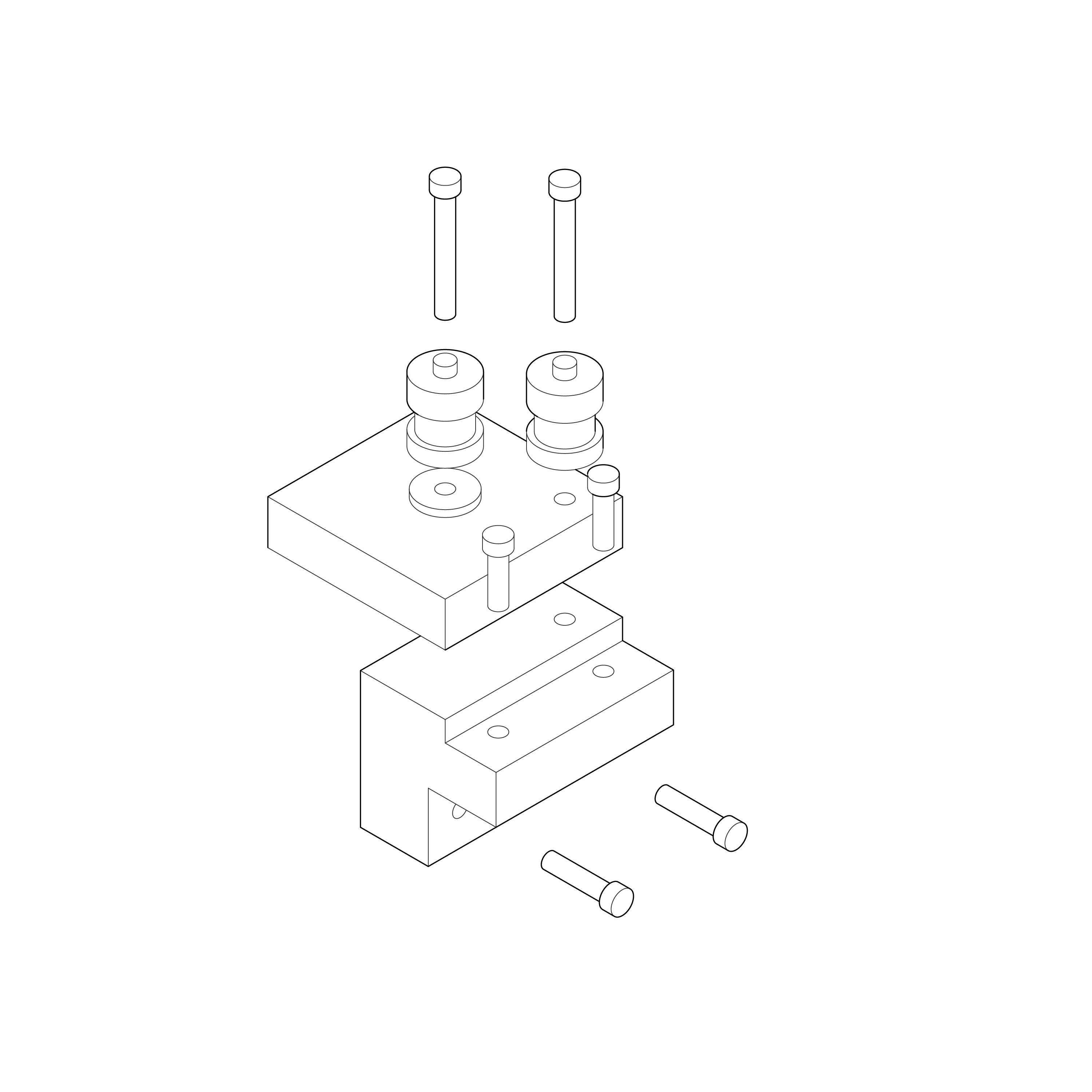
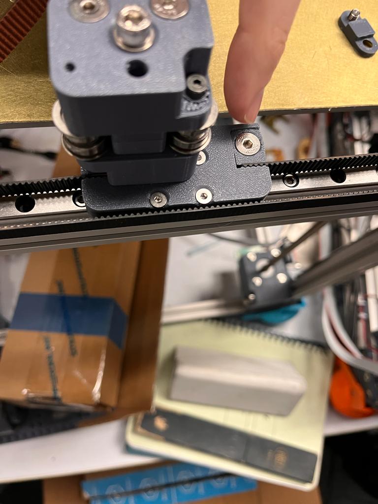
The opposite size requires two pulleys to create the core xy motion. I used the machine screws that were being mounted to the frame as mounts for the pulleys to rotate around.
Lastly, the rail in the other direction was also designed so it could be mouted with the pen actuator.
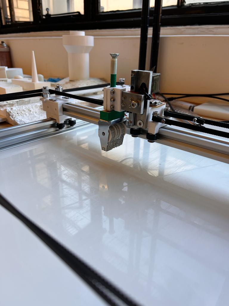
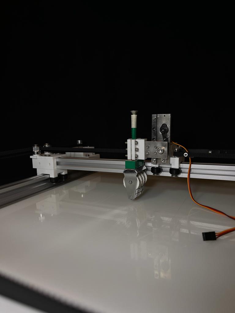
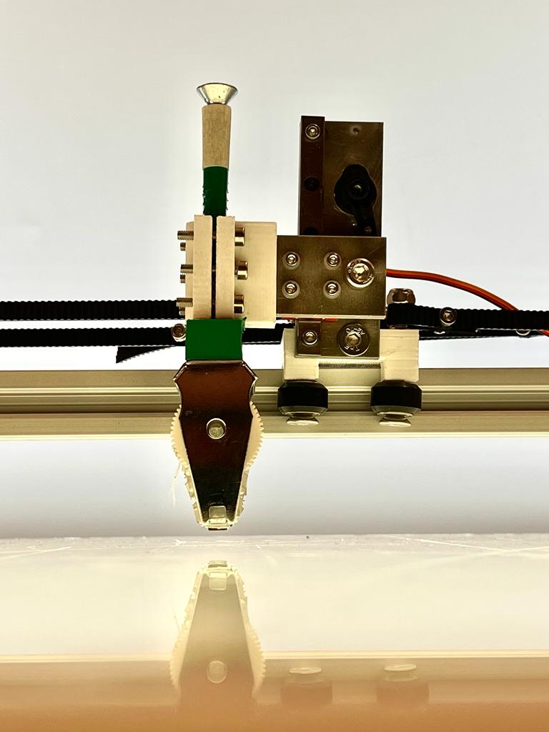
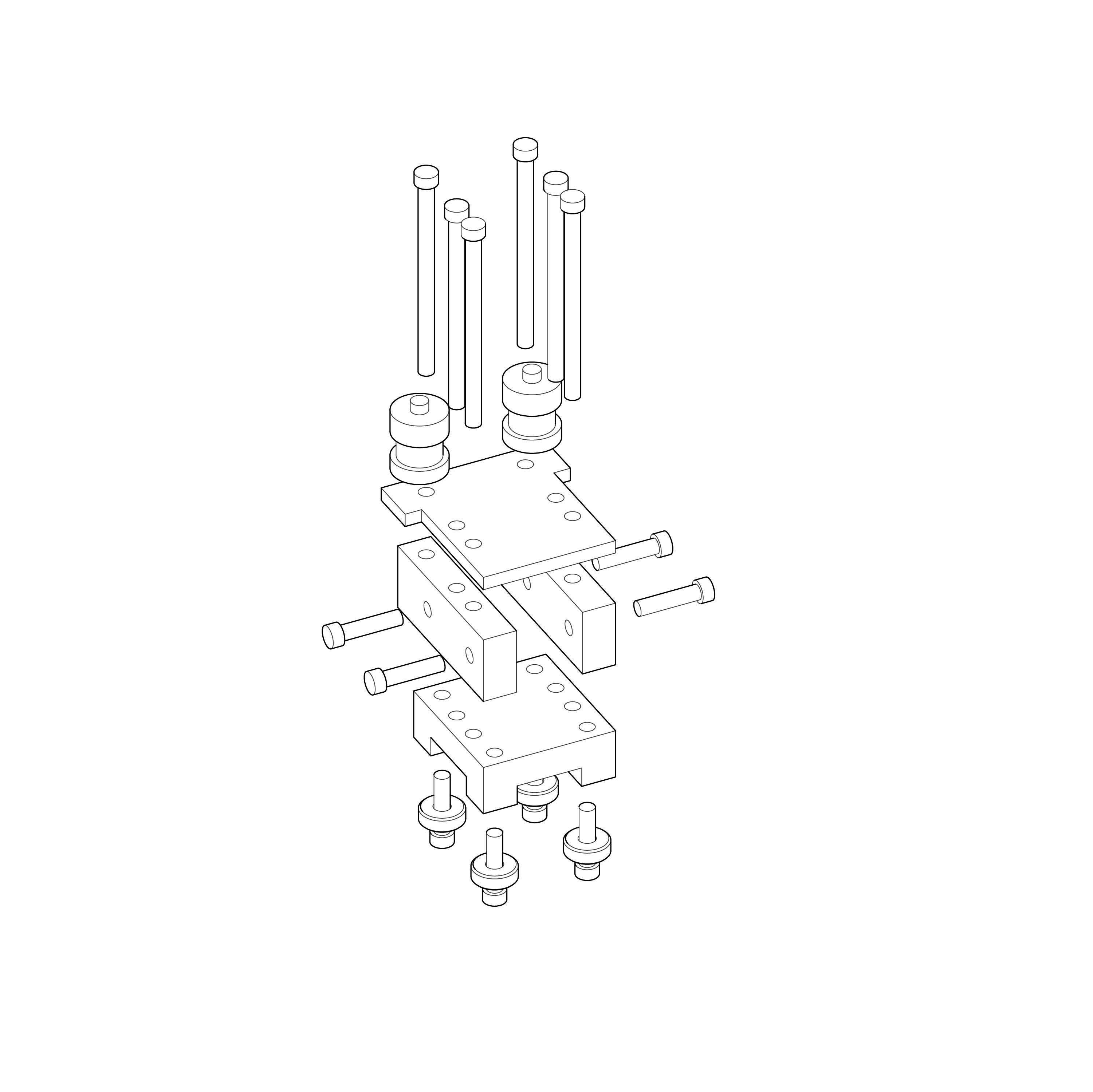
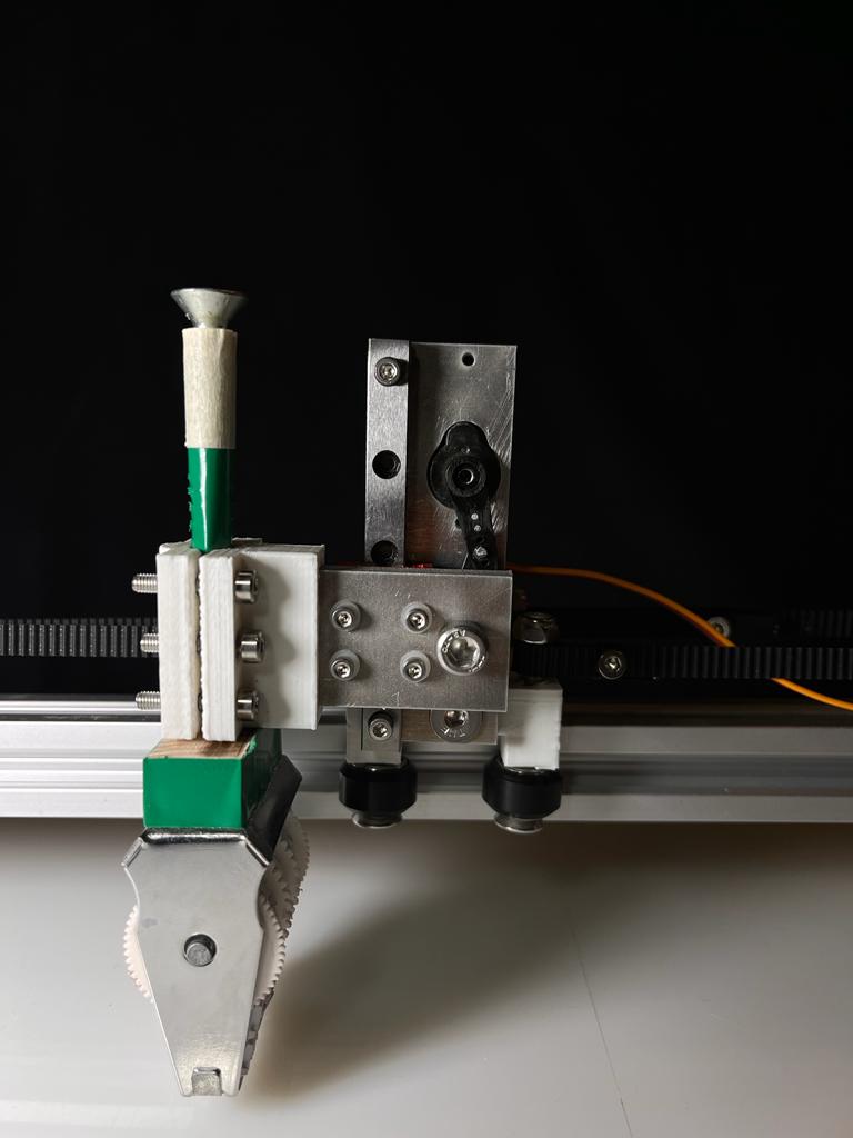
Pen Actuator
The pen actuator was one of the first things I designed in this project. I wanted it to serve as a universal mount for different pens and stamps. I used the waterjet mostly to cut 5mm aluminum to mount the servo and include holes to mount to the rail and linear rail for the z motion.
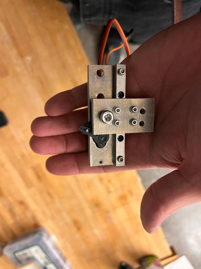
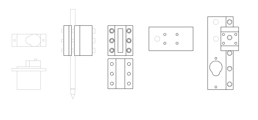
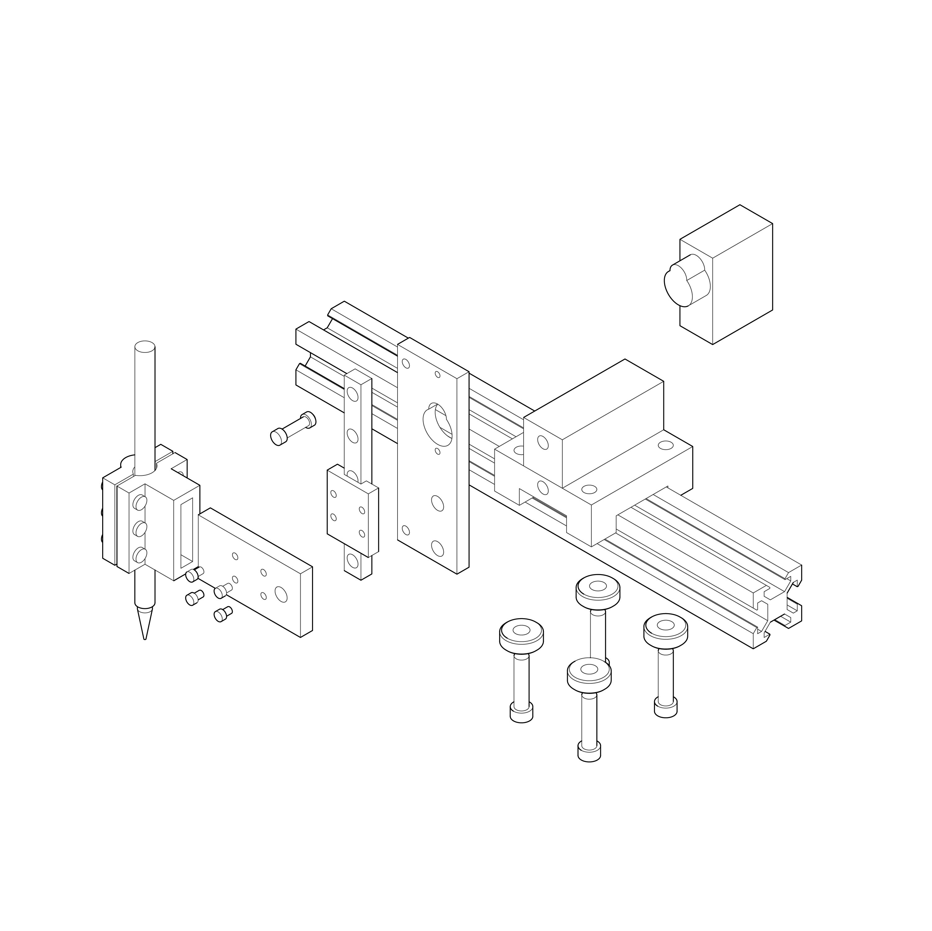
I used the parts included in the servo kit to act as a pivot to translate the radial motion into a linear up and down motion.
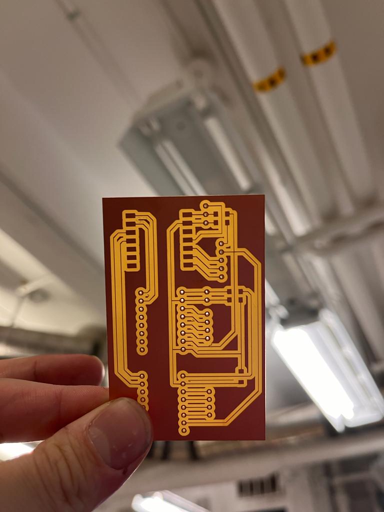
PCB
I began by milling a board that incorporated several step sticks connected to a Xiao RP2040. Additionally, I integrated a servo and a rotary encoder knob into the design. Despite my efforts, the initial setup faced challenges, and despite multiple attempts at resoldering, the issues persisted.In response to the encountered difficulties, I opted for a change in approach. I transitioned from the milled board to utilizing pre-made module boards, aiming to enhance the overall reliability and functionality of the project.
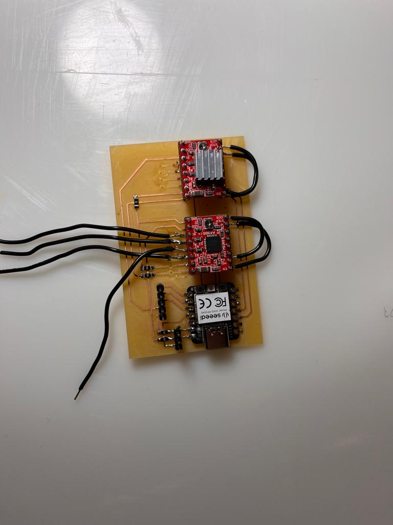
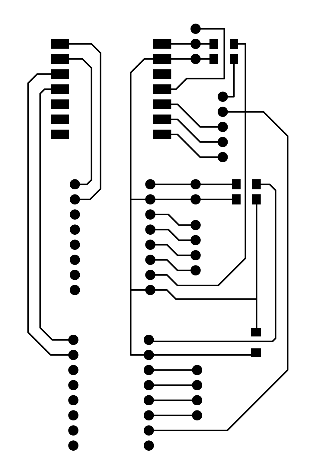
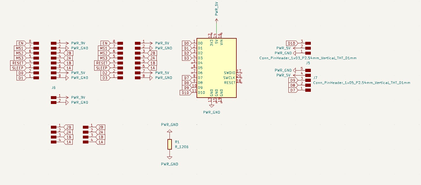
The step stick required a decoy stick or an external power source greater than what the xiao supplies to run the motor. I heard some horror stories about peoples computers getting wrecked from these and other issues that arose, so I opted to use the motor drivers from modular things that Jake and Quinten provided. I got a pcb blank and soldered the parts on in my shop.
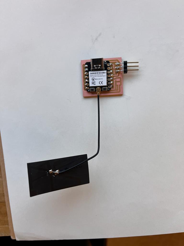
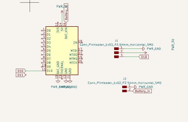
To drive the pen actuator I wanted to use an esp32c3 so I could control it without a cable running across the machine. For now I had to have it attached, but in the future, I designed the pcb to take an external powersource that could be mounted on the rail.
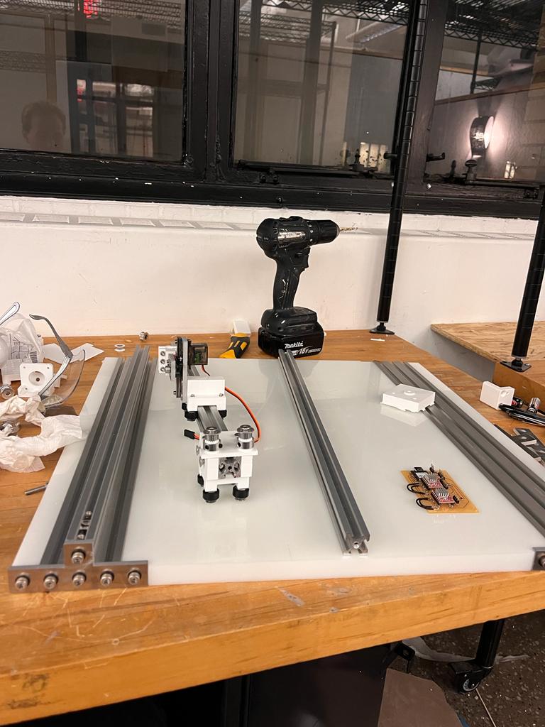
Assembly
When I started assembling the parts, I quickly realized the challenge of dealing with tolerances. If I had more time, I would have liked to prototype more to make sure everything fits just right. The struggle comes in when I put lots of things together — unexpected issues popped up,a classic challenge in integrating various different components and systems. The brackets at the end caused a slight skew that I spent countless hours trying to fix. I also found it pretty hard to put the belts on the rails and get them tight enough
Reflections and Critique
This was my firt machine, ever! Obviously it has its issues and for the scope of the class it reverts to a pretty classic concept, but one that I really wanted to fully understand. I talked to Leo and Quinten after the review to get some feedback on the design to improve. Leo suggested that I focus on making some of the rails more parallel and getting choosing a better servo for the z control. He also mentioned that it could be good to make a smaller system that could be more portable. Quiten had some similar feedback but mostly had some suggestions for how to improve the motor controll based on a system he wrote for his selfie machine that he showed at the MIT Musuem exibit on machines.