PCB Fabrication
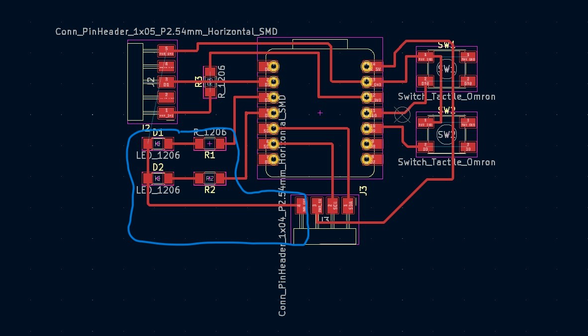
I set out to go through a couple of iterations of a pcb this week after getting comfortable with the KiCad software last week. It was nice to feel pretty confident in the software so I think at this point my biggest constraint is the intuition of what goes where on a pcb. Something that I imagine comes with more electrical engineering study and experience. This is the starting design I used from last week's work which used the Xiao RP2040.
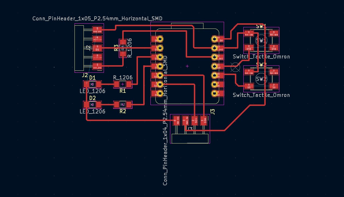
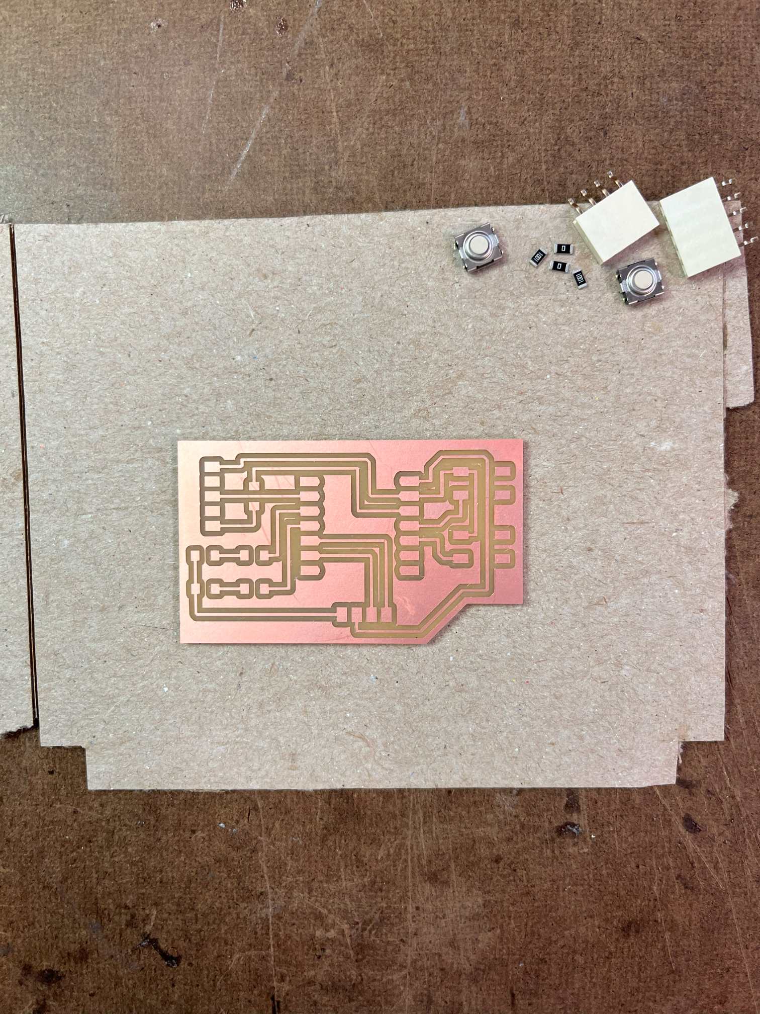
My first design was simple, it was designed to accommodate two potentiometers, an oled display and a button. I wanted it to be small so I tried to cram everything into a small board which required one jumper.
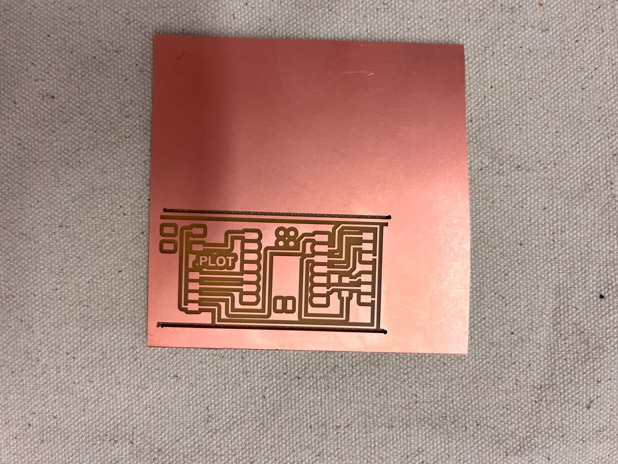
The milling went well, all the traces made with the 1/64 bit were smooth and didn't require any deburring. When I switched to the 1/32 bit however I didn't check the toolpath preview on the mods software and didn't notice that it wasn't going to make vertical cuts. I went back and forth about exporting a new outline png but settled on just band-sawing it off because I wasn't sure what went wrong in the first place. My guess is that I didn't give it enough of a border on the sides.I used this as a chance to change the board a bit (this section focuses on the second iteration) since I had to mill a new one anyway.
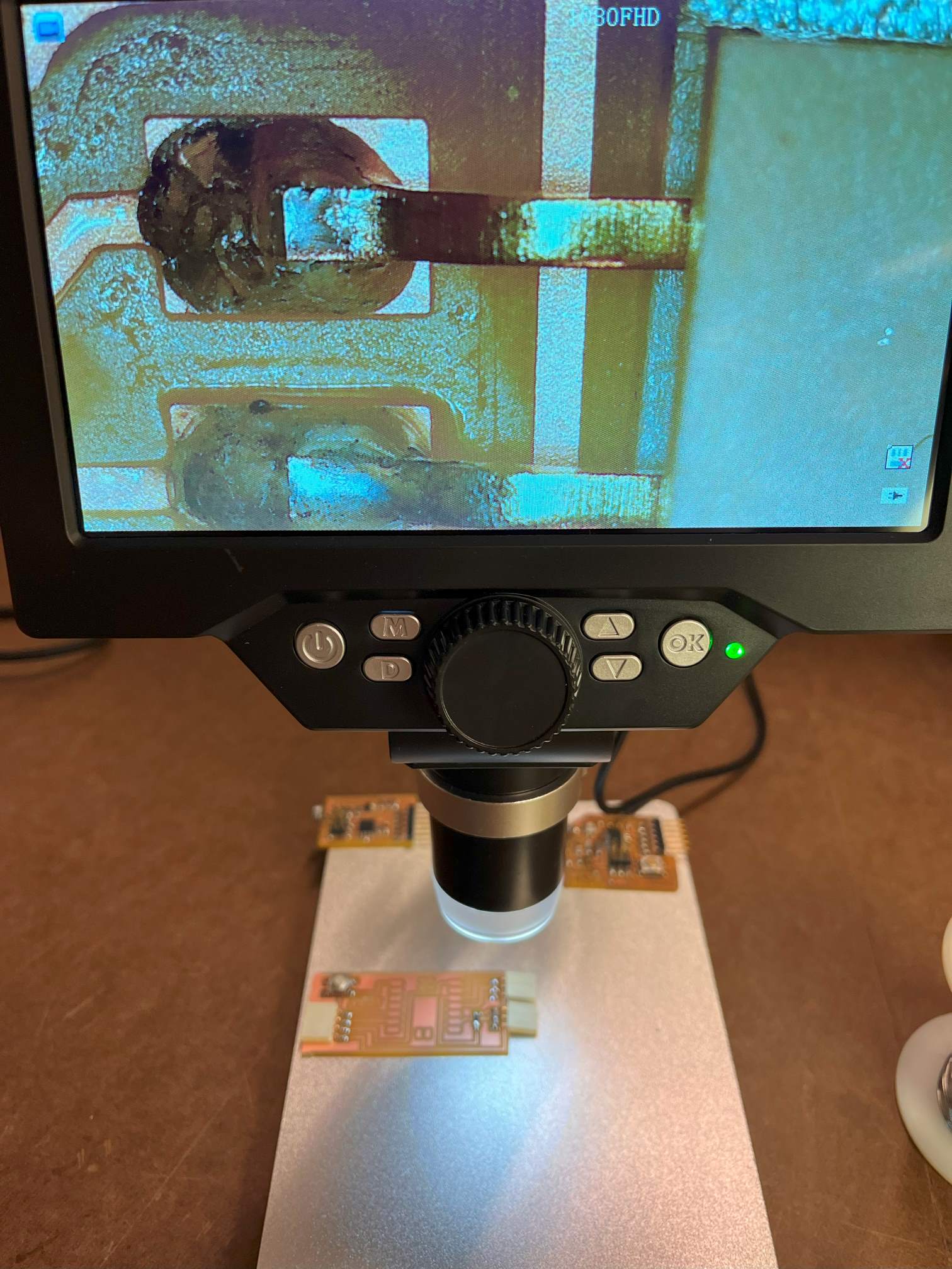
After a couple experiments with the different types of solder, I settled on the lead solder because it was much easier to use and i didnt want to ruin the board or at least reduce the number of things that could go wrong and cause debugging confusion.
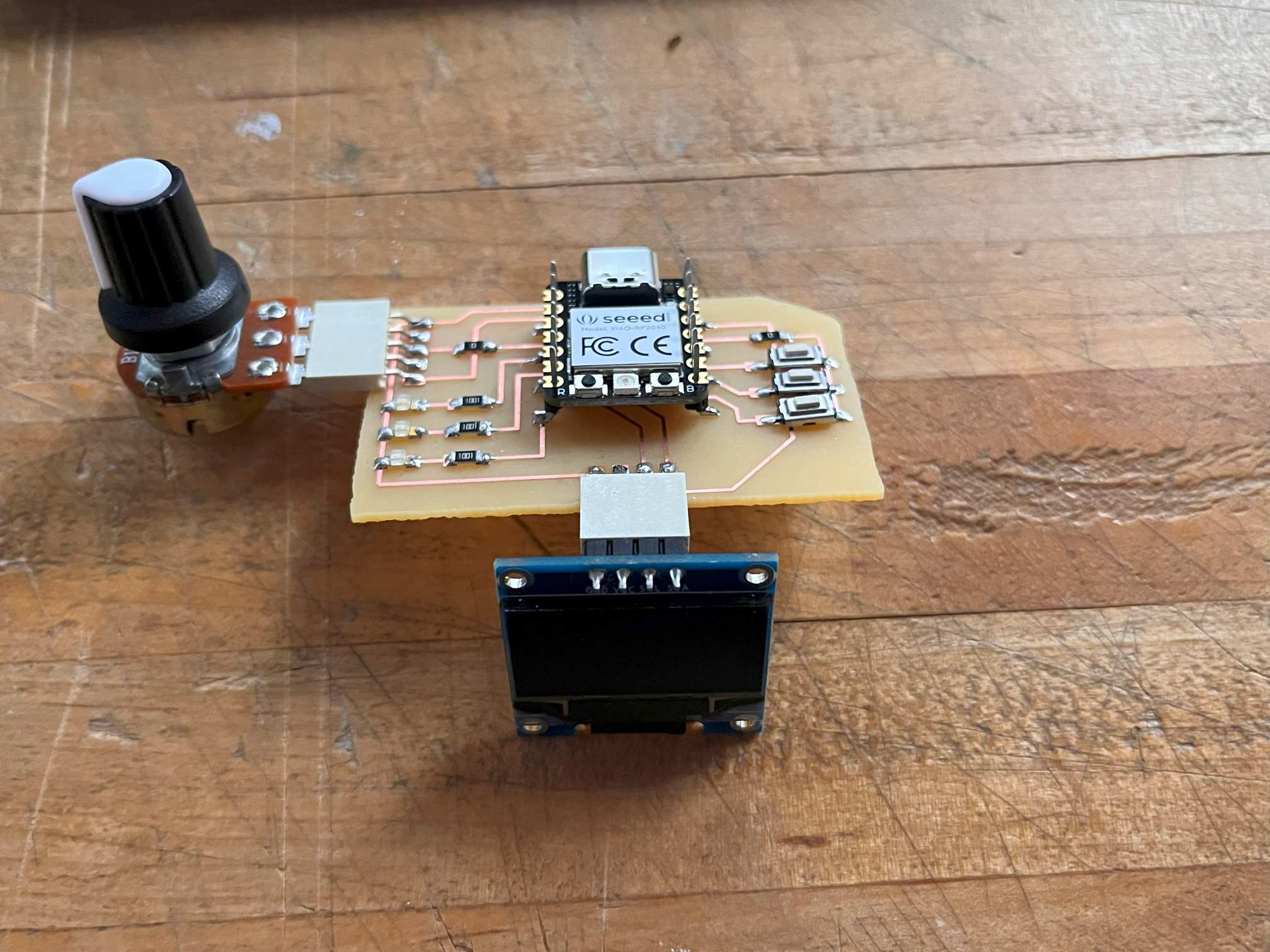
Despite the hiccups I was relieved that everything went well and all of the potentiometers worked. There was one thing that bothered me however which was that I wasn't able to plug the potentiometers straight into the board because the spacing of the outputs are double that of the standard pcb grid. I also realized after playing around with the board and micropython that I wanted an led and more buttons to get comfortable with using more components. I also realized a fatal error in my pcb design where I forgot to add one ground connection.
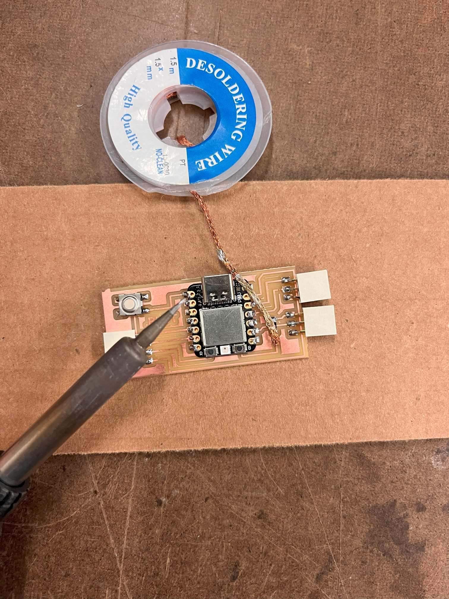
I tried to desolder the microcontroller however I didn't have any luck with the copper braid. I think that there's a hot air gun in the shop but I decided to save that for another moment given that I had a spare Xiao RP2040. For the next iteration, however, I thought it would be a good idea to make the microcontroller demountable incase I wanted to change anything.
PCB Fabrication Part 2
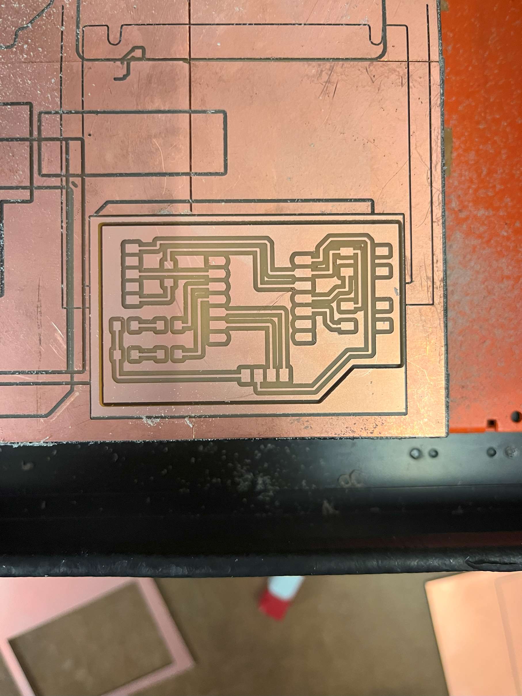
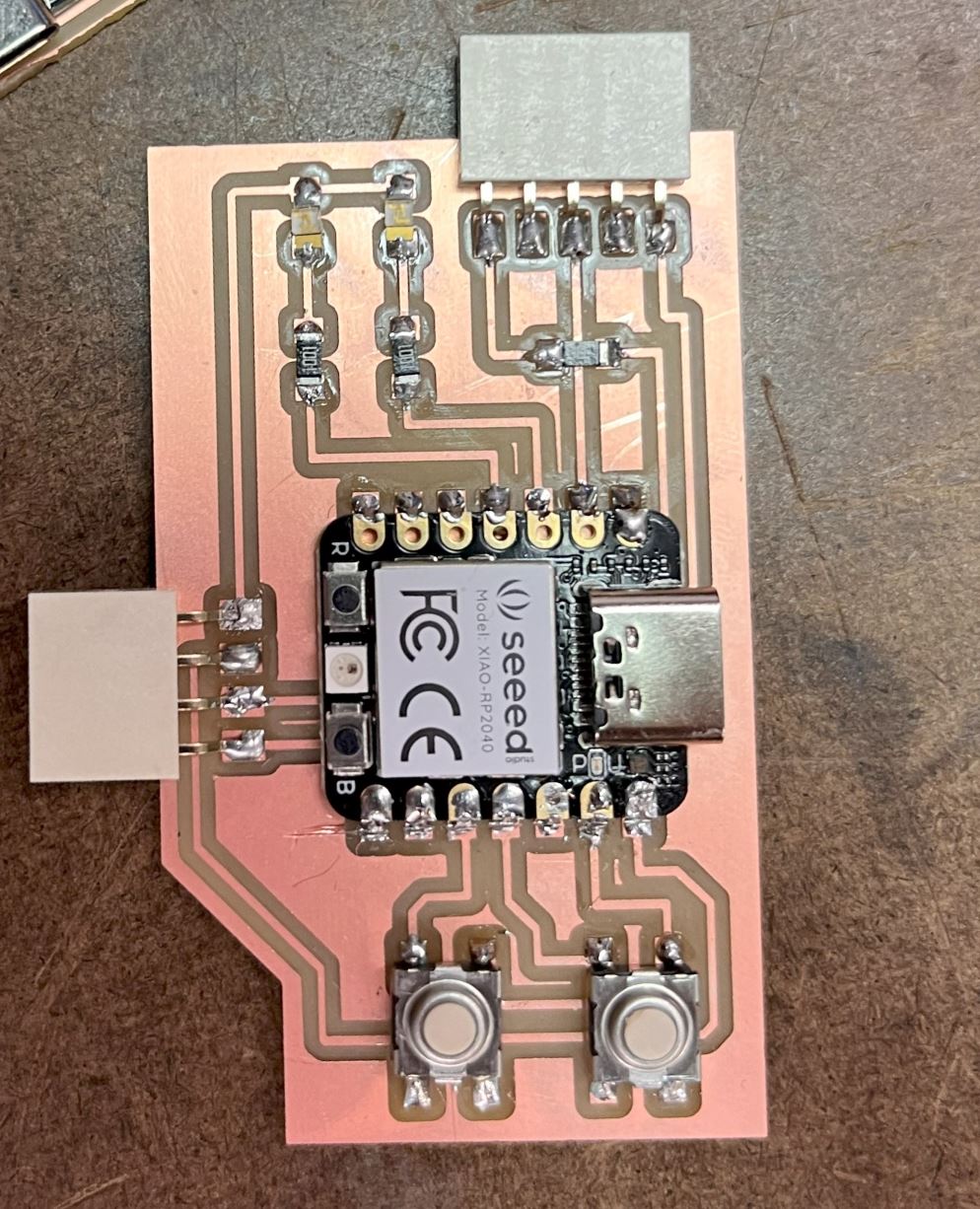
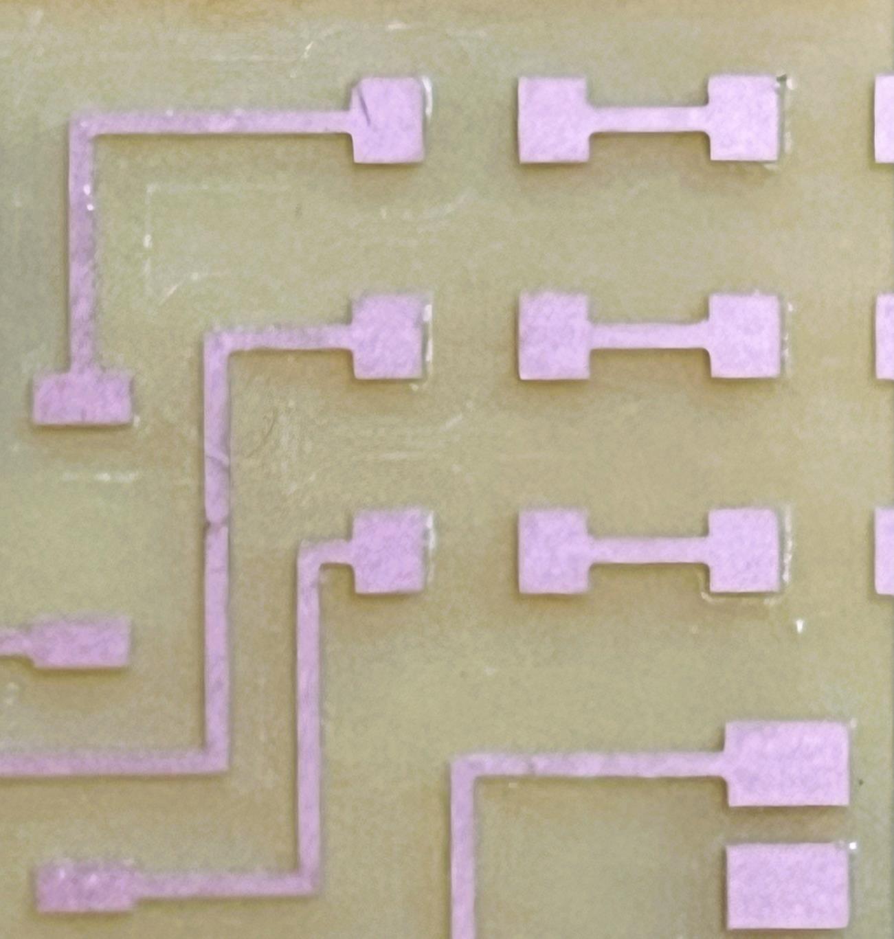
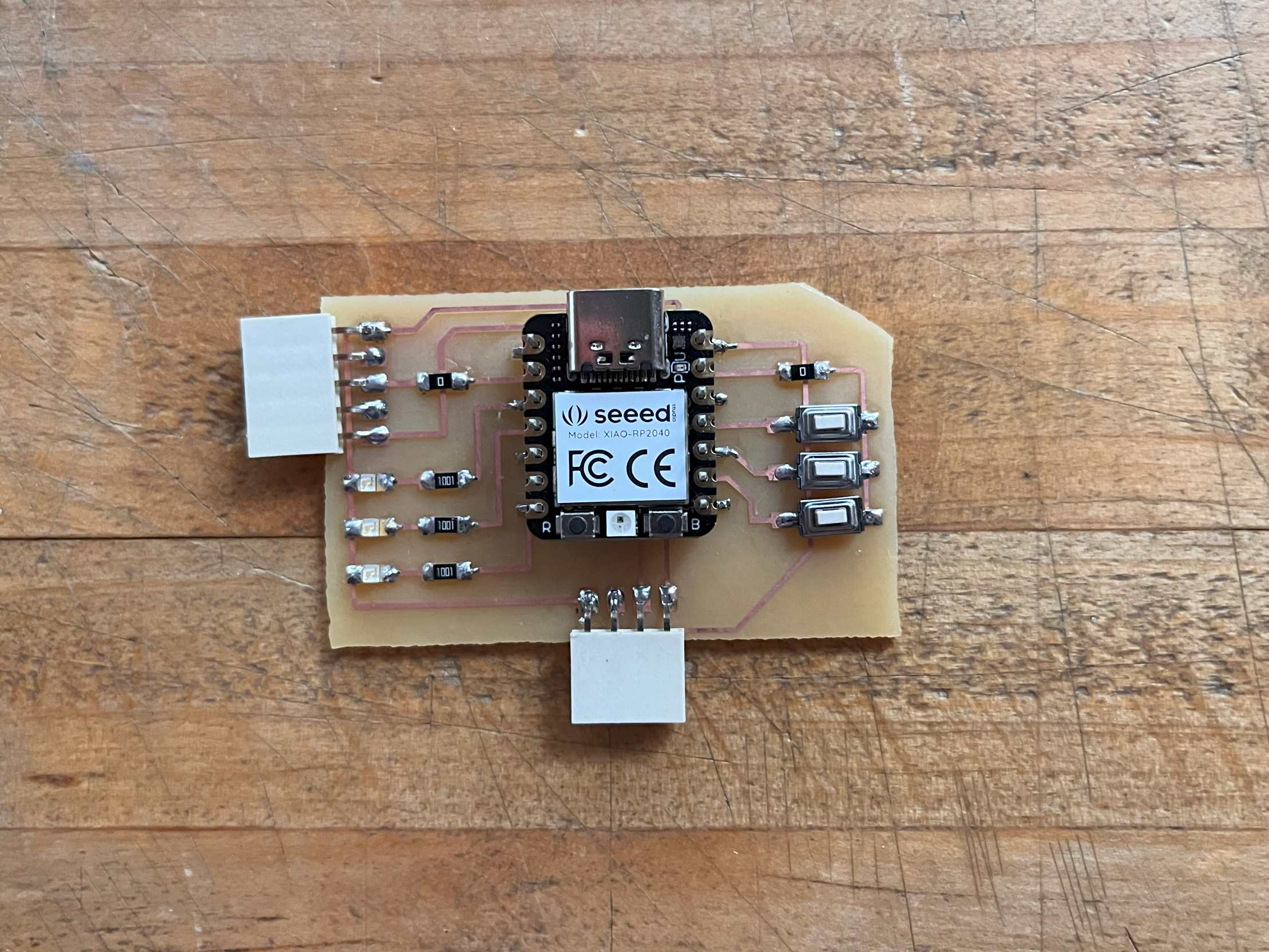
Next pcb i added more buttons and some leds, 3 of each. I also chose to use a 5 output horizontal connector so I could plug the potentiometer straight into the board. I liked the look of the copper wires being isolated on the board so I set the offset paths to zero which takes out all of the surrounding material.
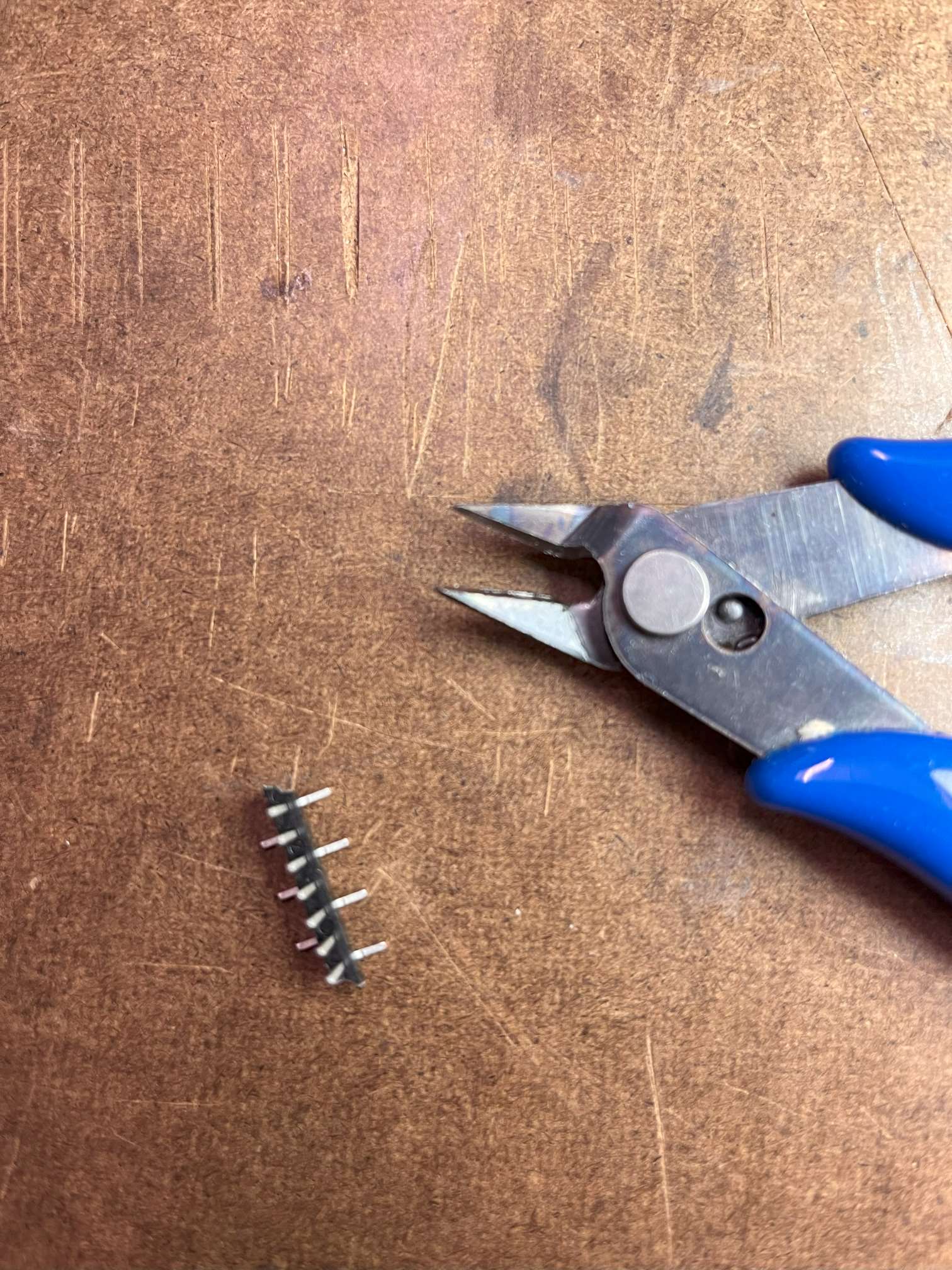
I decided not to solder the Xiao RP2040 directly onto the board so I used these connecters that required a bit of trimming.
This worked better and felt a bit closer to what I’ve been thinking I might need for the final project. One thing I want to figure out is the design of the case for putting the machine in so I can know where to orient things and what wires need to be extended and which components could go directly into the board.
I’m now deciding where to take the pcb and I guess this will go into the dev page for my final project, but I’m happy to say I’m confident in the workflow now. I think just for fun I’d like to design and make some boards that require different types of components like capacitors, diodes, and other power sources.