Rotary Encoder Knob
This week I ran through a whole lot of options for an input device before settling on getting a rotary encoder knob to work for a jogging function in my final project. I visited the Mars Lab this week and got to talk to Jake who had some good thoughts on what to focus on for my final project.
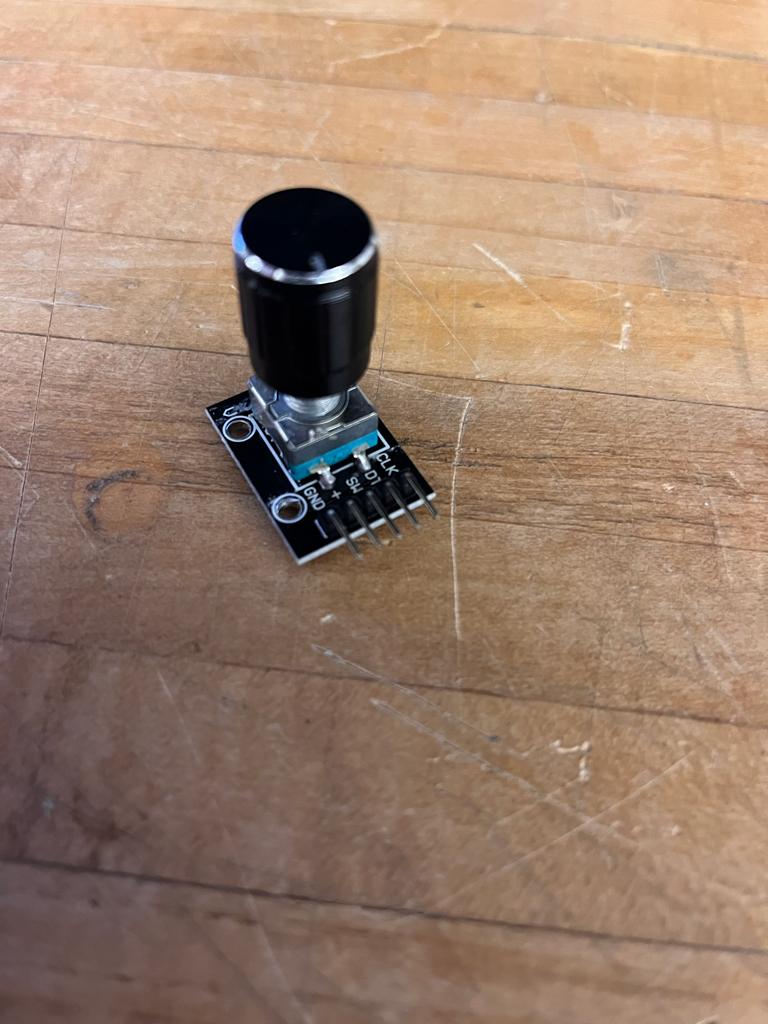
For some prior weeks I played around with potentiometers but since I am using stepper motors for my final project I was interested in the similarity of how information is collected from each device with steps rather than position. The rotary encoder knob that I purchased had five outputs which seemed kind of hefty to add to a pcb if I am going to use 3 (X, Y, Z).
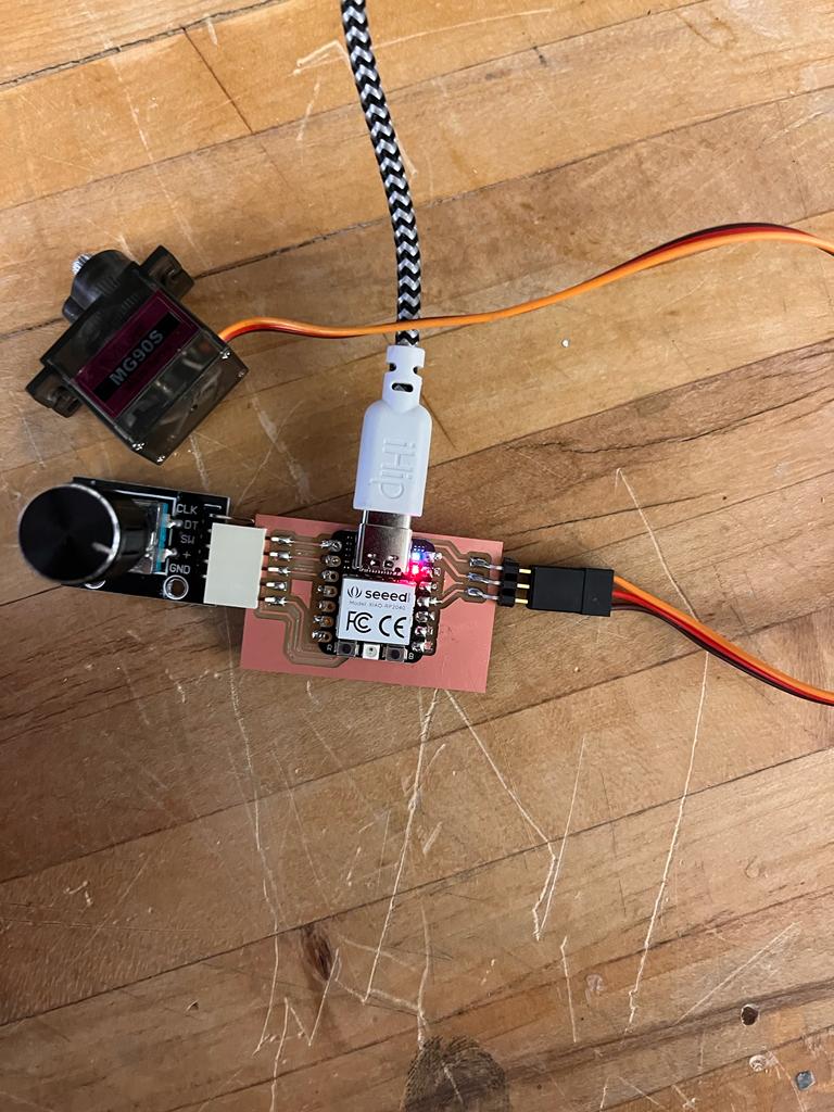
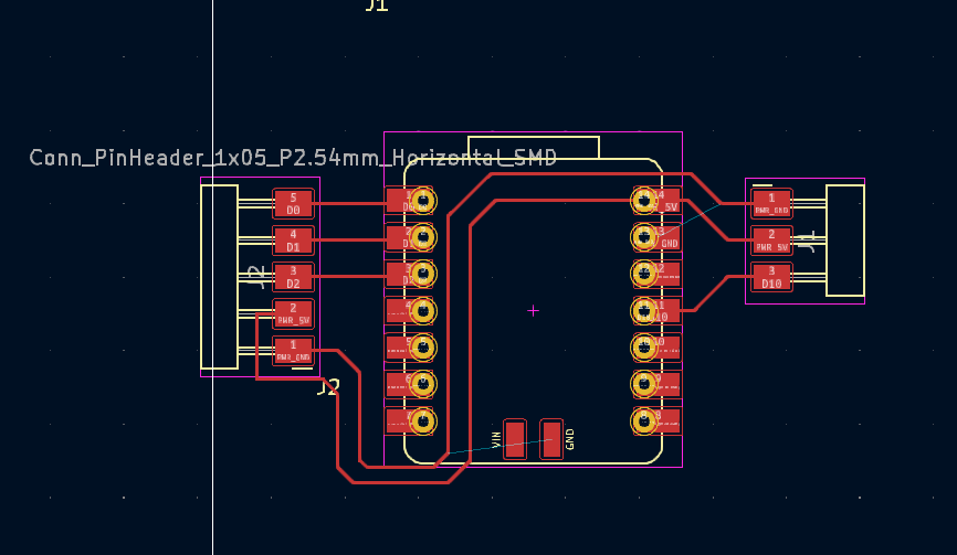
To be fully honest this week almost felt more about the motors than it did the rotary encoders. I spent a good amount of time tinkering with them to see how they might interact, but I will work more on that and document it next week. I wanted to test the rotary encoder knob with something physical other than my computer reading it, so I threw on three pins for a small servo to attach that I could control via the knob.
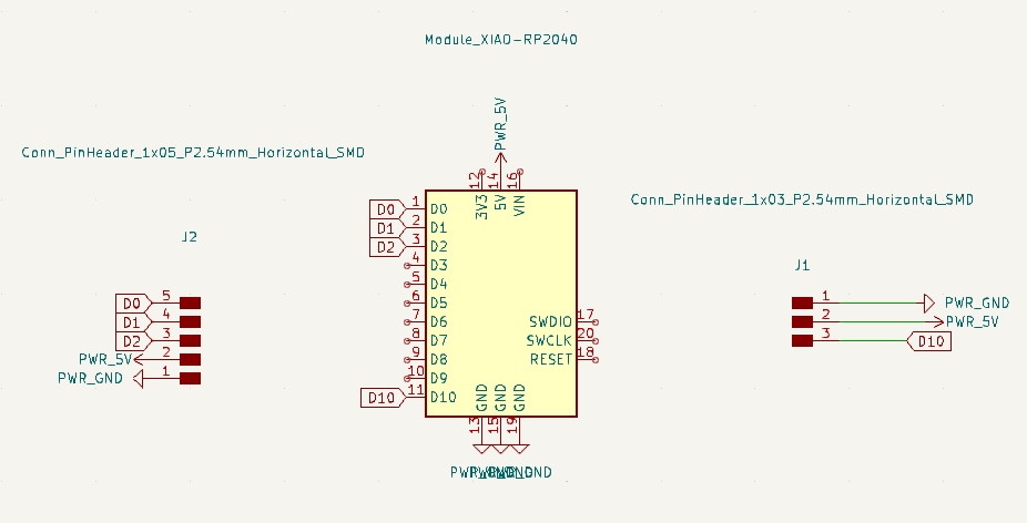
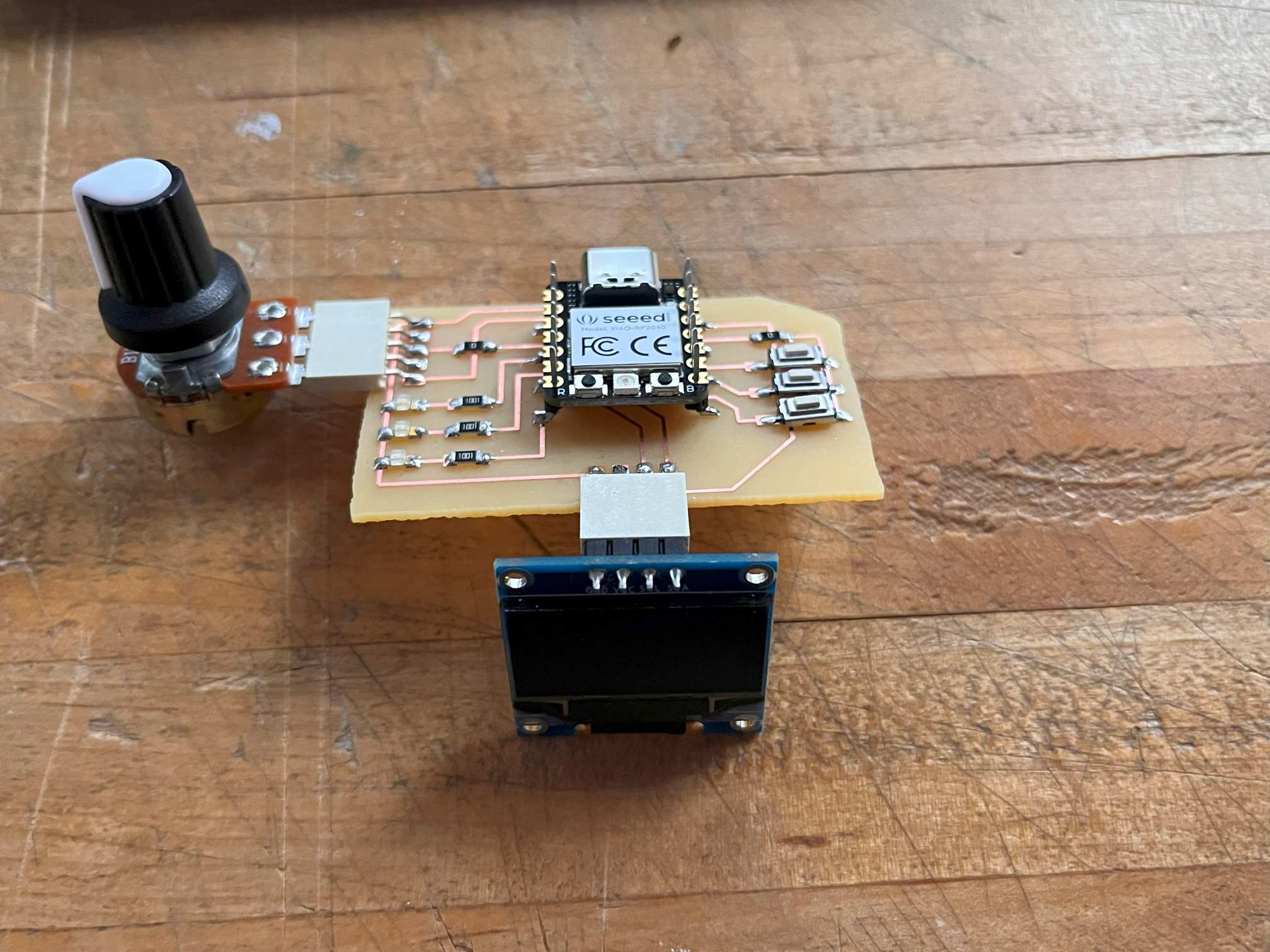
The wiring got a bit messy because I wanted to fit them all on one side of the xiao to save room for the motors for next week. I’ve seen in prior years people do a lot of sub-boards with the attiny45s and such so I am wondering if I should give that a try. I’ve considered switching to the raspberry pico w because it probably has enough room for whatever I will throw at it.
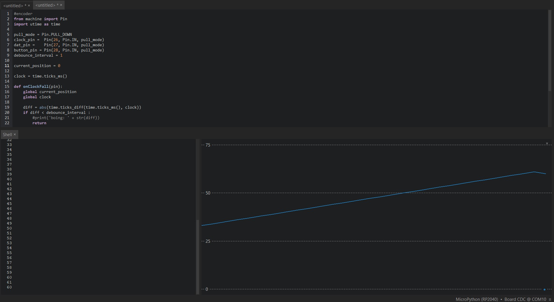
I wanted to code an interactive reader of the rotary encoder knobs to test their fidelity and see if there are any changes I need to make going forward. I also have been having some issues with thonny and micropython and there are so many resources for arduino out there so if this week fails I might switch. Initially I tried to use the Rotary libarary that's been written for micropython and even specified for the rp2, however I wasnt able to get my rotatry encoder to talk to my micropython after hours of debugging and suspecting it would work. I found some code that acted as a base to get readings from my encoder.
        from machine import Pin
import utime as time

pull_mode = Pin.PULL_DOWN
clock_pin = Pin(26, Pin.IN, pull_mode)
dat_pin = Pin(27, Pin.IN, pull_mode)
button_pin = Pin(28, Pin.IN, pull_mode)
debounce_interval = 1

current_position = 0
clock = time.ticks_ms()

def on_clock_fall(pin):
    global current_position
    global clock

    diff = abs(time.ticks_diff(time.ticks_ms(), clock))
    if dat_pin():
        current_position += 1
        clock = time.ticks_ms()
        print(str(current_position))
    else:
        current_position -= 1
        clock = time.ticks_ms()
        print(str(current_position))

clock_pin.irq(on_clock_fall, Pin.IRQ_FALLING)
Between the amount of time trying to go through all of the opions of input devices and tryign and failing at many of them, im glad that I settled on this one. I wasnt able to get to the servo to run it but I will have to eventually to work as the z motion in my final project. I got one to work a couple of weeks back so I am not worried about it.